How To tune up the PWM frequency

MrKang

100 W
Joined
Apr 30, 2009
Messages
297
Location
The Netherlands
Hi i'm new here and i read various threads about controllers and modifications.
I have a YC43 controller from Ebay and its similar as the YK42-3 controller.
Now i read that someone modified thePWM frequency from 2.6KHz to 8 or 15 Khz which produces a bit less noise out of the controller and gives it a better power efficiency. Does anybody can tell me which R/.C i have to change on the LM339 to do this? :?:
 
Yes, that noise is annoying isn't it.

I'm sure there's a way to do it, but I don't recall anyone posting the details here.
I have a picture of the board, but the traces are not very clear in the picture. It will be one of the caps/resistors around the LM339.

If I had a bit better picture of where the traces run, I could probably figure out which one to change.

My wild guess would be the C13 or C14 in the picture. I think the best way would be to replace the timing capacitor with a smaller one and leave the resistors alone.

It would be good if you had a way to measure the new PWM frequency. You don't want it to go too high. 13khz is good for most motors.

Your board may be different. They tend to change the design frequently. Perhaps if you could get a better picture of the area around the LM339 showing the circuit traces, I might be able to tell you exactly.

Another approach would be if you have an oscilloscope, you could poke around the outputs on the LM339 and figure out which section is doing the oscillator.

The crude approach would be to set up the controller so you can hear the PWM (use a small speaker in place of the motor?) and take a small capacitor and temporarily parallel it to the ones on the board. When you touch the right one, the frequency will drop. You should use something around the same value as the ones in there for testing. (can't read them in the pic).

Once you determine which capacitor is running the oscillator, remove it and replace it with one that is about 1/5 the value.
YK-42-3b close up.jpg
 
Thanks for your reply fetcher.

Probably this week i will get a USB Scope to connect it to my notebook. Then i will make some pictures from the controller with my measurments. I soon will update my results.
 
Is there any reason they chose the low PWM frequency in the first place? If it's as simple as changing a couple components, why wouldn't they go with the higher frequency from the start?
 
Good question...

first here is my original setup with my old controller and 750W Bosch motor.
IMAG0039.jpg


It had 4x 12V 12Ah packs on it which provided me 24V on 24Ah. My first upgrade was to buy 4 new accu packs
cause the old ones were working for 40% of lifetime. ( i bought the e-scooter 2nd hand for just a scratch)

After 1 year driving i stalled it in the garage for the winter and wanted to drive again. When i wanted to charge the batteries
i discovered that they also went dead and thought ..'why don't use LiPo's ?' This because at my work we have 2 RC Helifreaks and they
said the same. So after succesfull experimenting with some LiPo configurations i ended up with a 44.4V 20Ah pack.
IMAG0051.jpg


Now the problem was that my original controller has an autmatic shutdown on high battery level, so the only thing to replace was the controller.

I will modify the controller this weekend and give you the results asap, i try to make a video before and after mods. so you can hear the difference in zooming noise produced bij the controller/motor.
 
I think I had the same controller on a brushed Crystalyte 409. Does that motor sound like my old motor in this video?

[youtube]soXj-fN05BQ[/youtube]
 
Yup! Icecube57, that's exactly the same noise..

Here are 2 video's for comparison.

1st one is the first testrun i did with my old controller and 2 packs of 22.2V Lipo parallel connected.

[youtube]C67flX2M1_k[/youtube]

2nd test is after i modded it with a 36V china controller and 5P 44.4V Lipo pack. You can here the difference in noise!
Now i'm going to modify the china controller to get tat frequency higher so you don't hear that.

[youtube]ZrfxOUCXgTw[/youtube]
 
The harmonics on that motor is bad at 22vv. It should go away with high speed like yours did with the 44v setup. I can deal with the noise on start up but yours does it all the way through the rpm curve on 22v. Mines did it even at 60v. Its definetly the controller PWM. Rc motors often have a tune that plays through the motor when the controller starts. Useless but i can help you much more than that but i can suggest that brush controllers are cheap. Buy another.I modded one the size of a wallet with 4310 fets and 100v caps. That thing was crazy fast at 72v. But i dont recommend doing that. Cheack fleabay or tnc scooters is a good place to get stuff cheap... but ur not in america either... crap .
 
First i'm gonna try to modify the china controller to a higher PWM frequency...if the noise has minimized than it's okay...if i still have that irritating noise than i will try another controller maybe from another brand. any sugestions for a 36V/48V 800W controller ?
 
I'm not sure what they were thinking when they designed it with such a low PWM frequency. Probably a EE student who thought switching losses would be reduced by using a lower frequency (true, but not worth the noise).

I'm pretty sure you can just replace one capacitor in there and make the thing much quieter.
 
I'm still waiting for the USB oscilloscope...i hope it arrives soon so then i can measure and experiment with the PWM frequency.
 
This weekend i modified my controller with a higher PWM frequency.

As you can see in the pictures, the controller use a TL494 with an oscillator of 340 Hz. that's why it sounded so hard and noisy.
IMG_3636.jpg

IMG_3638.jpg

PWMfrequency1.jpg


I looked up the specs of the TL494 to figure out the pins of the oscillator. It is generated on pin 5 and 6 with a R/C combination
On the original pcb the components are R25 (56K) and R24(2.2ohms) in serie with C11 (100nF)

I don't know exactly why they use a resistor in series with C11...cause in the specs they only have a R and a C....so...
I first changed the C into 10nF which generated a freq. of 2.48 Khz. I still found that frequency to irritating.

PWMfrequency210n.jpg


Then i changed the R into a smaller value of 25K and that changed it into 4.69 Khz. This i could live with. Still a noise but acceptable.
It's nice to have some noise while driving..
PWMfrequency310nand55kparralel.jpg


You can see here the video of the original 340Hz version with my USB oscilloscope attached on my notebook. On the green line you can see the output to the motor. and the yellow signal is the PWM oscillator.
[youtube]CquH0eh5sIA[/youtube]
 
Nice work!

Most controllers run around 10khz-20khz. The optimum frequency depends on several factors, including the motor construction. At lower frequencies, there are less switching losses and perhaps a bit less core loss due to hysteresis, but the sound is an issue.

5khz should be pretty good as far as efficiency. The sound goes away when you reach full throttle anyway.
 
next weekend i'm gonna change the resistor into a variable one of 50K with in series a 1K to prevend the oscillator from going nuts.
Then i can experiment in PWM frequencies which one is the nicest to drive with.

I also install a RF transmitter to switch on my scooter and a circuit with will activate some recording modules that will play a sample i made with the computer...like if you turn on the scooter you will hear.. " programm complete...enter when ready..." (from start trek)
Also a sample when i trigger my turbo boost button. When it's al setup i will make a new video.
 
My last modification didn't work well... i replaced the resistor of the oscillator with an variable resistor which probably has destroyed my FET's

My first test went well...i just easy turn the throttle and the first thing i noticed was that i didn't hear a zooming noise anymore...it went super smooth and quiet. When i trimmed the variable resistor i heared a variable frequency through the motor...so..all working well ! ..I thought...

Then i put all things in place and went for a test ride...suddenly after 10 sec...i heard a "POOFF"...and my motor shocked forward for a moment...then i heard another "POOF!" and then i smelled it.... a nice mixture of burned carbon and greas... i rapidly disconnected the batteries and gave it a rest.
I just opened the controller and see that there are 2 FET's totaly blown away...Now i can't find the type of FET's what is used in this controller.
I see.. T430 and below that BN7UAP...google didn't find anything... maybe you guys know what i can use to replace this FET..THYRISTOR...

I allready ordered a new controller..now i ordered a 48V 1000W...but i think that these controllers are all the same inside....
 
Hard to say what happened, but if the frequency goes too high, the switching losses may be enough to overheat the FETs, depending on how good the gate drive is. If the gate drive is weak, the FET could be spending a lot of time in the linear region causing massive heating.

The scope traces you posted looked OK, but I would suggest checking the gate signals before attaching a motor. You want the gate signals to have a fast rise/fall time and look very 'square'.

You don't need to use the same FETs as the originals. You could get some IRFB4110s from Methods and use those. There are a wide variety of other choices depending on your voltage requirements and what's available. You would need to replace all the originals, whether they were blown or not. Also check your diodes to make sure none of them are shorted.
 
Thanks Fetcher for your quick reply, i see that i can order these FET's in Germany on Ebay...i looked at several electronic stores here in holland but they didn't came up with these type of FET's. The downsite is..i have to order for 35 euro's on FET's while i just ordered a new controller which allready is shipped out of the USA which only costed me 44 euro's in total...

So i think i wait for that to arrive and then have another try..and i think i'm gonna change the actual resistor with a variable one on the PCB instead of extend it with 2 wires to the alluminium box itself...maybe it had some interference on the wires which causes some distorded pulses..and i will check first after the modification the output on my scope before closing it and testing it on the road..

I'll keep you posted on the new results!
 
Yes, it's funny how you can get a whole controller from china for less than what some of the parts cost.

I am suspicious that the gate driver used may not be adequate to support a higher frequency. Use your scope on the FET gates. This will tell the story.
 
controler just arrived this day on my work. I quickly opened it up to discover whats inside the box.
And the only things that are different were the FET's. all the other components are identical.

(when i'm home i'll upload an image) SOON TO BE PLACED HERE

The Fet's are now replaced by 3 pieces each side with each a skotchy diode (or something..dunno the exact name now)
The FET's are from NEC with type 2SK3435, i downloaded the specs and see that the maximum current is 80A.

More test will come asap.
 
sweet project, i not onl have a charly scooter to mod out but also the same elctric screwdriver :)

i will keep on using the stock SLA´s and keep the e-box onboard as i intend to run a second circuit for charging ( thanks for the t-connector link in the other thread) of the onboard charger which is built-in the same box;

as for the drive controller i was thinking of the 48v/ 800w controller of e-crazyman / HuaQuing north road ( http://cgi.ebay.com/48V-800W-brushed-speed-controller-e-bike-scooter_W0QQitemZ260362843595QQcmdZViewItemQQptZLH_DefaultDomain_0?hash=item3c9ed5b5cb ), he doesn´t tell about the throttle controller method or other details in the item description - does someone have experience on those and if i can marry it up with my existing 5k ohm throttle ?
 
dragonfire said:
as for the drive controller i was thinking of the 48v/ 800w controller of e-crazyman / HuaQuing north road ( http://cgi.ebay.com/48V-800W-brushed-speed-controller-e-bike-scooter_W0QQitemZ260362843595QQcmdZViewItemQQptZLH_DefaultDomain_0?hash=item3c9ed5b5cb ), he doesn´t tell about the throttle controller method or other details in the item description - does someone have experience on those and if i can marry it up with my existing 5k ohm throttle ?

you also have to buy a throttle ..the one on the charly doesn't work for this type of controllers.
 
I know this is already an older topic but i have the same noise problem with my controller and have done experimenting with it which might benefit others as well. And via google you will land in this topic sooner or later when finding a solution to the noise problem :D

So did i, and at first i thought i found the answer in this topic by just replacing a resistor and capacitor. Until i saw that my controller was a bit different. I have the YK43C and that one doesn't have the LM339N.
Until now i still don't know which chip is in the YK43C because they removed the numbers on the chip. But what i know is:
- that it has 18 pins
- has an 4 MHZ crystal
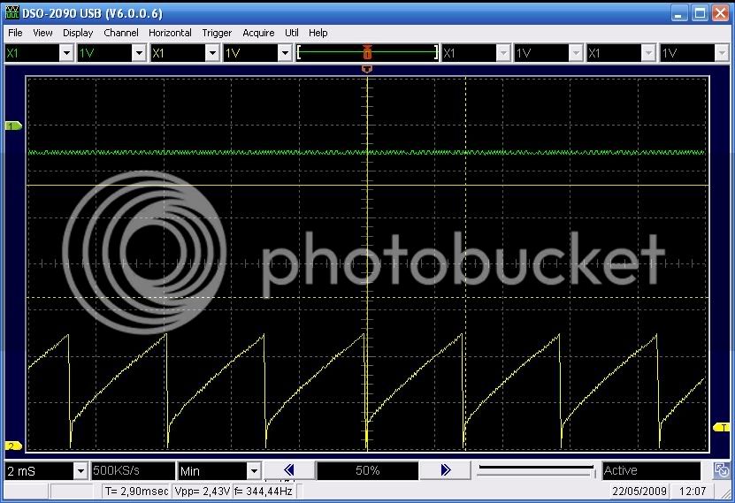
- PWM freq. is 100HZ
- PWM output is pin 9
- PWM signal is approx. 5 Volt
- Transistors are used with the 5 V PWM signal to drive the Mosfet Gates at 10Volt
- No Mosfet driver is used

Because i had no idea what chip was used i wasn't able to change the 100HZ PWM frequency to a higher freq. to reduce the noise.
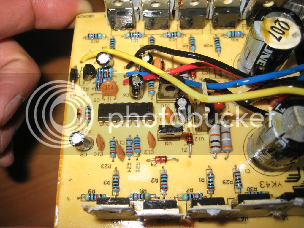
What i knew was that the PWM output was on pin 9 and that this one was driving the transistors via a resistor. So there i came to the idea of disconnecting the onboard PWM signal from the unknown chip and replace it with my own signal. I took a two wire cable and connected one wires to the resistor (PWM) and the other one to ground.

What i did was de-soldering the resistor and connect a PWM signal which i took from an Arduino MEGA. (White wire in the picture)

PWM_on_resistor.jpg


With some heat-shrink tubing and hot glue i fixed it to the board.
PWM_Glued.jpg


The Ground connection (blue wire) was easy. Beside the original black GND wire there are two holes in the board which can be used to make a ground connection.

GND_Connection.jpg


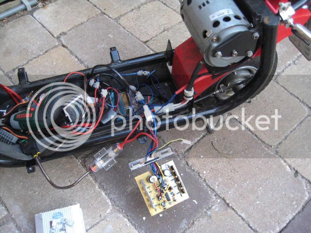
Route the cable outside the housing through the rubber cable entry and reassemble everything.
The next thing to do is to add a pull-down resistor to make sure the Mosfet is driven to a low state if there is no signal present. The easiest way is to connect a resistor between both wires. I used a 1.5K resistor but i think everything between 1K and 10K will do the job.

Pulldown.jpg


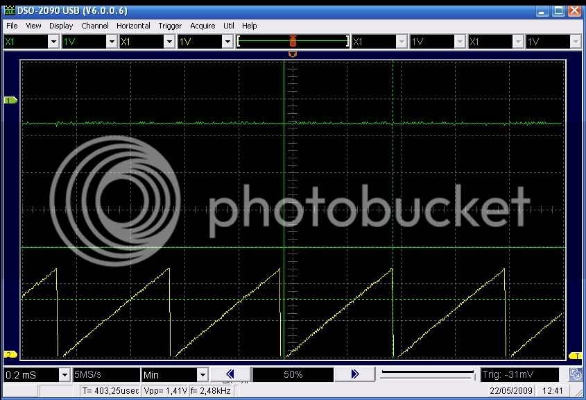
The first test i did was with a 500Hz PWM frequency. This worked but still gave a lot of noise.
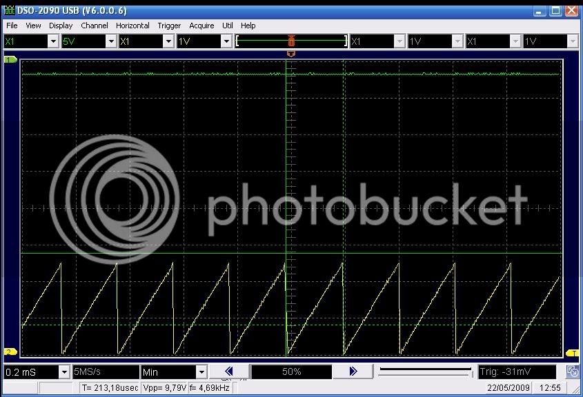
Then i changed the Arduino's frequency to 4KHz. This reduced the noise significantly. There was still a noise but it didn't sounded like a fighter jet taking off anymore. It was an acceptable noise now.

I also tried with a frequency of 7KHZ but this is to much. The controller gets hiccups with that frequency so i took it back to 4KHz. I have only driven it for a short period yet. This week i will get my Arduino wired up in a more definite and reliable way so i can make a longer trip.
I will post my findings here.
 
Tried it out this week and the noise isn't completely gone but is way better than it was.

Only problem i am having is that i am not using the controller on a stand-up E-scooter but on a ebike. And the motor originally is a 24V motor which gets a bit hot now because i ran it at 48Volts.

Will connect 24V to my motor and run some more tests but for now it looks very promising.
 
I AM NOT TRYING TO THREAD JACK but this seemed to be the conversation to be a part of. I had saved this link while looking for a cure to my loud PWM noise.

I am newbie in this site but have already worked on many projects including my current one that I need some help with.

I have a Currie eZip1000. It was a 36volt 1000watt scooter that I got for free so naturally it now has 6 batteries for 72volts and I did a few mods like bigger rear tire, etc. My issue is that I have installed one of these YC43 controllers and it actually seemed to handle the voltage great. It never got really hot that I noticed, the motor gets hotter actually. BUT now it died/freaked out the other day. I was driving it with the batteries low and it suddenly went full throttle all the time now. If the throttle is disconnected or even a new throttle is connected it is wide open the second the power is applied. It seems I blew a input circuit, obviously the drivers can still drive power to the motor but I took it apart and cannot see anything wrong. I found this link before because I also had the noise issue I was planning on working on but now it seems I have to fix it first. Sorry for being long winded, I just wanted people to know what my setup was before asking questions.

I see that you guys seem to have deep knowledge of this controller. Hopefully one of you knows which part of the circuit controllers throttle input. I would just order another one but fear I will burn it up soon anyway. I want to know how to fix this one and mod it to be able to not blow again. Maybe the 72 volts was too much? I can see how that would effect the 0-5v input but obviously something went wrong. Any ideas?
 
You most likely blew one or more of the main FETs and now it's shorted.

If you disconnect the controller, use a meter to measure resistance between the battery neg. wire and the motor neg. wire. If it's good, it will measure like a diode (reverse the meter probes). If it's shorted, well, it will measure like a piece of wire.

You can replace the FETs. If you do, I suggest using better (higher rated) ones.
 
Back
Top