TSDZ2 EBike wireless standard (like Specialized Turbo Levo) - OpenSource

casainho said:
rananna said:
Yes, but we configure the nrc as gpio so they work as button input.
I measure no increased power consumption on this pin compared to other gpios.
I also see nothing on the nordic forum suggesting the use of these pins are an issue with power consumption.

Have you found a power issue with this pin?
Well, after 24h, seems the battery is dead again. So, I really need to monitor the current by myself. Why you are not using yet the wireless remote?
Unfortunately I have had some health issues that prevent me from riding.
All I can do is bench testing for now.
Is the battery draining when the nrf52840 is out of the enclosure?
I would request that you please test on the bench so we can at least eliminate any enclosure related issues.
 
rananna said:
Unfortunately I have had some health issues that prevent me from riding.
All I can do is bench testing for now.
Is the battery draining when the nrf52840 is out of the enclosure?
I would request that you please test on the bench so we can at least eliminate any enclosure related issues.
I wish you a quick recovery.

About the issue, I used a 15 ohms resistor in series with 2 AAA NiMh batteries (2.3 volts), to power the wireless remote. I did measure with oscilloscope the voltage across the resistor and here is the result:

1. Wireless remote without any power supply - 9.85mV for 0 amps current:


2. Wireless remote working, no LED on, TSDZ2 wireless board off:


3. Wireless remote working, no LED on, TSDZ2 wireless board on with TSDZ2 motor off:


On 3. there are peaks of 166 - 10mv = 156mv, which means peaks of 10mA.
 
And this is with brake pin active (connected as original schematic):


So, PWM every 1ms and very small duty-cycle to turn on the red LED of brake signal. The large impulse at middle of the image, happens every 250ms and is the ANT+ LEV reception and processing.

In my calculations, if TSDZ2 wireless board ANT+ LEV is not transmitting, the wireless remote battery will work at best for about 2.5 years but if ANT+ LEV is always transmitting, the remote battery at best will only work for 8 months.

I did put the NRF52 board inside the wireless remote and measured again and I did not see nothing about the possible issue. The current values all seems the same and ok.

Maybe the next step should be to build a wireless remote but with 1 hole to put outside the resistor to measure the current and also wires to measure the battery voltage, so I can monitor it.
 
Finally I was able to find the issue!!

Easy to replicate: with the TSDZ2 wireless board is off, click on any button of the wireless remote to make it work. Then, click 1 or more times on the down button and then long press on the down button (sometimes you need more than 1 long press) -- then the wireless remote will pull continuous 6.5mA and stop responding to the buttons press, so keeping draining the battery!! The CR2032 battery has about 180mAh, meaning it will drain in about 27 hours!! -- this is for sure what was happening to me all the time.

The same happens if TSDZ2 wireless board is on and then I see the same 6.5mA + the impulse of current used by receiving the ANT from the wireless remote (1 pulse every 250ms).

Now, how to solve this?? what is the source of this issue?? Note that seems to happen only with DOWN or ON/OFF buttons, not with the other buttons. If I click the reset button, the system resets and go back to normal as usual.
 
Meanwhile I found:
- the used current is the same as if the microprocessor is running at 100%
- if a debug and stop the system, I can not see the place in code it is running and if I click continue, it will continue and using the same amount of current (it is like if is running on an infinite loop and without the softdevice running, otherwise there would be an exception after I click continue)
- if I disable the power on/off pin on the initialization, then the long press on this will not trigger the issue
- if this issue is triggered while the red LED is on, then it will keep always on at max brightness (like if the PWM stops at a fixed position)
 
casainho said:
Meanwhile I found:
- the used current is the same as if the microprocessor is running at 100%
- if a debug and stop the system, I can not see the place in code it is running and if I click continue, it will continue and using the same amount of current (it is like if is running on an infinite loop and without the softdevice running, otherwise there would be an exception after I click continue)
- if I disable the power on/off pin on the initialization, then the long press on this will not trigger the issue
- if this issue is triggered while the red LED is on, then it will keep always on at max brightness (like if the PWM stops at a fixed position)

my guess is nrf_delay_ms being called somewhere in the remote code - but haven't looked at the code. I think as well as effectively causing 100% cpu - they also block interrupts which would explain the pwm hang... but just a guess!

edit: I should check before pointing fingers - I can't find any nrf_delay being used in the remote code - so can't be that - sorry rananna :)
 
beemac said:
casainho said:
Meanwhile I found:
- the used current is the same as if the microprocessor is running at 100%
- if a debug and stop the system, I can not see the place in code it is running and if I click continue, it will continue and using the same amount of current (it is like if is running on an infinite loop and without the softdevice running, otherwise there would be an exception after I click continue)
- if I disable the power on/off pin on the initialization, then the long press on this will not trigger the issue
- if this issue is triggered while the red LED is on, then it will keep always on at max brightness (like if the PWM stops at a fixed position)

my guess is nrf_delay_ms being called somewhere in the remote code - but haven't looked at the code. I think as well as effectively causing 100% cpu - they also block interrupts which would explain the pwm hang... but just a guess!

edit: I should check before pointing fingers - I can't find any nrf_delay being used in the remote code - so can't be that - sorry rananna :)
No problem!
All ideas all welcome.
 
Seems the problem is here: void send_page16(ant_lev_profile_t *p_profile)

do
{
err_code = sd_ant_acknowledge_message_tx(p_profile->channel_number, sizeof(p_message_payload), p_message_payload);
// } while (err_code == NRF_ANT_ERROR_TRANSFER_IN_PROGRESS);
} while (err_code);

If I comment the send_page16(), there is no more issue. I had luck because the debugger once did stop on the send_page16().
 
casainho said:
Seems the problem is here: void send_page16(ant_lev_profile_t *p_profile)

do
{
err_code = sd_ant_acknowledge_message_tx(p_profile->channel_number, sizeof(p_message_payload), p_message_payload);
// } while (err_code == NRF_ANT_ERROR_TRANSFER_IN_PROGRESS);
} while (err_code);

If I comment the send_page16(), there is no more issue. I had luck because the debugger once did stop on the send_page16().
Interesting..... I added this code to ensure that the send page 16 command gets an acknowledgement form the motor for the page16 command before proceeding. obviously when the acknowledgement fails it goes into a continuous loop and burns up power!!
Good catch and sloppy coding on my part.
It would be better to simply press the button again if the message does not get received.
I will eliminate the do loop and give you a PR
 
Some news:

1. I did a nice update on the project page, like main page focus on TSDZ2 EBike wireless controller, mobile app and fully wireless remote and wired remote. On this main page there are pictures of this 3 parts. I also added screenshots on the mobile app page and wrote some notes.

2. @rananna documented a different build and 3D design for the wireless remote: https://opensourceebike.github.io/remote/alt/build_remote.html

 
Great work with this project. I'm currently wanting to cut down on wires on my bike so this project sounds interesting.

Would this project work without a remote (ie power on the battery and the motor would turn on at default levels set previously with the app)?

Thanks
 
stek692003 said:
Great work with this project. I'm currently wanting to cut down on wires on my bike so this project sounds interesting.

Would this project work without a remote (ie power on the battery and the motor would turn on at default levels set previously with the app)?

Thanks

Not as things stand - you still need something to turn on the motor other than the battery switch - but you don't need a remote - you can use the android app to switch on - then turn the app off if you like and leave phone at home although that's not recommended as you then wouldn't be able to turn the bike on again if the battery got disconnected.

Essential components are the wireless controller and the android app - the buttons (wired or wireless) are effectively optional...

edit: It's not a bad feature though - to be able to configure the controller to turn on the motor as soon as things are ready... definitely something i'd use - I'll add it to the list of things I'm looking at for the next release...
 
beemac said:
stek692003 said:
Great work with this project. I'm currently wanting to cut down on wires on my bike so this project sounds interesting.

Would this project work without a remote (ie power on the battery and the motor would turn on at default levels set previously with the app)?

Thanks

Not as things stand - you still need something to turn on the motor other than the battery switch - but you don't need a remote - you can use the android app to switch on - then turn the app off if you like and leave phone at home although that's not recommended as you then wouldn't be able to turn the bike on again if the battery got disconnected.

Essential components are the wireless controller and the android app - the buttons (wired or wireless) are effectively optional...

edit: It's not a bad feature though - to be able to configure the controller to turn on the motor as soon as things are ready... definitely something i'd use - I'll add it to the list of things I'm looking at for the next release...

This sounds exactly like the direction I am looking to do on a simple/minimalist experimental build. Either use the phone app to turn the system on in "headless" mode with pre defined parameters or potentially just power on a pre-configured system without the phone at all.
 
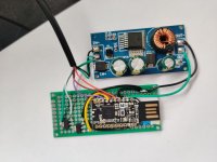
I received the EBike buck dd7818ta 80V and is bigger than what I expected. Well, at least I hope it will not burn as the previous DC-DC I was using :)

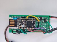
I will need to build again my TSDZ2 wireless, so I hope to get the opportunity to take some good photos for the documentation. And looking at the area of this DC-DC, there will be no need to cut the USB part of the NRF52 board:

 
Finally I am building my TSDZ2 EBike wireless controller!!

And there are only 2 wires to solder on the board + that 2 mosfets. The other wires missing are the ones to the TSDZ2 motor controller extension cable:


Hello Casainho, First of all, well done for all the great work you have done to date! I am also building the board but I have encountered some issues. I wil try to explain. I have exactly the same buck but my nRF52840 is a Makerdiary as in your original pictures in https://opensourceebike.github.io/ not a Nordic nRF52840. The pictures and the schematics are different when I look at them and this for me is a bit confusing see pictures SchematicConfiguration and PhotoConfiguration. I have managed to flash my nRF52840 and also flashed the motor with the latest 1.1.1 Hex file. My nRF52840 connects to the app but the motor does not react to any changes I make. The App seems to not receive any data, I think that I may have soldered the cables wrong to the nRF52840 and therefore not sending the information to the app. The bootloader I have installed is 0.7 as 0.9 would not work. The APK I am using is 0.3.1. attaching all the photos I have. Could you help me confirm how I need to solder the cables so that it works? I also can't figure out how to enter the DFU mode once I have flashed the bootloader (Reset button does not seem to work on Makerdiary). I am also interested in developing the wired remote, I have it all ready I just need to know where to solder the cables. I can help with creating documentation in spanish and german if you wish.
 

Attachments

  • SchematicConfiguration.jpg
    SchematicConfiguration.jpg
    251.1 KB · Views: 732
  • PhotoCofiguration.jpg
    PhotoCofiguration.jpg
    227.2 KB · Views: 732
pepelapera said:
Hello Casainho, First of all, well done for all the great work you have done to date! I am also building the board but I have encountered some issues. I wil try to explain. I have exactly the same buck but my nRF52840 is a Makerdiary as in your original pictures in https://opensourceebike.github.io/ not a Nordic nRF52840. The pictures and the schematics are different when I look at them and this for me is a bit confusing see pictures SchematicConfiguration and PhotoConfiguration. I have managed to flash my nRF52840 and also flashed the motor with the latest 1.1.1 Hex file. My nRF52840 connects to the app but the motor does not react to any changes I make. The App seems to not receive any data, I think that I may have soldered the cables wrong to the nRF52840 and therefore not sending the information to the app. The bootloader I have installed is 0.7 as 0.9 would not work. The APK I am using is 0.3.1. attaching all the photos I have. Could you help me confirm how I need to solder the cables so that it works? I also can't figure out how to enter the DFU mode once I have flashed the bootloader (Reset button does not seem to work on Makerdiary). I am also interested in developing the wired remote, I have it all ready I just need to know where to solder the cables. I can help with creating documentation in spanish and german if you wish.
So, I really suggest you to move to the NRF52 board we are using.

I bought a mosfet from Aliexpress and it was not working so the TSDZ2 motor never turned on, so, I had to use that small one I had that works - can this be your issue?? check with a multimeter if the TSDZ2 motor controller have the needed battery voltage after the mosfets turn that on (yellow wire on this picture):
 
pepelapera said:
Hello Casainho, First of all, well done for all the great work you have done to date! I am also building the board but I have encountered some issues. I wil try to explain. I have exactly the same buck but my nRF52840 is a Makerdiary as in your original pictures in https://opensourceebike.github.io/ not a Nordic nRF52840. The pictures and the schematics are different when I look at them and this for me is a bit confusing see pictures SchematicConfiguration and PhotoConfiguration. I have managed to flash my nRF52840 and also flashed the motor with the latest 1.1.1 Hex file. My nRF52840 connects to the app but the motor does not react to any changes I make. The App seems to not receive any data, I think that I may have soldered the cables wrong to the nRF52840 and therefore not sending the information to the app. The bootloader I have installed is 0.7 as 0.9 would not work. The APK I am using is 0.3.1. attaching all the photos I have. Could you help me confirm how I need to solder the cables so that it works? I also can't figure out how to enter the DFU mode once I have flashed the bootloader (Reset button does not seem to work on Makerdiary). I am also interested in developing the wired remote, I have it all ready I just need to know where to solder the cables. I can help with creating documentation in spanish and german if you wish.

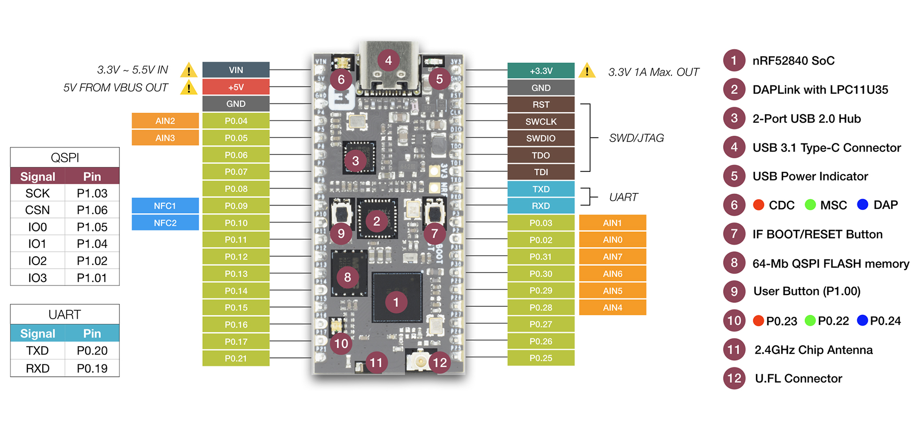
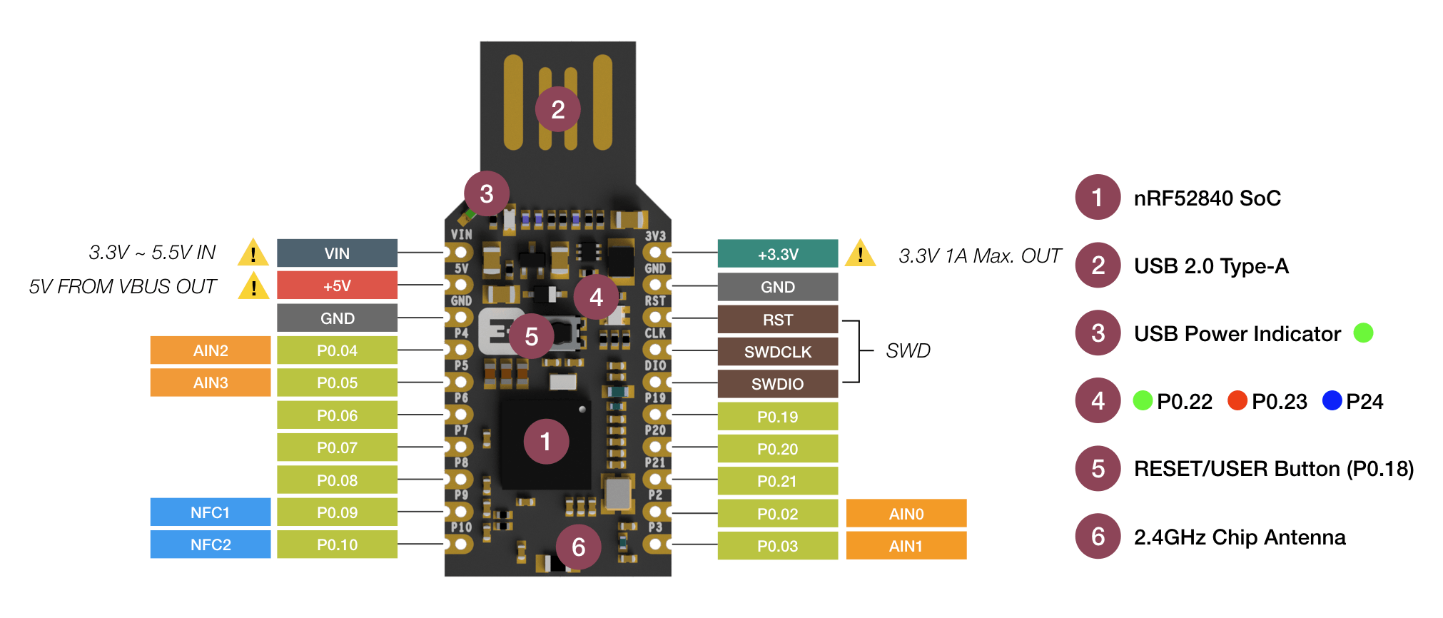
You need to look at the pin numbering on the schematic and map that to the pin numbers on the makerdiary board... but the problem is that it looks like the boards don't expose the same pins from the chip... most importantly p0.22/0.24 are missing which are the tx/rx lines to the motor...

nrf52840-mdk-pinout.jpg


TSDZ2_wireless-schematic.png


For the sake of 10 euros - it's worth getting the blue dongle - otherwise you'll need to compile your own firmware with different pin definitions - and maybe other changes...
 
beemac said:
pepelapera said:
Hello Casainho, First of all, well done for all the great work you have done to date! I am also building the board but I have encountered some issues. I wil try to explain. I have exactly the same buck but my nRF52840 is a Makerdiary as in your original pictures in https://opensourceebike.github.io/ not a Nordic nRF52840. The pictures and the schematics are different when I look at them and this for me is a bit confusing see pictures SchematicConfiguration and PhotoConfiguration. I have managed to flash my nRF52840 and also flashed the motor with the latest 1.1.1 Hex file. My nRF52840 connects to the app but the motor does not react to any changes I make. The App seems to not receive any data, I think that I may have soldered the cables wrong to the nRF52840 and therefore not sending the information to the app. The bootloader I have installed is 0.7 as 0.9 would not work. The APK I am using is 0.3.1. attaching all the photos I have. Could you help me confirm how I need to solder the cables so that it works? I also can't figure out how to enter the DFU mode once I have flashed the bootloader (Reset button does not seem to work on Makerdiary). I am also interested in developing the wired remote, I have it all ready I just need to know where to solder the cables. I can help with creating documentation in spanish and german if you wish.

You need to look at the pin numbering on the schematic and map that to the pin numbers on the makerdiary board... but the problem is that it looks like the boards don't expose the same pins from the chip... most importantly p0.22/0.24 are missing which are the tx/rx lines to the motor...

nrf52840-mdk-pinout.jpg


TSDZ2_wireless-schematic.png


For the sake of 10 euros - it's worth getting the blue dongle - otherwise you'll need to compile your own firmware with different pin definitions - and maybe other changes...

Ah there they are - p0.22/p0.24 are assigned to the green and blue LEDs! :)

edit - just realised I wasn't looking at the makerdiary dongle - but it's the same, the tx/rx pins are assigned to the led.

nrf52840-mdk-usb-dongle-pinout.png
 
Yep! clear now! Similar is not the same! Lesson learnt, ordered 2 Nordic nRF52840. Posting and Packaging more expensive than the dongles... ;)
 
sidmodi said:
Has anyone built the controller using the Traco power TEC-2-4811WI voltage converter?


not that specific traco - but I've used the https://www.tracopower.com/int/model/tsr-1-4850wi

but if you want a more compact solution - I've also used two of these and they seem to work well and be reliable.

https://uk.rs-online.com/web/p/switching-regulators/1883365
 
Oh okay. I ordered the TEC-2-4811WI for my build since it was listed on the Wiki. So I'll build the circuit and not connect the nRF and measure the voltage with a DMM first. Based on the specs, the TEC-2-4811WI seems like it will work but I would hate to damage the nRF. If anyone has used it before, please let me know. Else I'll report back once I have some results.
 
sidmodi said:
Oh okay. I ordered the TEC-2-4811WI for my build since it was listed on the Wiki. So I'll build the circuit and not connect the nRF and measure the voltage with a DMM first. Based on the specs, the TEC-2-4811WI seems like it will work but I would hate to damage the nRF. If anyone has used it before, please let me know. Else I'll report back once I have some results.

ok yea I've yet to fry an nRF and my dev one gets power cycled a lot - and powered from one or both sides - either by the st-link or by the battery/bench psu so they seem to be fairly robust.
 
Back
Top