how to program a sevcon gen4

evc_motorcycle said:
Hi everythingisawave, I believe that the only things that changed between my weird (kind-of) circular graph and the one I recently posted were the firmware on my controller and the order of my sin-cos wires. I had determined the correct color association, but then plugged them into pins 35/21 in the wrong order :roll: . There was also a bad connection between the +5V supply and the ME1302 encoder, so that wire had to be replaced.
After those few things, the instructions here: https://endless-sphere.com/forums/viewtopic.php?t=88647 were what I used. Our dynamometer is currently out-of-commission, so I used the method with setting 0 torque and spinning the motor with a power drill.

OK thanks. Looks like bad power connection would have done it, and also earlier on not enabling the forward switch during calibration, perhaps. Lessons learned..
 
everythingisawave said:
Good idea, a wiki would be great but would take more work.

i would prefer a single topic with multiple "sevcon specialists" having rights to edit the posts in that topic. that would negate the use of a wiki wich is a lot harder to maintain. but using a forum this way does require assistance from the moderators/admins to create a new usergroup and probably a dedicated forum entry for sevcon people to "moderate" themselfs and keep a clean "information only" topic and a "seek help" topic for example. that would remove the burden of work for mods to police more of hte forum.

it would be a bit of work but copying all sevcon information and questions to a single point in this forum would make it a center for people to learn to use these controllers properly because as we all know how much of a PITA sevcons can be to learn and operate.
 
evc_motorcycle said:
I had determined the correct color association, but then plugged them into pins 35/21 in the wrong order :roll: . There was also a bad connection between the +5V supply and the ME1302 encoder, so that wire had to be replaced.

Those things are quite common. Another common problem is that the sin-cos sensor must be placed at the relatively exact distance from the magnet on the rotor. If it is placed too close or far away you can also find problems with reading values.

And finally a great feature of DVT software is that when you sometimes changed a value in pre-op, saved it(Load Values) and then you immediately go to operational, the value is for some unknown reason not uploaded into the controller and so the controller hapilly uses an old value. So you are thinking that your change does not any effect but in reality no change happened at all. :roll:

A good practice to avoid this behavior is to do an "power off/on cycle" after each Load Values button press.
 
j bjork said:
A new sub forum for programming tricky controllers would surely be something, with sevcon on top of the list.
But other controllers as APT or ASI would of course fit there too in that case.

a subsection for every controller brand would be great and would concentrate practical information and clear the rest of the forum with controller issues related to a vechicle type wich is extremely restrictive. sevcon is very popular in the plane section but the scooter section also has sevcon users that never read the plane section.
when discussing controller issues and programming the thing the controller is put into is not actually relevant from a technical perspective so removing controller related questions to a central area would be very useful in cleaning up the forums and would allow moderators to just dump all topics created for controller based questions into their respective home and clearing up the original subsection.

but we would need a moderator/admin to get some input if such a change to the forum is allowed by the powers-at-be, as the forum is certainly capable. i have used this forum software for years when i was admin/moderator on a couple forums. its not hard to create a new subsection....
 
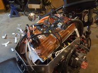
Seems like this thread is about the best place to put this update, new threads wouldn't see the same traffic. After all the tuning, I always had bad EMI contaminating my sin/cos encoder lines and was still using bypass capacitors to dampen the noise. Double shielded cables, and still, no amount of PI tuning could maintain stability perfectly well that I could open up full power. I'd be 90% there, but would always get a bit of a growl at top speed, full throttle - occasionally tripping off too, welding the contactor. A real PITA in Calgary traffic.

This weekend I gift-wrapped the controller with copper tape after thinking about how Zero wrapped their controllers with a shielding blanket, ground to frame via contact with the cold plate. The noise quieted down significantly. I'm blown away at how much noise must be radiating out of the controller body. I feel like tuning and performance-wise, I'm finally done. I haven't seen anyone else talk about this, does nobody else seem to need this level of shielding??

For background, I'm running gen4 size 6, Parker GVM142 motor, Renishaw 5v sin/cos encoder. Top end voltage about 107v.
Cheers
Darsey
 
Hello,
I have a probelm I can not solve...
after some days work I got my ME1114 with the GEN4 running. Problem:
After some seconds spinning, the motor slow down and stop. Only with power recycling I can get him spin again.
(I use the motor in speed mode..)
The Battery voltage is stable....
The only crazy value I notice is: "Voltage limit circle magnitude" goes up to 32212A when the motor is slowing down.

greetings, Michael
 
No errors before the power cycle? That's strange if it doesn't have an error but still requires a power cycle. Overall, there are quite a few limits in the program that would trip the unit off, but I expect to see an error in DVT that tells you which one tripped you off.

From the tuning perspective: overcurrent trips can still come with very little throttle (low power demand in speed mode) if the PI gains are bad, or similarly with poor encoder settings or unshielded encoder wires.
If you take a trace while this happens, how erratic or smooth is your Iq curve? Hit momentary overcurrent in a spike, or tracks Iq target well but simply trips off without any other indication? Maybe the primary motor parameters are significantly off, like Ke value is much too high, or inductance is wrong?

Darsey

Sent from my SM-N770F using Tapatalk

 
Thanks Darsey for you hints,
I used a DCF for the ME1114, so I think the main parameters must be correct.
Until now I use standard encoder settings ond dont trace the motor. Its the first time I use a PMAC motor and I thought, there is a easy solution.
So it seems I have to dig deeper.....

Greetings, Michael
 
OK,
was a stupid error, "Master Battery Curent Limit Parameters (0x2870)" was enabled but with no values ....
 
darseygodwin said:
Seems like this thread is about the best place to put this update, new threads wouldn't see the same traffic. After all the tuning, I always had bad EMI contaminating my sin/cos encoder lines and was still using bypass capacitors to dampen the noise. Double shielded cables, and still, no amount of PI tuning could maintain stability perfectly well that I could open up full power. I'd be 90% there, but would always get a bit of a growl at top speed, full throttle - occasionally tripping off too, welding the contactor. A real PITA in Calgary traffic.

This weekend I gift-wrapped the controller with copper tape after thinking about how Zero wrapped their controllers with a shielding blanket, ground to frame via contact with the cold plate. The noise quieted down significantly. I'm blown away at how much noise must be radiating out of the controller body. I feel like tuning and performance-wise, I'm finally done. I haven't seen anyone else talk about this, does nobody else seem to need this level of shielding??

For background, I'm running gen4 size 6, Parker GVM142 motor, Renishaw 5v sin/cos encoder. Top end voltage about 107v.
Cheers
Darsey
Can you define "growling"?
I ask because when inride my bije , inget this weird kind if shudder that seems to be coming from the driveline somewhere. I have realligned the encoder but to no effect. Since my motor and controller are placed very close together i find your findi gs about EMI to mess up the encoder signal very interesting. I guess it couldnt hurt to try wrappig my controller in copper tape. How did you do this ? Did you cover up the motor terminals with insulating tape first?

Regards,

Sander
 
Hey Sander, I didn't let the copper very near any terminals. Basically kept it below the bosses that the terminals are on, and the terminals themselves had tape (and liquid tape) right up to the contact patch.
Taped up Controller.jpg

Whenever the stator current exceeds its peak current, it makes an arcing sound down at the motor. Do that consistently under load, and, well, at 6kHz it sounds more like a growl than a snapping sound. (that's my take on what's happening anyway). When EMI noise (or possibly bad encoder lag) causes the encoder reading to be inaccurate, the Iq/Id stability gains are fighting to keep the Iq current right - aka oscillating. You can see it when taking a trace in DVT. Well if that target current is near the actual motor limits, then any appreciable instability causes it to jump up over the actual current limits and that's when it happens. Bad enough and it shuts off on an overcurrent limit fault. Also significantly worse at the upper voltage limits of the controller. If you're well below the operating voltage limits, the controller might be able to suppress it a bit better but I'm not very sure about that being a real fact.

So full circle, after wrapping the controller, the amplitude of the instability/oscillations dropped from maybe 60A down to ~20-30A at full crank, top speed. Not perfect but much more managable for me. Here, the encoder wires were heavily shielded, all phases and DC cables are shielded, and any little wire connected to B- is also shielded.

Darsey
 
darseygodwin said:
Hey Sander, I didn't let the copper very near any terminals. Basically kept it below the bosses that the terminals are on, and the terminals themselves had tape (and liquid tape) right up to the contact patch.
Taped up Controller.jpg

Whenever the stator current exceeds its peak current, it makes an arcing sound down at the motor. Do that consistently under load, and, well, at 6kHz it sounds more like a growl than a snapping sound. (that's my take on what's happening anyway). When EMI noise (or possibly bad encoder lag) causes the encoder reading to be inaccurate, the Iq/Id stability gains are fighting to keep the Iq current right - aka oscillating. You can see it when taking a trace in DVT. Well if that target current is near the actual motor limits, then any appreciable instability causes it to jump up over the actual current limits and that's when it happens. Bad enough and it shuts off on an overcurrent limit fault. Also significantly worse at the upper voltage limits of the controller. If you're well below the operating voltage limits, the controller might be able to suppress it a bit better but I'm not very sure about that being a real fact.

So full circle, after wrapping the controller, the amplitude of the instability/oscillations dropped from maybe 60A down to ~20-30A at full crank, top speed. Not perfect but much more managable for me. Here, the encoder wires were heavily shielded, all phases and DC cables are shielded, and any little wire connected to B- is also shielded.

Darsey

thx for the reply. That actually looks pretty cool that taped controller. I Managed to source myself a new battery, so as soon as its in, i will make a trace in DVT to see what exactly is going on.
 
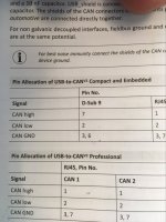
Hello all, I am new to EV's, and am currently trying to bench test a powertrain that has a Motenergy 1117 and a Secvon Gen4 Size 2 Controller. We have the whole system wired, but cannot get the secvon to connect to ixxat. I made a cable with a spare sevcon connector and a female d-sub 9 connector. However the pinouts in the ixxat manual are unclear. It says that CAD GND goes to pins 3,6 (see picture). I made my wire with the CAN GND from the sevcon going to pin 6. Is CAN GND supposed to go to one or the other or both?
190343687_1417900725211617_2881038715321133389_n.jpg
 
@jrory I'd say it seems like your logical next step is to install a jumper. I'm guessing if it didn't work for you then one actually just connects to the shield.

Sent from my SM-N770F using Tapatalk

 
@jrory
there's more unclear than just the pinout :wink:
Normally all IXXAT devices are fine with CAN-L on pin 2 of the Sub-D, CAN-H on pin 7 and GND on pin 3.
On the Sevcon-side you should shorten pins 2 and 24 (alternatively 27) for proper termination.
Unclear is, how you determine that there's no connection?
What software do you use with the IXXAT? If you really use the v2, you need a new, paid version of DVT.
The old "free" versions aren't able to initialise the adapter.
Or dou you just check the connection with canalyser?
Baudrate should be 500kB with sevcon gen 4s.
Give us more information about the setup...
 
I have so far only looked at a file online and read manuals, but I planned to try to find out the motor parameters necessary before it is time to start programming.
But it is unclear to me what motorparameters I need to know, and what can be found while running the motor.

I basically only know pole pairs and kv now..
 
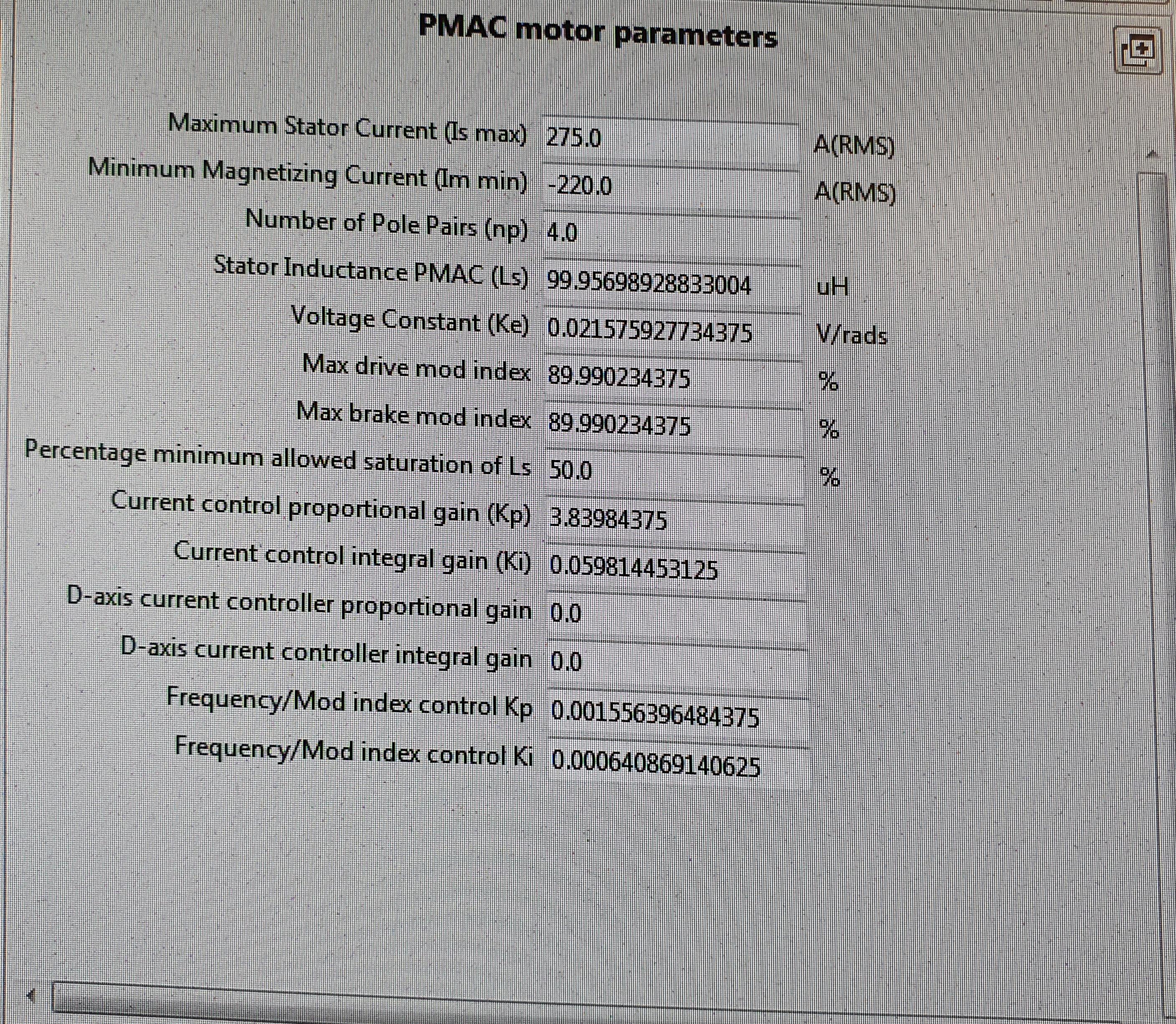
Thanks, menus look like this:

ZRGPb4l.jpg


There is inductance, but it seems to me like an odd number.
I would probably just call it 100 if I would have written it.
Ke looks a bit odd too.

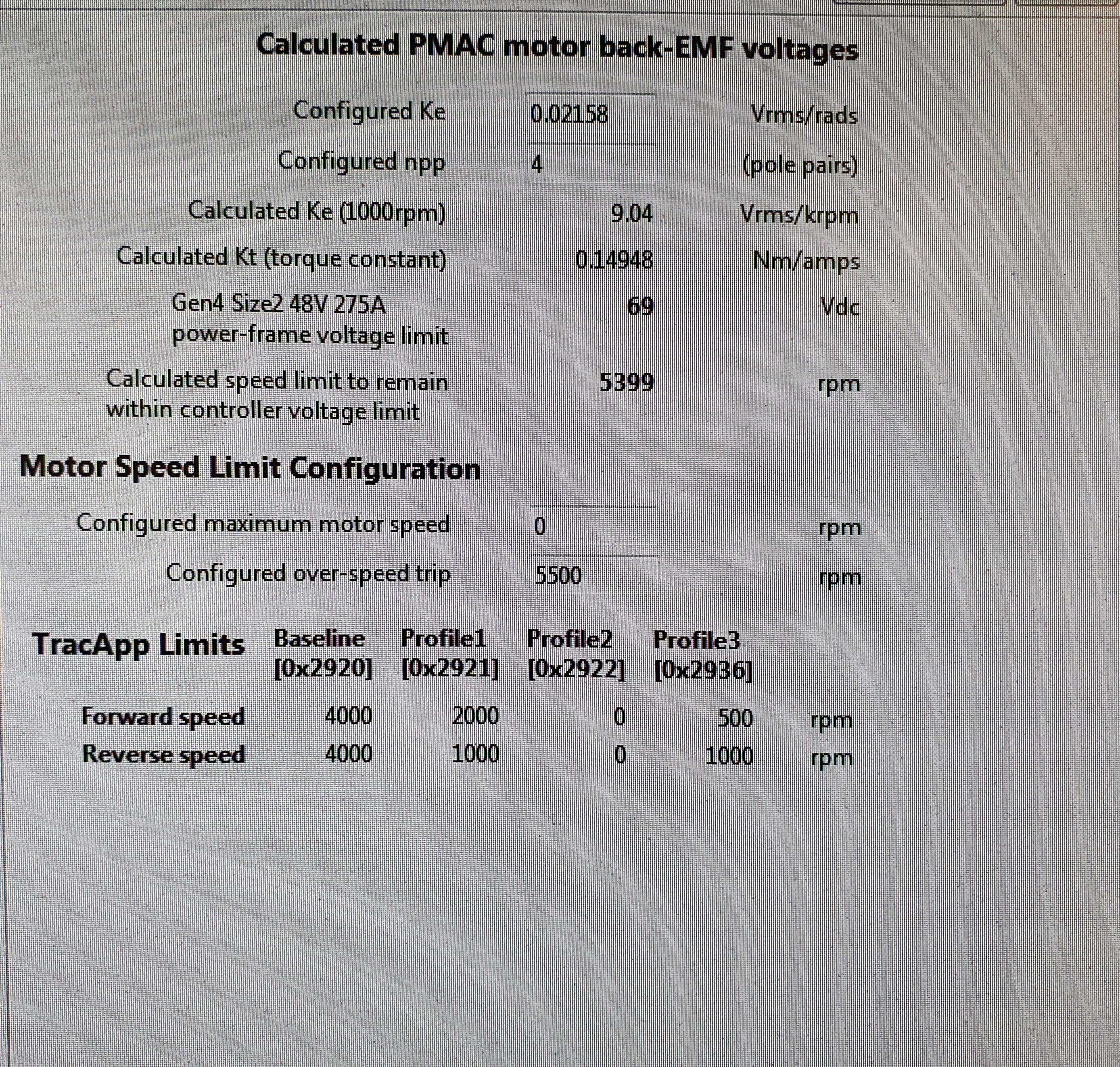
Then there is this:

1LNPyh2.jpg


There is a calculated Ke, and a calculated Kt.

I guess I should have read up better before starting asking questions, but I was mostly after if someone with experience of sevcon could say " you need Ke and inductance, then you are good to go" or something like that.
Then I could ask qs very specific questions. If I only ask for "motor data", the answer will probably not be what I want :wink:
 
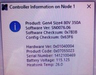
Hello everyone, I need help, I'm converting zero fx 2015 if someone has a dcf file working with a gene4 controller size4 and a zero 75-5 motor, I have dvt i ixxat v2 software, I removed MBB from the circuit, collected the battery out of 28 cells 50a \ h I use a smart bms 300a I will be grateful for any help the controller data in the photo with respect AlexIMG_20210607_155107 (2).jpg :(
 
@aleks68 those aren't failures or error codes. It's the same as any "about" page. Simply tells you what versions of everything you have, pack voltage etc. The checksum is an error check you can use to make sure the program was uploaded to the controller correctly.

Sent from my SM-N770F using Tapatalk

 
I didn't mean codes and failures, I ask you to help start the controller, maybe someone in the future, this information will also come in handy, where I just did not contact nobody could specifically help me to reconfigure the controller, therefore, I want to at least approximately find dcf file to work with my controller and motor, regards
 
Anyone know how to add a new variable to a gen4 controller? In my case, I care mostly about adding an odometer. Can't seem to find an answer on my own.

Sent from my SM-N770F using Tapatalk

 
Good day everyone, I'm Samet. we are the university electric car team in turkey, we have difficulties in reading information from the motor driver while making an electric car. To give details, we are using sevcon gen 4 motor driver and we are trying to get information from sevcon gen 4 with canbus shield, but we can't get any information. Our aim is to reflect information such as motor speed, torque, battery status to the screen with canbus shield using arduino. Can you help us with this problem? How can we extract information from Sevcon gen 4 for arduino?
 
Back
Top