You are using an out of date browser. It may not display this or other websites correctly.
You should upgrade or use an alternative browser.
You should upgrade or use an alternative browser.
40T, neodymium magnets, plasti dip cycle test
- Thread starter goatman
- Start date
goatman
10 MW
Dak77 said:Do you have any idea how long the 10mm magnets hold their "strength" ? I understand that they are supposed to lose very little for like a hundred years normally, but does current passing through them change that ?
i havent seen any loss of strength, i limit my testing to 104f/40c, i think these have a working temperatur of 50 or 80 celsius
ive soldered to them and it lost half its strength
current doesnt pass through the magnet as far as i can tell
if you hear me say, "i had the seam down" it means the current was trying to pass through the conductive adhesive and discharge curve craps out
so i made to sure to mark the seam side up with black felt
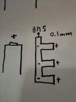
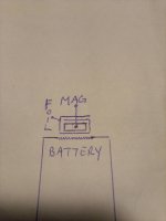
heres a sketch
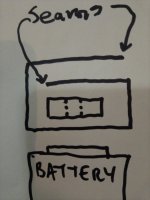
if your going to try 0.1mm copper not all the positive buttons are on the same plane, theyre cock-eyed this way or that way
i dont think that ladder style strip will work, the magnets wont compress the copper down like spot welding
but if you do a strip like this with tails to positive they will, i think my 0.1mm copper is another 3 weeks waiting on shipping so i havent tested the 10mmx1mm magnet on it
goatman said:Dak77 said:Do you have any idea how long the 10mm magnets hold their "strength" ? I understand that they are supposed to lose very little for like a hundred years normally, but does current passing through them change that ?
i havent seen any loss of strength, i limit my testing to 104f/40c, i think these have a working temperatur of 50 or 80 celsius
ive soldered to them and it lost half its strength
current doesnt pass through the magnet as far as i can tell
if you hear me say, "i had the seam down" it means the current was trying to pass through the conductive adhesive and discharge curve craps out
so i made to sure to mark the seam side up with black felt
heres a sketch
IMG_20210304_143141.jpg
if your going to try 0.1mm copper not all the positive buttons are on the same plane, theyre cock-eyed this way or that way
i dont think that ladder style strip will work, the magnets wont compress the copper down like spot welding
but if you do a strip like this with tails to positive they will, i think my 0.1mm copper is another 3 weeks waiting on shipping so i havent tested the 10mmx1mm magnet on it
IMG_20210304_143348.jpg
Oh yeh, duhh. I guess current wouldn't pass through them , being the higher resistance path. I'm not the sharpest tool in the shed sometimes.
goatman
10 MW
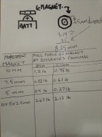
thinking of using a formula to calculate what magnet would be needed for 30amps
these magnets have a working temp of 80 celsius
the positive buttons are kind of convex
the circumference of the 2.5mm i.d. is 8.85mm
the 10x2.5x1mm magnet has 0.95 pound pull at 0.1mm and 1.22lb at 0mm
i know its good for 15amps at 0.05mm
10x5x2.5mm the id is 15.7mm, twice the contact area of the 2.5mm id
and twice the pull
i wonder if you can pull 2amps/mm of contact with 0.12lbs of pull force per mm
until 0.1mm copper comes i doubled up the tape by taping it to itself for strength
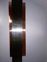
trace my cuts
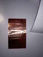
solder the wire
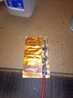
i shouldve double stacked 2-7.5mm magnets instead of 1-10mm
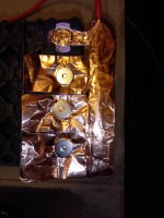
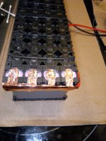
plasti dipped, should be ready to test tomorrow
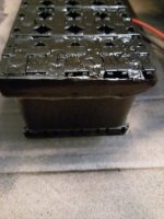
you can follow the testing over in this thread
https://endless-sphere.com/forums/viewtopic.php?f=14&t=109601&p=1622420#p1622420
these magnets have a working temp of 80 celsius
the positive buttons are kind of convex
the circumference of the 2.5mm i.d. is 8.85mm
the 10x2.5x1mm magnet has 0.95 pound pull at 0.1mm and 1.22lb at 0mm
i know its good for 15amps at 0.05mm
10x5x2.5mm the id is 15.7mm, twice the contact area of the 2.5mm id
and twice the pull
i wonder if you can pull 2amps/mm of contact with 0.12lbs of pull force per mm

until 0.1mm copper comes i doubled up the tape by taping it to itself for strength

trace my cuts

solder the wire

i shouldve double stacked 2-7.5mm magnets instead of 1-10mm


plasti dipped, should be ready to test tomorrow

you can follow the testing over in this thread
https://endless-sphere.com/forums/viewtopic.php?f=14&t=109601&p=1622420#p1622420
goatman
10 MW
G8trwood said:Curious if you could just use the magnet to hold a small wire that was then soldered to the bussbar sort of like the Tesla setup on the positive end
i was looking for a magnet like this that could hold a wire in its channel but couldnt find one
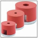
if youre not pulling amps, i stuck a copper wire in the freezer to shrink it then shoved it in the center hole, if you pull 10 amps the copper heats up, i think the copper linear expansion might shove the magnet off the surface and the discharge curve craps out. but i use these all the time
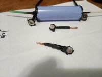
goatman
10 MW
instead of guitar string i was thinking of using nickel plated steel for the parallel
didnt know nickel was magnetic and stays magnetized
https://techiescientist.com/is-nickel-magnetic/
im playing with 5mm magnets right now and found 0.1x5x100mm pure nickel
https://www.amazon.com/dp/B07797WX16/ref=sspa_dk_detail_0?psc=1&pd_rd_i=B07797WX16&pd_rd_w=kBMvv&pf_rd_p=cbc856ed-1371-4f23-b89d-d3fb30edf66d&pd_rd_wg=HvCCM&pf_rd_r=MJSG5NGRZK34AGEY0KB8&pd_rd_r=858d157f-d866-4c5a-bb57-b74d3b099526&spLa=ZW5jcnlwdGVkUXVhbGlmaWVyPUFCQzAxRFMzOFdSNTAmZW5jcnlwdGVkSWQ9QTA0MzM4OTQyUFM3QlZESFI3UDNGJmVuY3J5cHRlZEFkSWQ9QTA2MzYwMTIxS0dOQVlQVEE0UEFHJndpZGdldE5hbWU9c3BfZGV0YWlsX3RoZW1hdGljJmFjdGlvbj1jbGlja1JlZGlyZWN0JmRvTm90TG9nQ2xpY2s9dHJ1ZQ==
if i bend it like a square sine wave
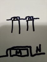
to parallel the 5mm foil magnets
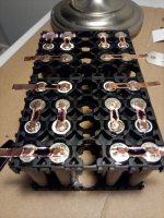
low profile
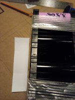
and have tabs for bms
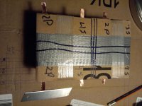
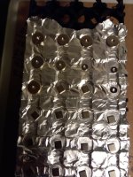
View attachment 1
used some acetone to get all the conductive adhesive off the copper, my digital calipers only start reading at 0.1mm
it took 4 layers of foil to read 0.1mm and 7 layers to read 0.2mm,
i think the copper foil is only 0.03mm thick, i know there is a copper slug tape on Amazon that is supposed to be 0.05mm
here it is
https://www.amazon.com/WINGONEER-Single-Side-Conductive-Shielding-Electrical/dp/B077M7BGYZ
with 10mm magnets (10+1+10+1+10mm) would be the equivalent of 10mm x 0.15mm copper strip
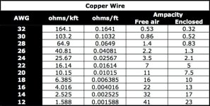
cut a square of foil 12.5mm x 24.5mm (7.5+1+7.5+1+7.5mm=24.5mm) rolled it into a wire thats roughly 12.5mmx1mm equivalent to 18 to 20 gauge wire, how many amps can a 1mm wire carry over 12.5mm?
didnt know nickel was magnetic and stays magnetized
https://techiescientist.com/is-nickel-magnetic/
im playing with 5mm magnets right now and found 0.1x5x100mm pure nickel
https://www.amazon.com/dp/B07797WX16/ref=sspa_dk_detail_0?psc=1&pd_rd_i=B07797WX16&pd_rd_w=kBMvv&pf_rd_p=cbc856ed-1371-4f23-b89d-d3fb30edf66d&pd_rd_wg=HvCCM&pf_rd_r=MJSG5NGRZK34AGEY0KB8&pd_rd_r=858d157f-d866-4c5a-bb57-b74d3b099526&spLa=ZW5jcnlwdGVkUXVhbGlmaWVyPUFCQzAxRFMzOFdSNTAmZW5jcnlwdGVkSWQ9QTA0MzM4OTQyUFM3QlZESFI3UDNGJmVuY3J5cHRlZEFkSWQ9QTA2MzYwMTIxS0dOQVlQVEE0UEFHJndpZGdldE5hbWU9c3BfZGV0YWlsX3RoZW1hdGljJmFjdGlvbj1jbGlja1JlZGlyZWN0JmRvTm90TG9nQ2xpY2s9dHJ1ZQ==
if i bend it like a square sine wave

to parallel the 5mm foil magnets

low profile

and have tabs for bms

View attachment 1
used some acetone to get all the conductive adhesive off the copper, my digital calipers only start reading at 0.1mm
it took 4 layers of foil to read 0.1mm and 7 layers to read 0.2mm,
i think the copper foil is only 0.03mm thick, i know there is a copper slug tape on Amazon that is supposed to be 0.05mm
here it is
https://www.amazon.com/WINGONEER-Single-Side-Conductive-Shielding-Electrical/dp/B077M7BGYZ
with 10mm magnets (10+1+10+1+10mm) would be the equivalent of 10mm x 0.15mm copper strip
cut a square of foil 12.5mm x 24.5mm (7.5+1+7.5+1+7.5mm=24.5mm) rolled it into a wire thats roughly 12.5mmx1mm equivalent to 18 to 20 gauge wire, how many amps can a 1mm wire carry over 12.5mm?

goatman
10 MW
goatman
10 MW
check this video out
https://www.youtube.com/watch?v=UBNjJDyS_ho
4 month wait for 5mm ring magnets
need 140 for the next pack build
have 120 on hand.......
ordered 100- square 5mm x 1mm magnets to use on the negative
use rings on the positive
bought 100mm x 0.1mm x 4mm pure nickelstrip to parallel connect the square magnets/bms lead
0.1mm copper i get by April.13 from Amazon
just waiting for materials to arrive
goatman
10 MW
equalizing some batteries, didnt want to use copper
grabbed tinfoil
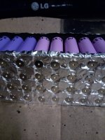
i think i read somewhere heavy duty foil is 0.05mm
going to see what aluminum foil can do
from this article
https://www.anixter.com/en_us/resources/literature/wire-wisdom/copper-vs-aluminum-conductors.html
i get this
the copper im using is 0.03mm
heavy duty aluminum foil 0.05mm
should work
measured the foil, its 0.03mm thick, same as the copper
doubled it up
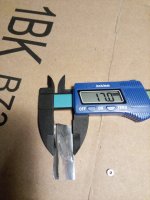
5mm magnets
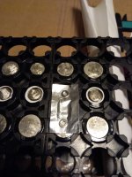
fold it over
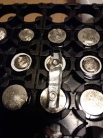
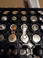
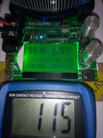
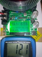
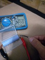
at 7.5 amp discharge the curve was no good and the aluminum ran 10f hotter than the copper
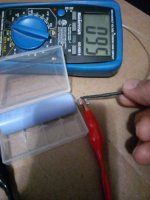
at 5amp discharge the curve was good and the aluminum ran 8f hotter than the copper
the 5mm square magnets for the nickelstrip bms connection arrived
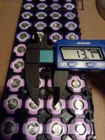
changed the gap of the copper tape from 12.4mm to 13.7mm (1 inch overall width)
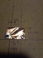
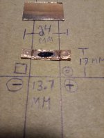
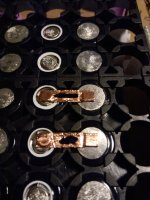
no nickelstrip yet so used paper to show how it would lay centered in the row
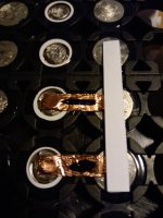
the other thing i should mention, i grind the spotwelds off these used cells which creates a rough surface
once these magnets sit on the battery for about 12hrs
you cant get them off with your fingers or other magnets
they dont slide around, you cant move them
theyre locked on and you need tweezers to grab a corner to get them off
grabbed tinfoil

i think i read somewhere heavy duty foil is 0.05mm
going to see what aluminum foil can do
from this article
https://www.anixter.com/en_us/resources/literature/wire-wisdom/copper-vs-aluminum-conductors.html
i get this
Aluminum has 61 percent of the conductivity of copper, but has only 30 percent of the weight of copper. That means that a bare wire of aluminum weighs half as much as a bare wire of copper that has the same electrical resistance. Aluminum is generally more inexpensive when compared to copper conductors.
the copper im using is 0.03mm
heavy duty aluminum foil 0.05mm
should work
measured the foil, its 0.03mm thick, same as the copper
doubled it up

5mm magnets

fold it over


at 7.5 amp discharge the curve was no good and the aluminum ran 10f hotter than the copper

at 5amp discharge the curve was good and the aluminum ran 8f hotter than the copper

the 5mm square magnets for the nickelstrip bms connection arrived
changed the gap of the copper tape from 12.4mm to 13.7mm (1 inch overall width)


no nickelstrip yet so used paper to show how it would lay centered in the row

the other thing i should mention, i grind the spotwelds off these used cells which creates a rough surface
once these magnets sit on the battery for about 12hrs
you cant get them off with your fingers or other magnets
they dont slide around, you cant move them
theyre locked on and you need tweezers to grab a corner to get them off

What do you think happens during the 12hrs for the magnets to stick so much better?goatman said:once these magnets sit on the battery for about 12hrs
you cant get them off with your fingers or other magnets
goatman
10 MW
99t4 said:What do you think happens during the 12hrs for the magnets to stick so much better?goatman said:once these magnets sit on the battery for about 12hrs
you cant get them off with your fingers or other magnets
not sure
the slug tape has conductive adhesive on it, so theres a layer of adhesive between the magnet and copper. i dont know if the adhesive is being displaced in the roughness of the contact surface for a stronger connection???
goatman
10 MW
kilou said:@goatman Great tests! Did you test the temperatures with the PlastiDip or without it? Also, what do you think about covering the vent holes on the positive terminal with PlastiDip? Is this not something to worry about?
where i live im more worried about keeping my batteries warm, my 25r packs ive been using for a year with plastidip. never had a overheat heat problem running at 7 or 10 amps
covering the vent holes
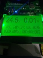
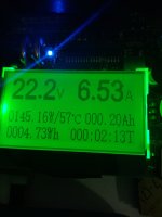
if you see my battery tests like the 40T or p42a, mnke 26650, those were done with the magnets and plastidip at temps of 102F to 104f
i use samsung 30Q and 25R, if i youtube people shorting out their cells, i dont see them blowing up like the mnke 26650 does
anytime ive had a p-group go bad, my battery just stopped working
no fire, no venting, no signs of anything except a p-group at 0 volts
cut the 2 inch slug tape 12 inches long and then cut it into 2-1 inch wide strips
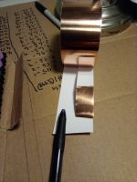
that did 1 side of the battery with 5mm magnets
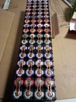
im using salvaged cells and wasnt all that happy about using the flat square magnets, but if i push on each of the 4 corners of the magnet and if i see the copper with the black mark, move
then i know the magnet isnt sitting flat and only has 3 corners touching instead of 4
its really teetering on 2 points with 3 points touching
in the picture above youll see the magnets arent completely inline, thats why.
i wanted to make sure there was a solid connection
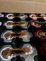
the 4mm nickelstrip came in
grabbed how many i needed and put them on a stack of magnets to see how magnetic they became before putting them on the pack, didnt notice anything really
they do stick to the magnets really well though
nice low profile
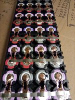
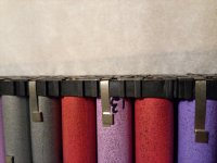
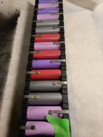
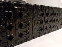
goatman
10 MW
using up my 10mm magnets
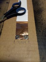
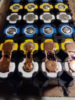
heres a side by side comparison of the magnets ive used so far
10mm, 7.5mm and 5mm
10mm and 5mm side by side
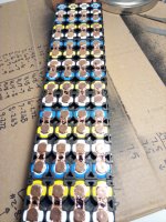
changed the copper to 31mm wide from 30mm
when the copper pinches to fit in the 8mm gap, it was a little short
nickel strip
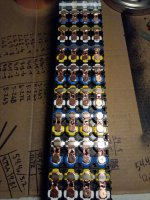
plasti dip this side before working on the other side
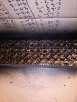

heres a side by side comparison of the magnets ive used so far
10mm, 7.5mm and 5mm

10mm and 5mm side by side

changed the copper to 31mm wide from 30mm
when the copper pinches to fit in the 8mm gap, it was a little short

nickel strip

plasti dip this side before working on the other side

Ianhill
1 MW
- Joined
- Sep 25, 2015
- Messages
- 2,871
I like this alot ive had a quick read through and i teally pike the idea there no special ewuipment needed like a traditional nickel spot weld amd the resistance is less only thing i spotted was the insulator ring on the cell top is missing you only have the shrink jacket stopping a short id been more happy with 2 levels of protection on that area so many fires have started from a faliure in that area of the pack.
goatman
10 MW
yes
im not really worried about it with the 5mm or 7.5mm magnets because the plasti dip gets in under there, when you spray it on, theres a chemical reaction, its bubbling and flowing into all the cracks, the copper tape is soft with no sharp edges and pretty flexible
but the 10mm magnets i have to squish the copper into the 8mm series cell holder gap, the plasti dip is not getting in under there
i should of put a little dab of silicone there
the insulator rings ive measured only have a 9.5mm inside diameter, smaller than the od of a 10mm magnet
ran out of plast dip last night, this is a thin first coat of the 10mm showing how it gets squished in
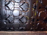
not really crazy about using the 10mm magnets on 18650s, theyre not needed
10mm magnets id use for high amps on 21700 or 26650 cells with bigger positive buttons, 18650s are about 8mm od button
for 18650 high power cells id look for 0.05mm copper tape and 7.5mm magnets
anything under 7amp max id use the 5mm magnets
im not really worried about it with the 5mm or 7.5mm magnets because the plasti dip gets in under there, when you spray it on, theres a chemical reaction, its bubbling and flowing into all the cracks, the copper tape is soft with no sharp edges and pretty flexible
but the 10mm magnets i have to squish the copper into the 8mm series cell holder gap, the plasti dip is not getting in under there
i should of put a little dab of silicone there
the insulator rings ive measured only have a 9.5mm inside diameter, smaller than the od of a 10mm magnet
ran out of plast dip last night, this is a thin first coat of the 10mm showing how it gets squished in

not really crazy about using the 10mm magnets on 18650s, theyre not needed
10mm magnets id use for high amps on 21700 or 26650 cells with bigger positive buttons, 18650s are about 8mm od button
for 18650 high power cells id look for 0.05mm copper tape and 7.5mm magnets
anything under 7amp max id use the 5mm magnets
Hummina Shadeeba
1 MW
Doesn’t the resin sneak between the copper and cell to some degree? The magnet maybe has a strong enough pressure to keep it out
Ianhill
1 MW
- Joined
- Sep 25, 2015
- Messages
- 2,871
I sat on my bog and i thought this.
What if the magnets and the plastic dip is complete gone just copper sheets in a 3d printed plastic enclosure.
The base of this enclosure could have micro dimples where the battery's ends meet under the copper to give lots of points of pressure or a large dimple depending what carrys current best.
These 2 opposing pieces could be blasted with nitrogen and sonic welded togetether for an airless enviroment around the cell if needed or just bolted.
Beauty of this is to remove heat from an 18650 the junction point is its lid the copper plates could be each liquid cooled from above meaning the cells never touch a fluid as such and sit in an airless enviroment with a non conductive enclosure but have liquid cooling and copper links.
Im not to sure if airless enviroment is needed for corrosion resistance or if a 3d print could retain nitrogen at all but from there injection moulding files for a local supplier or what evers needed to keep it in the hobbiest hand.
goatman
10 MW
when i used wire it would get right in but the contact points were fine
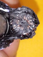
look at this post from earlier
https://endless-sphere.com/forums/viewtopic.php?f=14&t=106190&p=1569054&hilit=elastic#p1574355
you can see it gets in between the smooth cell surface and copper in the surface irregularities
but the connection is fine, i think the picture was taken after about 200 cycles
on a smooth surface the magnet will move if you shove it
these battery builds ive roughened up the surface
magnets dont move at all and are hard to remove now
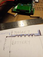
in betwwen the magnet and the battery is the copper foil with the adhesive on 1 side
i think whats happening is the adhesive is being displaced a little into the lows
ill draw an exagerated picture

Hummina Shadeeba
1 MW
ive got some of the tape with adhesive and its cheap and easily gotten and a nice shape but the adhesive always seems an obstacle and such thin copper. it sits unused.
if only there was some way to get assured a clean contact I'd be sold. it may work as is and maybe would be no problem in any iteration but if only...would be the clincher. Maybe a spot of conductive paste between all contacts would keep them assuredly clean. Or maybe with compression contacts its so much more contact and higher conductivity than welds anyway?
have so many questions an accurate resistance meter could answer but still to cheap to buy it. whats the best deal? someone posted one for 40$ they recommended but cant find it.
goatman
10 MW
i think PWD liked this one
https://www.amazon.com/YR1035-Internal-Resistance-Battery-Lithium/dp/B08R7P78VC
https://www.amazon.com/YR1035-Internal-Resistance-Battery-Lithium/dp/B08R7P78VC
goatman
10 MW
spinning magnets mentions poron foam
https://endless-sphere.com/forums/viewtopic.php?f=14&t=84680&p=1624207&hilit=poron#p1624207
https://endless-sphere.com/forums/viewtopic.php?f=14&t=84680&p=1624207&hilit=poron#p1624207
Hummina Shadeeba
1 MW
Without a good resistance tester like one of those posted how good all these connection methods are is unknowable. Or could figure another way to do an accurate resistance test.
I designed another method using 3D prints and rubber bands. Works fine but in use found the tight case it’s put in effected the connections and also a lot of work and shorting risk when taking it apart or putting together
I designed another method using 3D prints and rubber bands. Works fine but in use found the tight case it’s put in effected the connections and also a lot of work and shorting risk when taking it apart or putting together
Similar threads
- Replies
- 3
- Views
- 757
- Replies
- 13
- Views
- 4,324
- Replies
- 1
- Views
- 2,475
- Replies
- 15
- Views
- 2,825


