APL's V4 Cruiser Build.

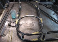
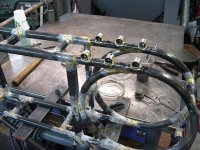
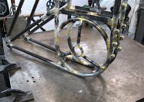
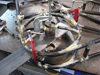
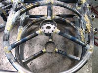
I have the J tubes brazed in, and have a pretty good idea of what the ring miters should look like now. If I make the flute
about 55mm long, it puts the 10" ring at 90 degrees, so that makes it easier to file the rest of them.

Flute = 55mm.jpg

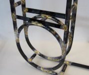
The ring didn't turn out too bad, and I'm happy with that,.. not perfect, but then it doesn't have to be either, it's all for the
art of it. :)

Ring brazed..jpg

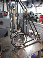
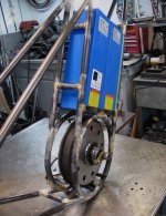
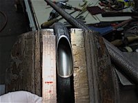
Finally, we get to see what the motor looks like in this thing!

Motor fit..jpg

Hmm... It's pretty obvious to me that I'm going to need a much bigger motor! :D :thumb:
(just kidding)
 
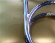
Couldn't resist finishing out a ring joint, to see how it will look. Fillet brazing is a lot of work for sure, but it can look
sweet! All that will come towards the end though, just before paint.

Finished ring joint..jpg

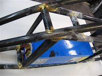
The battery box bridge looks like it's bullet proof! I'm pretty sure that these batteries aren't going to go anywhere. The
box will be lined with 1/4" fiberglass panels, and foam rubber. Theres going to be some outer metal side panels too.

Battery box bridge,.jpg

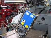
Finally able to put the batteries in it and see how they fit. Looks like theres plenty of room for everything, and it's all
working out pretty good so far. I've got my fingers crossed on the the chain line though, she's going to be tight here and
there, I'll have to wait until the motor and cranks are mounted in it, to get a good look at it.

Battery space check..jpg

She's starting to look a little more serious. Dang thats a lot of battery power! (2 x 26 ah) Definitely not in Kansas any more.

V4 Loaded..jpg

The battery box will be about 10" x 13" x 4", with a little extra room on top for wires and connectors.
Some prism cells would look real nice in there. 8)

Up next,.. finish the B-box top, and braze in all the upper tubes and braces.
 
Thanks guys, it's starting to look a little dangerous! :thumb:

Not quite ready for a post, but I'll show what I have anyway. Summer has a way of splitting your time in five different
directions, plus, I'm in a fairly hard part of the build.

These girder frames have a multitude of connections in one place, which makes brazing a challenge sometimes, and
the tubes have to go in a certain sequence or a tube can get locked out.

But, I have the top battery box brazed together at least, and the middle top tubes should go in a bit faster now that
thats all done.

Top bat. box..jpg

The two bridges on the top are where the seat pivot gets attached, and the rear of the two middle top tubes.

IMG_2742 (1) copy.jpg

Not too exciting and kind of a drudgery, but needs to be done. Once this is done, and I can get the seat and front forks on
it, things will get interesting.
 
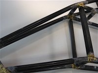
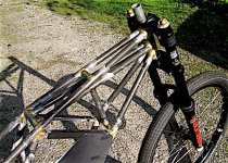
Finally have the front mid-tubes brazed in,.. after quite a bit of effort. Have to say though, it looks to be a massively
strong front end.

Front mid-tubes..jpg

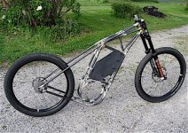
And a shot of the bike with the wheels on it. I don't know what kind of tires will eventually wind up on it, I might even
opt for a 29er on the front and a fat-bike tire in the back, but 2.5's will do for now.

Up on two wheels..jpg

Once I get the rear mid seat stays in, I can start to work on the seat swing arm, and lower shock brackets.
But, she's starting to look like a bike at last! :)

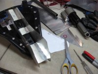
I'm still working on the side plates, and not sure what it's going to wind up with yet, but at the moment I'm thinking two
3/8" aluminum diagonal plates,.. something like I have mocked up in the photo. I need to give the box some lateral
strength, and they're part of the frame structure. I also need to try to diminish the big 'square' battery box look.
 
Well, I've changed my mind on the side plate a few more times, so who knows... now I'm thinking instead of trying to hide
the box, maybe I should feature it with a little fear factor. :bolt:

I have the rear mid tubes and bridges in, so the frame skeleton is complete, and now it's all about brackets & braze-on's.

Mid stays in..jpg

Built like a truck, this thing is a beast! I get the feeling that I'm building a Dragbike. :shock:
Hmmm, Street & Strip cruiser?

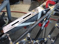
I've been using aluminum roof flashing for mocking up brackets,.. it cuts with a scissors and holds a shape pretty good.

Seat swing arm bracket..jpg

The seat swing arm bracket is just getting started, so theres a few mods to make yet. This one is steel, but down the road
I'll machine some aluminum for a nicer look.
It'll be nice to get the seat on it, and finally check out the fit and feel of the ride. 8)
 
Progress is slow,.. the swing arm, mount, & shock mount all have to get built together more or less, and clamped to
the frame so I can sit on it and check the fit.

Seat position.jpg

At least I have that done, and the swing arm is on the way to being completed. Lots of steel to be trimmed off yet,
cut-outs and shock holes, and some adjuster screws to adjust the bottom-out point, but a wide flat support to rest
the seat on.

Swing arm progress..jpg

I gave it 2" of seat movement front to back, and theres going to be plenty of shock adjustment points to dial in the
spring action. Way over built, as usual, but I expect it to work really smooth, with no rattles or sway for a good long time.
 
Holy Molly - the master is back to work! Anything you do is quite inspirational. I followed the entire thread about your axial flux motor - just O M G. Mad skills. Too bad there is a ocean between us (or thank god!) or I'd instant come visit you and try to soak up as much as possible.
If you don't mind me asking: why brazing and not welding ? Seems to me that modern TIG welding goes faster for a stronger and lighter endresult.
 
Just getting caught up on the last few updates, it looks great.

I like the idea of the aluminum roof flashing for mockups and templates will have to steal that. I have a top tube idea for a part made from formed sheet and this will make it much easier to mock up and flesh out if the idea will work.
 
Thanks guys! :)

Answering your question qwerkus, Ive been asking myself that throughout this build,.. so much of this could be Tig welded
much easier!

If it was a regular 'diamond' large-tube frame, brazing would be no big deal, but a small tube girder frame is best Tig
welded I think, or at the least a little of both. It's just that I've been brazing since 1976, so thats always my go to method.

So many tubes and brackets in one spot means re-heating bigger and bigger connections,.. well you have to build it to find
out I guess. Theres a lot of things I'm learning about this bike that will be reflected in the next version for sure.
Your right, it's time to get the Tig welder.

Thanks Lightbluemk2, she is a solid bike! A bit too solid actually, I figure this frame is about two times stronger and
heavier than it needs to be, and getting heavier all the time. Not too happy about that, but it doesn't hurt anything I guess,
and it's always better to overbuild at first, and work on getting things lighter later.

I'll be getting to the drive system pretty soon, but for starters, the motors going to drive a rear der and cluster, and the
front cranks will drive the motor via a single speed freewheel on the motor. The cranks are short for foot clearance to the
front wheel and ground, and the chainring will be just big enough to drive the bike in case of system failure.

This makes it legal as an electric bicycle in the USA, and I can ride the bike lanes and some bike paths. It's not intended
to be an exercise bike, like most e bikes, but rather just a form of clean transportation to keep the car in the driveway
a little more. The huge battery capacity should give it about a 60 mile range, but of course that remains to be seen.
In the end, I hope to solar charge it so it will be grid free.

That being said though, it also has the potential for huge power, and I don't know how long the der/cluster system is
going to last. So, I'm making plans to maybe go single speed drive with an 1/8" chain and a White Industries ultra heavy
duty freewheel in back.

The trouble with going single speed is finding the gear ratio that gives a good starting torque and the top speed I want,
28 - 30 mph. That would be about 1 to 1, and I lose the advantage of mid drive, and need to go with higher voltage to
gain more gear ratio.

Anyways, blah, blah, sorry to ramble on... this stuff goes through my head all day, and I'll get there soon enough. The
fact is, there are many options, so it will be interesting and fun to figure out.
 
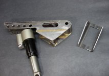
Seat swing arm is done and drilled full of holes.. still needs to be made out of aluminum, but at least I have a good
pattern to work with, and something to dial the system in with for now. I added some skirts on the bottom that hold the
12mm set screw 'stops', and help to stabilize the swing arm.

Seat-arm complete..jpg

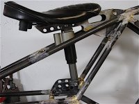
The no-name shock came from the parts bin at the local bike shop, and I drilled out the nitrogen plug on the bottom,
so now It's just a straight up air shock. I've looked around for generic air shocks, but there isn't much out there that looks
and fits as good as these things, and the cost wasn't much.

The last bike didn't have the shock positioning options that this one does, so I'm hoping to be able to dial it in a bit better
this time around.

Seat suspension finished.jpg

At ant rate, I'm finally finished with that project and able to move on to the next one, which is the front bottom bracket
and motor mounts. Then I can finally get my eye on the chain line and see what kind of mess I have there.

I think after that, it will be the end of the brazing except for a few braze-on's, and I can dip tank this thing and finally get
all the flux off of it, and start the finishing process.

Yee-ha! After that is paint, and I get to put parts on it! :D
 
Most of the time is spent just trying to figure out what to do or how to do it. I have everything drawn out, but a lot of
times the actual building is subject to change when I get there.

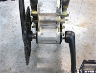
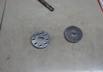
The front eccentric BB was going to get brazed directly to the frame, but I opted for a bolt-on idea that will allow me to
change out the system, or go with an aluminum unit in the future. I silver brazed six 3/8" bosses onto it so they can be
easily taken off again, if need be.

IMG_2768 (1) copy.jpg

It also occurred to me that I could maybe mount a powered mid-drive set up on there and get some real pedal assistance,
and a larger chainring. Crazy thought though. :wink:

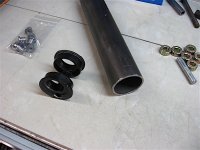
I bought a cheap aluminum eccentric BB on the Bay,.. don't know what it came from, I think maybe BMX,.. and found some
DOM tubing thats real close to the ID I need. The tube is mega thick though, so I'm going to mill some slots in it to cut the
weight a bit, and make it easier to braze. The set up is way cheaper than buying a tandem BB, and I can make several more
from the tube. (2-3/8" OD)

Eccentric BB & tube..jpg

All this should get me in the ball park, and I can always change it out for whatever reason.
 
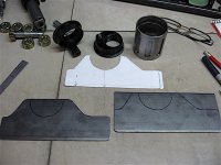
Cut and turned the tube and milled some slots in it for a little flare. Sketched a pattern from the drawing and scribed
it out on some 1/8". Added a couple of bridges to give it some body, and brazed it all up.

Shell and bracket..jpg

Turns out, the shell and the down tube spacings are almost the same, so I had to put some bends in the plates. The
controller matches up with the top, and there might be a kickstand that bolts to the bottom,.. not sure about that yet.

This is the first attempt anyway, it could use a few more holes in it here and there, and some better bolts, but this will
do for starters. Definitely rock solid though, and I'm liking the idea of being able to change it out. :)

BB assembly mounted..jpg

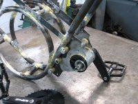
The front chainring needs to go right up against the down tube for a tight chain line to the motor. I forgot about the
crank spider thickness though, and it's hitting the mounting boss's about 3mm. I think I can counterbore some flat head
allen's in there, and squeak by, otherwise I'll have to braze a few threaded bungs on it, and bolt them from the inside.

Spider - boss..jpg

About half way through, I realized that it doesn't really need to use an eccentric BB,.. if I slot some of the mounting
holes, the whole assembly can tilt in an arc to tighten the chain. :roll:

Projects done though, so motor mounts are up next.
 
I settled on the idea to use a piece of tubing for the center of the motor mount, and I'll silver braze a 1/4" thick slotted
axle mount into it. That way it can be removed/replaced for whatever reason, and makes it easy to align parallel to the
motor. I decided to braze in the drive side mount arms, and bolt in the non-drive side.

Motor mount arms..jpg

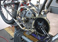
The chain line looks like it's going to work out with a bit of adjusting, so thats a big relief. I'll lose the inner and outer
cogs in back, but I could never use them before anyway,.. and frankly, the bike only needs 2 - 3 speeds to work well, so
7 cogs are more than enough for now. I can always swap out the cassette system for an IGH hub, but I'm still not sure
how long they will live under this kind of load.

V4 Chainline check..jpg

The motor's not positioned correctly in the picture, I'll need to get the other mount done before I can get a good photo
of that, but at least you can see how the drive system works out. One good thing is, neither chain needs to be broken
to get them out of the frame, and all the links can stay connected.
 
Still plodding along,..I hoped to have a lot more done, but life has different ideas. The left motor mount is a lot more
involved, with frame inserts and bolt lugs, but I got her done.

Left motor mount..jpg

Moved on to the axle mounts, and torched out some .250" thick steel washers, milled an 11mm slot and drilled some holes
to help with brazing.

Axle mount..jpg

Once I get these guys silver brazed in, I can move on to the disc brake mount and side plate mounts, which should be
easy, and then I can finally dip tank this beast and get all this crusty flux off of it!

Ready for silver..jpg

Can't wait to start grinding on it, and drag it into the paint booth!
 
I was wondering how you'd tension the first chain. Eccentric BBs are clean though how do you plan to clamp yours ? Usually they'd cut though the entire length of the BB tube and weld some bolt joints on.
 
Good question qwerkus.

This eccentric is turning out to be a disappointment, theres a bolt on one side that goes all the way through and is
'supposed' to tighten the two halves together, but the BB cups push the two halves outward when it's tightened. :roll:

The solution was going to be a threadless BB that would clamp it together, but I need a 124+mm axle and most offerings
are off-shore and more $$ with shipping. (unless I can swap out axles)

Sooo,.. I guess I'll run a few more small bolts through it for now to get it up and running. Or, like you say, slot and braze
some clamp bolts on the shell sides. :thumb:

What I should do is just build another assembly with a normal BB shell, and slot the upper mounting holes for tensioning.
Or, buy a decent eccentric assembly,.. haven't had a lot of experience with them, but I think they tend to corrode and
get stuck with time... maybe not.

I don't want to get too hasty yet though, because I want to ride the bike for a while and see if the crank position is in the
right spot, or if it needs to be moved a bit. I wouldn't mind trying some longer crank arms on it too, and that might
change position as well.
 
APL said:
Or, buy a decent eccentric assembly,.. haven't had a lot of experience with them, but I think they tend to corrode and
get stuck with time... maybe not.

This. Just got a 15 year old bike with an eccentric bb; had to heat treat it to finally be able to rotate it again. Funny thing is the manual I found about that bike, saying explicitly you have to grease the bb "on regular basis". No thanks.

I think the only clean way to do it is by moving the entire BB cage, either by sliding it, or rotating it like you suggested, which requires only 2 slotted bolts. Just make sure to design it so as to pedal against the un-slotted bolt and not the opposite :shock: .
 
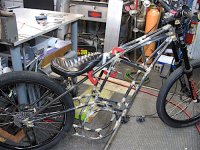
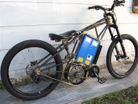
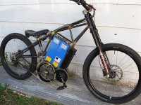
Finished up the brazing, dip tanked it, and hung most of the parts on it for a couple of pictures before I start finishing
it out. It's looking pretty raw, but at least I can finally see it's full form.

V4 Back .jpg

It doesn't look like I had hoped for, and it's looking a little 'utilitarian' or even military to me, and I wanted 'Muscle Cruiser'.
Maybe some straight bars will help.

But, I know I have to many tubes in this one,.. the rear mid-stays and the top rings can go, as well as some front mid's.
I should bring the seat mount down, and shorten the rear end too. Oh well, it's like a tailor adjusting a suit... I'll get it.

V4 Front .jpg

Well, I'll just keep plodding along, maybe some paint and the battery side plates will help me get over it. I was planing on
building a second bike later on, so I can make the changes on that. I need to get this thing done so I can get back on the
road!

On the plus side, the seat suspension turned out to work awesome, best action yet, and super posh!

Next is the finishing, paint, making side plates, figuring out a dash, and the wiring.
 
No, not done, still have a ways to go yet. Thanks for the thumbs up though! Need to get it painted, and go through all the
electrical stuff,.. these are just mock photos, so I can get an idea on what to do next and what to change to get the 'look'
that I'm after.
 
I reckon
1) paint it, will look so much nicer without the flux and mess
2) box in the battery. The blue is the elephant in the room
3) Shine up the motor to make it stand out
4) the controller... Good knows what it is but it's hideous and huge. Surely there's a smaller one.
5) the mount for the shock, once you've chosen a position, get rid of the fussy holes
6) The cheap crappy chain set looks like it.
7) bars and stem are just not tidy, look at downhill bike parts, much sleeker with lower rise and a smoother stem. 888 forks have a direct mount stem option that would look much nicer

It'll look great once tidied up! The shape is fine
 
Back
Top