New "TSDZ2 Torque Sensor Central Motor"

Akita said:
Elinx said:
Akita said:
Tested my new TSDZ2 v2 36v ... the display showed 5 bars out of 6 for the battery. No help from the engine.....
No help of the engine? How do you test the tsdz2?
36V is just a nominal Voltage for calculating (sort of average value)
A just fully charged 36V battery in good condition measures 42V and can be drained to about 30V.
If you start the display, the controller started too, so you battery draines also. How much depends again of the condition of it.
More important is the distance, you can go with a full charge and working engine.
I have a hill and there were no problems to the store.
Felt directly in the pedals that the engine helped.
Tried ECO, TOUR, SPEED and TURBO.
Felt it was different.
On the return trip also a hill but without the help of the motor.
The display shows completely OK on both occasions.
5 bars when I cycled to the store and 5 at home.
Tried ECO, TOUR, SPEED and TURBO.
No difference, Same as OFF.

39v after full charge displayed? could you have a bad charger or pack out of balance?
 
Manbeer said:
Akita said:
Elinx said:
Akita said:
Tested my new TSDZ2 v2 36v ... the display showed 5 bars out of 6 for the battery. No help from the engine.....
No help of the engine? How do you test the tsdz2?
36V is just a nominal Voltage for calculating (sort of average value)
A just fully charged 36V battery in good condition measures 42V and can be drained to about 30V.
If you start the display, the controller started too, so you battery draines also. How much depends again of the condition of it.
More important is the distance, you can go with a full charge and working engine.
I have a hill and there were no problems to the store.
Felt directly in the pedals that the engine helped.
Tried ECO, TOUR, SPEED and TURBO.
Felt it was different.
On the return trip also a hill but without the help of the motor.
The display shows completely OK on both occasions.
5 bars when I cycled to the store and 5 at home.
Tried ECO, TOUR, SPEED and TURBO.
No difference, Same as OFF.

39v after full charge displayed? could you have a bad charger or pack out of balance?
Use it for another bike as well.
No problem.
Fully charged it is 42 volts.
 
Akita said:
.....
No help on level ground home but to the store.
Then a small hill at the end of the journey. No help.
Never cycled over 25 km / h
Let me summarize
Your engine did assist in the first place, but on the way back it doesn't anymore.
Do I understand well that the engine isn't working at all now, but you can read the speed.

I ask because the reason could be the magnet of the speedsensor, but normally you can't read the speed in that case.
 
Elinx said:
Akita said:
.....
No help on level ground home but to the store.
Then a small hill at the end of the journey. No help.
Never cycled over 25 km / h
Let me summarize
Your engine did assist in the first place, but on the way back it doesn't anymore.
Do I understand well that the engine isn't working at all now, but you can read the speed.

I ask because the reason could be the magnet of the speedsensor, but normally you can't read the speed in that case.
Magnet of the speedsensor 5 mm from the mark on the sensor.
The display showed speed but no power from the engine.

Have now traveled the same distance again.
No problem.
Battery now stacks 4.
What I did the first time was that I disconnected the power from the battery when the display was on.
Now I left the power on and turned it OFF on the display.
Maybe this is what made it not work.

Now to another question.
You can set the speed in two menus.
One where it says 25 km/h and where I can choose ON/OFF.
Then the menu for speed Sd.

When 25 km/h is on ON, I can select the speed under Sd
When 25 km/h is set to OFF, SD only shows dashes.

Can't find manual where this is described.
 
Akita said:
Elinx said:
Akita said:
.....
No help on level ground home but to the store.
Then a small hill at the end of the journey. No help.
Never cycled over 25 km / h
Let me summarize
Your engine did assist in the first place, but on the way back it doesn't anymore.
Do I understand well that the engine isn't working at all now, but you can read the speed.

I ask because the reason could be the magnet of the speedsensor, but normally you can't read the speed in that case.
Magnet of the speedsensor 5 mm from the mark on the sensor.
The display showed speed but no power from the engine.
5mm is too close, 8-10mm is good and yes you will get exactly the symptoms you describe with a magnet set too close, that of intermittent power from the motor. The later OSF versions have a fix for this and the magnet can be set from about 2 - 10mm without problems.
 
Waynemarlow said:
Akita said:
Elinx said:
Akita said:
.....
No help on level ground home but to the store.
Then a small hill at the end of the journey. No help.
Never cycled over 25 km / h
Let me summarize
Your engine did assist in the first place, but on the way back it doesn't anymore.
Do I understand well that the engine isn't working at all now, but you can read the speed.

I ask because the reason could be the magnet of the speedsensor, but normally you can't read the speed in that case.
Magnet of the speedsensor 5 mm from the mark on the sensor.
The display showed speed but no power from the engine.
5mm is too close, 8-10mm is good and yes you will get exactly the symptoms you describe with a magnet set too close, that of intermittent power from the motor. The later OSF versions have a fix for this and the magnet can be set from about 2 - 10mm without problems.
Now fixed to 9 mm.
Do you have any explanation why there are two speed settings?

I have read two installation manuals and the distance should be 3-5 mm.
Then I set it to 5 mm.
 
Akita said:
Waynemarlow said:
Akita said:
Elinx said:
Let me summarize
Your engine did assist in the first place, but on the way back it doesn't anymore.
Do I understand well that the engine isn't working at all now, but you can read the speed.

I ask because the reason could be the magnet of the speedsensor, but normally you can't read the speed in that case.
Magnet of the speedsensor 5 mm from the mark on the sensor.
The display showed speed but no power from the engine.
5mm is too close, 8-10mm is good and yes you will get exactly the symptoms you describe with a magnet set too close, that of intermittent power from the motor. The later OSF versions have a fix for this and the magnet can be set from about 2 - 10mm without problems.
Now fixed to 9 mm.

I have read two installation manuals and the distance should be 3-5 mm.
Then I set it to 5 mm.
 
Akita said:
.....
Do you have any explanation why there are two speed settings?....
Normally one for setup the max. bike speed and on/off for walk assist (6km/h)
 
I wounder if we could 3D print a TSDZ2, reusing the torque sensor, the motor controller V2 board but with following changes:
1. add a belt to have a silent motor
2. reduce the motor weight by using a smaller motor

OR

3. increase the motor power by using a more powerful motor.

What I wish to improve on TSDZ2 is being more silent and have a smaller and lighter version (200W max continuous motor power) for a gravel bike as also a more power version (1500W continuous) for a cargo bike.

There are people 3D printing mid drive motors structures with carbon fiber PETG, using small but powerful 3kW motors and with a belt:


[youtube]I8X73-BKbH8[/youtube]

[youtube]OUKnGcXFA3Q[/youtube]

And there are also people 3D printing their own frame lugs using the carbon fiber PETG and building their own bike, seems there is a good potential to 3D print in carbon fiber a mid drive motor case and use our own motor, more powerful or lighter: https://www.thingiverse.com/thing:892442


[youtube]ni6o4rolPcg[/youtube]
 
I think the idea of printing our own structure may be a little overkill, the basic shell doesn't weigh anymore than a printed version and in some ways will probably weigh less. So where's the weight saving to come from. The controller is a fixed weight, the torque sensor and axle is to be used again.

So the only savings would be a lighter and smaller motor and somehow changing the one heavy component we have, the main gear. Its on this side of the motor that all the weight savings are to be found. Belt drive necessarily doesn't mean quiet after all the latest Bafang M600 and M500 are rumoured to be quieter than the Brose motor with their latest PEX main gear that they are now using from the factory. All the initial problems they had, which meant they changed to a steel gear from the PEX, were no differnet than the TSDZ2's early problem of stripping the blue internal gear, which was one of the main reasons the OSF firmware was developed by Buba and Casainho amongst others. How many blue gears do I now strip, very rarely and only if another mechanical problem such as chain suck in the winter mud causes the problem.

My guess is its this one area, the weight of the main gear and getting a good reliable PEX gear in there may well give you all you want.
 
Waynemarlow said:
I think the idea of printing our own structure may be a little overkill, the basic shell doesn't weigh anymore than a printed version and in some ways will probably weigh less. So where's the weight saving to come from. The controller is a fixed weight, the torque sensor and axle is to be used again.

So the only savings would be a lighter and smaller motor and somehow changing the one heavy component we have, the main gear. Its on this side of the motor that all the weight savings are to be found. Belt drive necessarily doesn't mean quiet after all the latest Bafang M600 and M500 are rumoured to be quieter than the Brose motor with their latest PEX main gear that they are now using from the factory. All the initial problems they had, which meant they changed to a steel gear from the PEX, were no differnet than the TSDZ2's early problem of stripping the blue internal gear, which was one of the main reasons the OSF firmware was developed by Buba and Casainho amongst others. How many blue gears do I now strip, very rarely and only if another mechanical problem such as chain suck in the winter mud causes the problem.

My guess is its this one area, the weight of the main gear and getting a good reliable PEX gear in there may well give you all you want.
Yes, main gear is really heavy.

The other advantage would be for a more powerful motor.
 
VLCD5
There is a menu where I can turn off 25 km/h. If I set it to OFF, I will get engine power over 25 km/h.
I get no extra engine power when I set the setting to OFF above 25 km/h.
What's wrong?
https://www.youtube.com/watch?v=nRYwzLWfvXc
 
Akita said:
.....
Are there any values where I can see how torque and cadance interact?....
Not that I know of.
The calculation formula of these sensor values are not published.

Akita said:
....
What's wrong?
...
Nothing, the new controller V2 is limited to 25 km/h (special for the EU market)
That youtube video is for the "old" controller V1 which is limited to 45km/h, because on international market the speedlimits are different.
If V2 controller will be sold international, there is a chance that the speedlimit will be higher too.
 
Hi, just registered in order to say a huge thank you to casainho and all the other contributors to this project. I love seeing how open source projects can create such high quality user-focused products.
My build was focused on short distance (mostly to the local 'watering hole') at a decent speed on energy-sapping terrain like soft sand. The base bike, my old clunker MTB isn't particularly well suited to this (26" x 2.2") but with enough assist it gets the job done.
Power is from 3 54v 'FlexVolt' dewalt batteries which do double purpose in the workshop. After extensive thermal improvements guided by the wiki (thanks to all involved) I can get 750-800W constant output with steady state temperature of about 70degC.
Well done everyone, and greetings from Tasmania!
20210521_112339.jpg
 
Wapous said:
Final tests for a plastic main gear.

A few weeks ago I carried out tests with gears made of Nylon P12. These tests were negative with the breakage of several teeth.

So I ordered gears made of Nylon P12 GF (Glass Filled) which in theory are 200% stronger. The results were similar with several broken teeth.

My conclusion:
The ratio of 9: 1 is too large and should not exceed 3: 1
It is for this reason that the current gear is made of steel.

My tests end here.

Listen here at Walking mode noise:

https://youtu.be/BkQIjNWQXEY
Thank you for performing these tests. It helps explain why quieter motors have multiple nylon step downs. Very quiet motors seem to have carbon belt drives.

It is also interesting as the code is refined some of the motor harmonics are reducing over time - anecdotally a lot of motor noise at high load is from the motor. Interested to hear your thoughts on this.

Regards
Steve
 
Wapous said:
Final tests for a plastic main gear.

A few weeks ago I carried out tests with gears made of Nylon P12. These tests were negative with the breakage of several teeth.

So I ordered gears made of Nylon P12 GF (Glass Filled) which in theory are 200% stronger. The results were similar with several broken teeth.

My conclusion:
The ratio of 9: 1 is too large and should not exceed 3: 1
It is for this reason that the current gear is made of steel.

My tests end here.

Listen here at Walking mode noise:

https://youtu.be/BkQIjNWQXEY
Pity, great bit of designing.

The blue gear we use has quite a different " set " of the teeth and is more like the latest design of plastic gears where both the foward face and the rear face engage and transmit power. I notice with your design its purely the foward face transmitting the power, am I correct in thinking this ?

The other consideration is does a helical gear act differently to a cross cut gear in the way it transmits power as in with the helical gear it will have a lot of sideways loading as well rotation ? Would a simple cross cut gear let a more substantial lower section be designed perhaps ?
 
Wineglass said:
After extensive thermal improvements guided by the wiki (thanks to all involved) I can get 750-800W constant output with steady state temperature of about 70degC.

What you are saying is fairly significant in the " overheating " debate we sometimes see here on the thread. Can you elaborate please exactly what firmware version you are using and what mods did you do to dissipate the heat. Thanks
 
Wineglass said:
Well done everyone, and greetings from Tasmania!
It is always nice to see other builds and landscapes!!

Wapous said:
My tests end here.

Listen here at Walking mode noise:
[youtube]BkQIjNWQXEY[/youtube]
Thanks for that tests and let us know the results!! If I understand correctly on the video, the motor is very quiet with that "plastic" gear.
 
Greetings all.
My wife's cargo trike is still at OSF 6.3. It's buggy, but we have learned to live with it. Usually works fine, sometimes we have to restart 5-6 times to avoid a whine/growl. Once we get it running quietly it will behave all day.
Recently it has added the annoying habit of the odometer resetting to 188.1 miles. It had been over 500 before. The trip meter works, and the odo increases in step with it, but when we power off and on again the trip resets like it should but the odo always returns to 188.1.
Anyone have any ideas?
Yes, I know -it's past time to upgrade to 1.0/1.1. I have the cables but no PC (we are Mac based) and am way more of a machinist/fabricator than a software guy anyway.
Is there someone the Palo Alto-San Jose California area willing to upgrade this thing for me? Beer, cash, machine work, whatever.
Thanks -Paul
 
This is my contribution which I have moved from here.

Please, don't quote the complete post

freexxx said:
3. have you some ideas how to repair on brand new motor wobbling axis-left right-up down? and wobbling Chainwheel. not too much but wobbling.
Waynemarlow said:
Fit a bearing in the outer spider rather than an oil seal ...
For the bearing inside the spider I advice a Enduro type (6902 LLU MAX).
For water resistance I placed a O-ring against the inner bearing ring and a flat rubber ring between O-ring and crank for a tight fit but free running axle.
bearingmounted.jpg

Beside this, you can also add a second bearing behind the oil seal on the left non-drive side.
This supports the axle on 3 bearings 6902, which has a positive impact on the wobbling.

freexxx said:
..
just insert the bearing and O-ring? some exact procedure "how to" ..
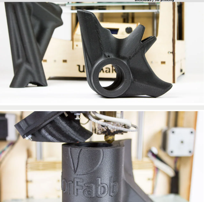
No pictures, but this is how it is done

Drive side, Spider:
-remove crank (imbus 8mm)
-remove the spider (5x imbus 4mm)
-push out rubber oilseal
-push in the bearing (Enduro 6902 LLU-Max) *
-remount spider
-place 14.5mm ID O-ring
-place 15x20x3 mm rubber ring (or second O-ring)
-remount crank
* Sometimes the bearing will be too tight or too loose inside the spider.
Too tight: 15min, heat spider in oven and/or cool bearing in freezer
Too loose: use Loctite 641 or epoxy


Non drive side:
-remove crank (imbus 8mm)
-remove oilseal with a thin screwdriver (axle side)
-push in the bearing (6902 2RS)
-push in the oilseal **
-remount crank
** If the oilseal is damaged with removing, use the spider-side seal.

How it looks on the drive side just before remounting the crank:
bearincomplete.jpg

freexxx said:
HI
problem with wobbling .... outer bearing CSK30P, is it normal ??? by adding 6902 LLU MAX and 6902 2RS I did not solve the problem.....
Because of the tolerances a bit wobbling is normal.
Your video is very short, so I can't see if the wobbling was between inner and outer CSK30P ring or at the axle too.
If this is the case the extra bearings are minimizing this. Did you notice some difference without or with extra bearings?
freexxx said:
,,,,
wobbling is only on outer of CSK30P and axle but only little bit. But orginal BAFANG,BOSCH,YAMAHA,SHIMANO there is a wobbling nowhere.

I haven't noticed an improvement by adding bearings
The tsdz2 is a cheap and easy to service engine, which you can't say about the other brands.
Unfortunately the result is that not all the best parts have been applied.
This and the Chinese tolerances give these sort problems. It is possible to improve this all, by replacing all bearings for premium parts. And narrowing tolerances by the use of shims and glue.
This way you will improve a lot, but for which price and with what advantage. The wobbling will be gone, but the engine will be the same.

imho an addition like the extra bearings, maybe some extra shims are relative cheap and will prevent that the wobbling will be increase. An premium CSK30P like a Stieber will cost a lot, but can solve your problems too.

You are not the first (and last) one that found this behaviour. If you read from here and from there you find some more information about these problems.

Please, don't quote the complete post
 
Last edited:
Moved from here

jmp said:
Hello to all of you and congratulations for this excellent job with this OSF firmware !
I am new in this forum so, maybe, I don't post at the right place, I apologize for that if it is the case.
I have a 8 PIN TSDZ2 controller, (throttle and ebrake functions) an XH18 Display, and I tried to install brake sensors using a splitter 1T2 (6 PIN / 2 PIN), described here :
https://www.aliexpress.com/item/32856818376.html?spm=a2g0s.9042311.0.0.66a14c4dpZbPZZ
The 6 PIN cable is connected to the XH18.
I ordered the Bafang Y Splitter cable and the magnetic brake sensors described in the following link :
https://github.com/OpenSourceEBike/TSDZ2_wiki/wiki/How-to-install-brake-sensors#Magnetic_brake_sensors
I didn't cut the Y splitter cable as described to connect it to the 6 PIN cable, but I just connected it to the 2 PIN cable of the 1T2 splitter.
But the brake sensors don't seem to be detected, and the cruise assist doesn't work. Can you tell me if it is possible to make it working ?
Many thanks for your help.
I have tried to understand what you want, but for what I see is that you want to use a throttle cable for a brake cable.
Imho with the 2pin connection, gnd in that case is missing.
Throttle is +5V and throttle input and the brake is a gnd and brake input.
I haven't experience with these connections, but this is what I think could be the problem.
 
Waynemarlow said:
What you are saying is fairly significant in the " overheating " debate we sometimes see here on the thread. Can you elaborate please exactly what firmware version you are using and what mods did you do to dissipate the heat. Thanks

Firmware version is what was pre-loaded by eco-cycles when I bought. Startup screen says "860C firmware version 1.0.0" I don't know if this is just the display version or the motor firmware version as well.

The intital mods I did were guided by the wiki https://github.com/OpenSourceEBike/TSDZ2_wiki/wiki/How-to-improve-motor-heat-dissipation but making some use of metal and heat-paste instead of thermopads.
Referring to the wiki:
- 'step 2': adding heat-paste to the interface between the flanges and the stator
- 'step 3': instead of using thermopad between the gearbox housing and the motor flange I used copper sheet (beaten flat from pipe) with heat-paste to aid heat transfer and dots of jb-weld to keep the sheet located on the gearbox housing.
- 'step 7': thermopad on the outer stator flange to transfer heat to the cover

But what I think was most significant mod was adding a heat path from the stator body to the cover, along the lines of your post https://endless-sphere.com/forums/viewtopic.php?f=28&t=79788&start=8450#p1649996 but covering the stator body just between the flanges rather than overlying the flanges. Firstly I used JB-weld and heat-paste (jb weld the periphery, heat-paste in the middle) 6 small sheets of 1.2mm (from memory) copper sheet between the bolt holes to provide enough clearance for the bolts. Then JB and heat-paste half circles of 6mm aluminium sheet that I hammered into shape around an appropriate size water pipe. Here's a photo, sorry a bit out of focus:
20201009_143843.jpg

The aluminium ring was an interference with the cover so I then did quite a bit of finessing, putting the stator in place and attempting to put the cover on, using paint pen to find the points of interference and grinding back the aluminium. I think the result was a quite close fit along the full width of the ~200deg of circle that sits near the cover. Then a liberal squeeze of heat-paste on the inside of the cover before fitting:
20201010_150744.jpg

With all this done the motor was still hitting high temperatures and powering back, but now the cover was getting very hot compared to barely warm beforehand. So final operation was to JB weld 10mm high heatsinks to basically everywhere I could:
20210607_183709.jpg

I've finished all this recently and I'm mindful that ambient temp is usually around 10degC here at the moment so will expect to see motor temps go up when the weather is warmer. Even then, if I can still be pushing around 600W constantly then I'll be happy enough.
 
Back
Top