New "TSDZ2 Torque Sensor Central Motor"

Wineglass firstly well done but how do you constantly push 600w ? The most I can do on the flat is about 450w at around 40km/hr and that’s only for a short time since I normally ride at around 30km/hr
 
jbalat said:
Wineglass firstly well done but how do you constantly push 600w ? The most I can do on the flat is about 450w at around 40km/hr and that’s only for a short time since I normally ride at around 30km/hr
If you're referring to the heat dissipation, I think _if_ I've managed to get better dissipation than others have seen it's because there's a heat path with very few interfaces (stator -> thin copper plate -> thick aluminium plate -> cover) and particularly because the way I angle-ground the aluminium ring to be a quite close fit to the cover means there's quite good thermal coupling and not too much thickness of goop impeding the heat flow. Also as I said above, there's quite a bit of heatsinking on the case because before that I was seeing the case get quite hot so the heat was making its way to the case but wasn't shedding that to ambient with the limited area of the case.
I don't think I'm the first to be achieving this kind of power capability, e.g. https://endless-sphere.com/forums/viewtopic.php?f=28&t=102046&start=175#p1655947
 
Wineglass said:
....I think _if_ I've managed to get better dissipation than others have seen it's because there's a heat path with very few interfaces (stator -> thin copper plate -> thick aluminium plate -> cover) .....
Thanks, I refered to the description of your temperature modification in the temperature control topic
 
Elinx said:
I have tried to understand what you want, but for what I see is that you want to use a throttle cable for a brake cable.
Imho with the 2pin connection, gnd in that case is missing.
Throttle is +5V and throttle input and the brake is a gnd and brake input.
I haven't experience with these connections, but this is what I think could be the problem.
Many thanks for this answer, it helped me to see that I made a mistake and I am going to clarify.
The 1T2 cable is not a splitter from 8 PINS to 6 PINS + 2 PINS but to 6 PINS (LCD) + 3 PINS.
The Bafang Y Splitter cable is a 3 PIN cable but I probably didn't connect the 3 PINS correctly as there was a notch and I had to break it because the 1T2 cable didn't have the slot to fit in. So I assume that I should try to identify the right pins and that my previous wiring was wrong.
I measured the voltage at the 3 pins coming from the controller and, if I name them 1, 2 and 3, connecting the "+" cable of my voltmeter on pin number 2, I measured 4.3V volts with pin 1 and 3.2V with pin 3, and nearly no voltage between 1 and 3 (0.1V).
Regarding the 3 pins of the magnetic sensors, only 2 of them seems to be used. I will name them 5 and 6. they are connected when the magnet is close to the cable and disconnected when it is far.
I connected pins 5 and 6 of the sensor cable to pins 1 and 3 of the controller cable.
But I don't see any visible change.
Is it an easy mean to know if the wiring is correct, checking any of the menus on the XH18 ?
 
jmp said:
....
Is it an easy mean to know if the wiring is correct, checking any of the menus on the XH18 ?
imho the brakesensors working outside XH18, so this is not from importance.
The brakesensor is normally an open connection and when pull the brake the input wil shorted to GND.
Only way to check is if the motor rotates or not. If the connection is swapped the motor will not run.
 
Elinx said:
....
The brakesensor is normally an open connection and when pull the brake the input wil shorted to GND.
Only way to check is if the motor rotates or not. If the connection is swapped the motor will not run.
Thanks again for your answer. I will do a few tests. But if anyone has the wiring description of the 3 pins of the 1T2 cable it will help, because, as I described, I measured the voltage and I have 4.3V volts between pins 2 and 1, and 3.2V between pins 2 and 3, and nearly no voltage between 1 and 3 (0.1V). So I tried to connect 1 and 3, but I hesitate for the 2 other combinations as it seems it will bring to the GND a non-zero voltage...
Moreover if the brake sensor is normally open when you don't use the brakes, how does the firmware makes the difference between a brake sensor not closed and no brake sensor connected ? Because my aim is actually to enable the cruise assist mode...
 
Have now tried TSDZ2 V2 for about 200 km and Eco, Tour, Speed, Turbo and I notice a difference.
Now to what I'm not happy about.
I get engine power up to 22 km/h and then nothing at all.
Seems like the maximum speed is set to 22 km/h when it should be 25 km/h.
Anyone can explain this?
 
jmp said:
Thanks again for your answer. I will do a few tests. But if anyone has the wiring description of the 3 pins of the 1T2 cable it will help, because, as I described, I measured the voltage and I have 4.3V volts between pins 2 and 1, and 3.2V between pins 2 and 3, and nearly no voltage between 1 and 3 (0.1V). So I tried to connect 1 and 3, but I hesitate for the 2 other combinations as it seems it will bring to the GND a non-zero voltage...
Moreover if the brake sensor is normally open when you don't use the brakes, how does the firmware makes the difference between a brake sensor not closed and no brake sensor connected ? Because my aim is actually to enable the cruise assist mode...

In my understanding, and as mentioned before, usually the 8pin 1t2 cable is for the display and a throttle, not for a brake sensor. You can see the description for different wires here, but in the 8pin connector table there is a mistake, as the brake wire is not used with the throttle (I tried to correct this a long time ago but for some reason I couldn't edit the page).

You may find the proper wire from the 6 wire cable going to the display, but you need to solder that and a ground wire to a connector or directly to the brake sensor.
 
good evening

hopefully someone can help before i buy a new display.

i recently decided to give open source firmware a go on my tsdz2 however i have had problems flashing my 850c display. i have all the cables from eco cycles the problem is it flashes says its successful but will not power on. i cant seem to find a copy of the stock firmware for the 850c to flash back to stock i did however find maxicolour850c firmware so i flashed that and the display turns on, i have tried osf display refuses to work.

is there any thing i can try before i purchases a new display

thanks in advance Jake
 
The displays are expensive and there are reports of suddenly fail /damage, and then you can not repair them.

You can go wireless and use your mobile phone instead or alternatively use a cycling GPS as a display, like the Garmin Edge. You just need to use our cheap OpenSource EBike wireless controller: https://opensourceebike.github.io/

3d_printed_box.png


3d_printed_box-2.png
 
Dudarus1 said:
good evening

hopefully someone can help before i buy a new display.

i recently decided to give open source firmware a go on my tsdz2 however i have had problems flashing my 850c display. i have all the cables from eco cycles the problem is it flashes says its successful but will not power on. i cant seem to find a copy of the stock firmware for the 850c to flash back to stock i did however find maxicolour850c firmware so i flashed that and the display turns on, i have tried osf display refuses to work.

is there any thing i can try before i purchases a new display

thanks in advance Jake

There is a newer version of the 850c display that I am only aware of one of the TSDZ2 versions working on

https://github.com/emmebrusa/TSDZ2-Smart-EBike-860C/releases/download/v20.1C.3-860C/850C_2021_v20.1C.2-bootloader.bin

Of course the motor needs the matching firmware too! https://github.com/emmebrusa/TSDZ2-Smart-EBike-860C/releases/tag/v20.1C.3-860C
 
ilu said:
...
You may find the proper wire from the 6 wire cable going to the display, but you need to solder that and a ground wire to a connector or directly to the brake sensor.
Indeed your help is really precious, Thanks a lot to both of you !
It helps me to find my mistakes and to make huge progress...
First of all I want to correct what I wrote regarding the 2 useful wires coming from the brake sensors. The exact behaviour is :
they are disconnected when the magnet is close to the cable (open) and connected when it is far (shorted). So it is as Elinx described.
I followed your advice regarding using the 6 PIN wiring and I connected one pin to the GND and the second one to the purple brake pin. And it works... The motor stops when I pull the the brakes on.
So my last step is to activate the cruise assist mode. With my XH18 display, how do I activate this mode, to keep the motor running when I stop pedaling ?
 
I’m using firmware 20.1c using a VLCD6 display 48v. I thought by default the 2 figures are soc% and volts this is what I got. ( I’m copy and pasting a note I did during ride )


If I turn lights on I get readings. It displayed this first 99.9-88.9
After 1 mile it dropped down a bar to 3 bars!after 11miles 2 bars remained.
At 18 miles says 82.9 / 79.4 Still 2 bars
23 miles 1 bar(flashing to 2 briefly) 57.4 / 77.8
25 miles 1 bar with odd flicker to 2 47.8/76.2
33 miles 12.9/71.8 1 bar
Rode about 1 mile more to display 10.4/74.6 It then powered off and managed to briefly turn on to display 7.1/71.8

What do these number mean
 
Huguenot said:
Greetings all.
My wife's cargo trike is still at OSF 6.3. It's buggy, but we have learned to live with it. Usually works fine, sometimes we have to restart 5-6 times to avoid a whine/growl. Once we get it running quietly it will behave all day.
Recently it has added the annoying habit of the odometer resetting to 188.1 miles. It had been over 500 before. The trip meter works, and the odo increases in step with it, but when we power off and on again the trip resets like it should but the odo always returns to 188.1.
Anyone have any ideas?
Yes, I know -it's past time to upgrade to 1.0/1.1. I have the cables but no PC (we are Mac based) and am way more of a machinist/fabricator than a software guy anyway.
Is there someone the Palo Alto-San Jose California area willing to upgrade this thing for me? Beer, cash, machine work, whatever.
Thanks -Paul

You need to upgrade the firmware. 0.6.5 had similar issues, the motor would fail to init properly once in a while and make a horrible noise. Had to restart it several times before it went away.

This has been resolved in later firmware versions, so you'll need to bite the bullet and upgrade. On a Mac, you can run a Windows VM (the 8x0C display update software only runs on Windows AFAIK) to upgrade. In my opinion, the hardest part to update motor and display is building the cable, but if you already have the cable then you're good to go.
 
BunnyMan69 said:
20.1c using a VLCD6 ...I thought by default the 2 figures are soc% and volts ...
......
If I turn lights on I get readings. It displayed this first 99.9-88.9.....
...
What do these number mean
Default settings:
If your battery is above 54V the soc% will be reset to 99.9%, display first reading should be about 99.9/54.1
all bars 54V (4 bars)
one bar drop at 51V (3 bars) .... (you have to see, on display, something like this: ~86.9/51.3)
two bar drop at 48V (2 bars) ..... (~57.4/48.1)
three bar drop at 45V (1 bar) .... (~12.9/45.2)
flashing bar at 41V .....(~10.4/41.0)

First:
It looks that your first reading is indeed soc%, but the second reading is NOT Voltage (advanced settings 2)
Check this with your last ini file in the configurator (could it be temperature Fahrenheit? advanced settings 0)

But .........

edit:

Second:
It could be something with the unit (mile) calculation settings, because if I calculate the 4 bars 88.9/1.61= 55,2 and 1bar 71.8/1.61= 44.6, it looks more like (a bit high) battery Voltage
You must setup mph inside configurator AND display.
Please check this too in your last ini file in the configurator and display settings.
 
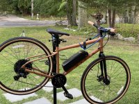
just wrapping up another conversion on a marin hybrid

A6422D42-8CE8-4F87-A9FA-3FFB859D9DF3.jpeg

just have to finish up the rear cable routing and a few other touches

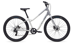
and another due next week for a customer using this bike


B8DD3483-5F56-4A5C-959E-5901A1F4DD8B.png

having really good luck with the marins, the internal routing makes for a super clean setup and they have pretty good stock on a lot of them at citygrounds a a few other retailers
 
Hey Guy's,

my TSDZ stopped working after the last maintainance, meaning that the assist is gone. All other functions remain working, including walk assist.
I checked the technical readings and i get signals vor weight and torque but not for PAS, also the indication for the upper/lower pedal isn't changing.

Does some one know what might cause this error, i guess it might be a faulty PAS sensor ?
Where is the PAS-sensor in this kit and how does it work ?
 
Thank's for the fast reply :bigthumb:

I already read it but i wasn't sure if there might be another point that i'm missing, because the sensor stopped working right after the maintainance.
The thing is that i'm a little confused, how the sensor can be sanded if the torque ring on the inside doesn't turn ?

Well anyway i guess i might need to dissasemble it again to check the sensor and/or the ring.

In case i need to order a new controller, are there any differences between them beside the voltage and the number of pin's ?
I've seen some offers which were just labeld with the voltage but without the power output.
 
Heisenberg60 said:
.....order a new controller, are there any differences between them beside the voltage and the number of pin's ?
I've seen some offers which were just labeld with the voltage but without the power output.
Every controller is exactly the same. As you said number of pin's could be different
They are labeled with 36V or 48V, because of the two motor versions.
If you flash OSF, the Voltage choice is to you inside the settings.

But if you buy another controller and you want to flash it with OSF.
Don't do this at Enerprof.de, because they sell only the new 2020 controller version, which you can't flash.
Choose an other International seller.
 
Manbeer said:
just wrapping up another conversion on a marin hybrid

having really good luck with the marins, the internal routing makes for a super clean setup and they have pretty good stock on a lot of them at citygrounds a a few other retailers

Looks very neat. I have a Kona with internal routing, but how did you thread the cables through? I'm guessing you have to cut the plugs off and resolder on the other end, but the cables themselves are much thicker than the gear shift cable that originally went in the hole. Did you get custom plastic covers with a larger diameter?

About the cables, would also be curious to see more pics re connecting the battery to the motor. Mine came with rather long bullet connectors which makes an approx 3" stretch that is rigit and won't bent... So I kinda wrapped that around the seat post but it looks very ghetto. Same issue with the connection from the wire loom between the display and the motor or motor and speed sensor. Basically, would love to see more detailed pics at the cables arrangement if you don't mind :)
 
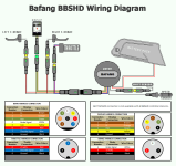
Maybe this will help?

BBS_Wiring_Diagram.png


jmp said:
Elinx said:
I have tried to understand what you want, but for what I see is that you want to use a throttle cable for a brake cable.
Imho with the 2pin connection, gnd in that case is missing.
Throttle is +5V and throttle input and the brake is a gnd and brake input.
I haven't experience with these connections, but this is what I think could be the problem.
Many thanks for this answer, it helped me to see that I made a mistake and I am going to clarify.
The 1T2 cable is not a splitter from 8 PINS to 6 PINS + 2 PINS but to 6 PINS (LCD) + 3 PINS.
The Bafang Y Splitter cable is a 3 PIN cable but I probably didn't connect the 3 PINS correctly as there was a notch and I had to break it because the 1T2 cable didn't have the slot to fit in. So I assume that I should try to identify the right pins and that my previous wiring was wrong.
I measured the voltage at the 3 pins coming from the controller and, if I name them 1, 2 and 3, connecting the "+" cable of my voltmeter on pin number 2, I measured 4.3V volts with pin 1 and 3.2V with pin 3, and nearly no voltage between 1 and 3 (0.1V).
Regarding the 3 pins of the magnetic sensors, only 2 of them seems to be used. I will name them 5 and 6. they are connected when the magnet is close to the cable and disconnected when it is far.
I connected pins 5 and 6 of the sensor cable to pins 1 and 3 of the controller cable.
But I don't see any visible change.
Is it an easy mean to know if the wiring is correct, checking any of the menus on the XH18 ?
 
Hello to all TSDZ2 fans.
1. I changed the display to Bafang 860c, I uploaded the software to the display (1.1.0) and engine (1.1.1), everything works fine except for one thing. I have a temperature sensor installed in the engine and when it activates in the options in the 860c, it shows the correct temperature, but interestingly, the engine does not support. The temperature is not exceeded in terms of the temperature range. What could be the reason? Everything worked on the old KT LCD3, so I conclude that something needs to be changed in the 860c settings.

Ad 1. solution: poor connection between sensor and controller

2. I performed the pressure sensor measurements according to the available guide on the OS project website for TSDZ2. In the 860c settings, I set the calibration to "on" and set the ADC values ​​and weight according to the thin lines plotted on the graphs below. But why after calibration, when I put, for example, 10 kg on the pedal, I still read the value from before the calibration, and not the new one that I set? Is this the correct symptom or am I doing something wrong?
ADC.jpg

Thanks for any suggestions.
 
VLCD5
What do the numbers 6-35 mean during Power Setting (A)?
Why not 1-30 instead of 6-35?
 
Back
Top