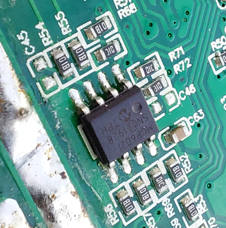
So, there are 3 dual opamps. 2 of them are the MCP6022 and one of them is the LM258. This gives a total of 6 opamps available.
I just checked the MCP6022 near the shunt resistor and I found:
1. one opamp is in the no inverting configuration with the gain of 11, measuring the shunt resistor (can only measure positive current values, just like on the V1 hardware).
2. other opamp is in the inverting configuration with the gain of -10, measuring also the shunt resistor, but has also an offset of 2.5 volts, meaning it can measure both positive and negative values.
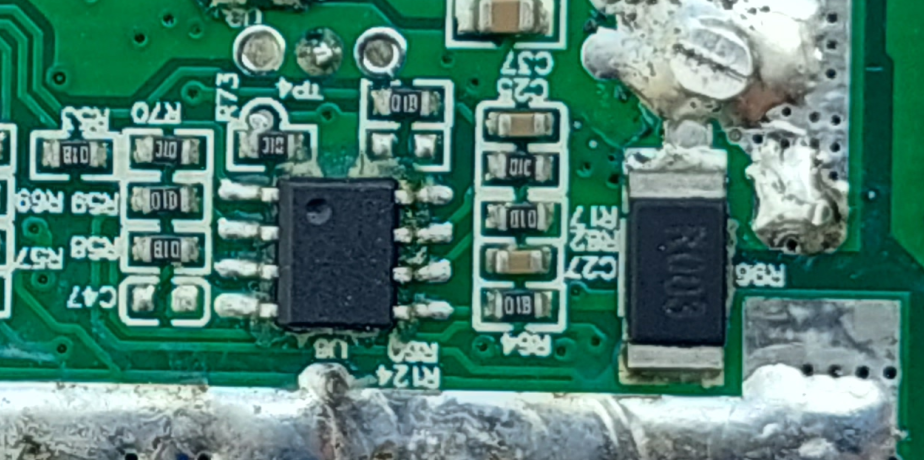
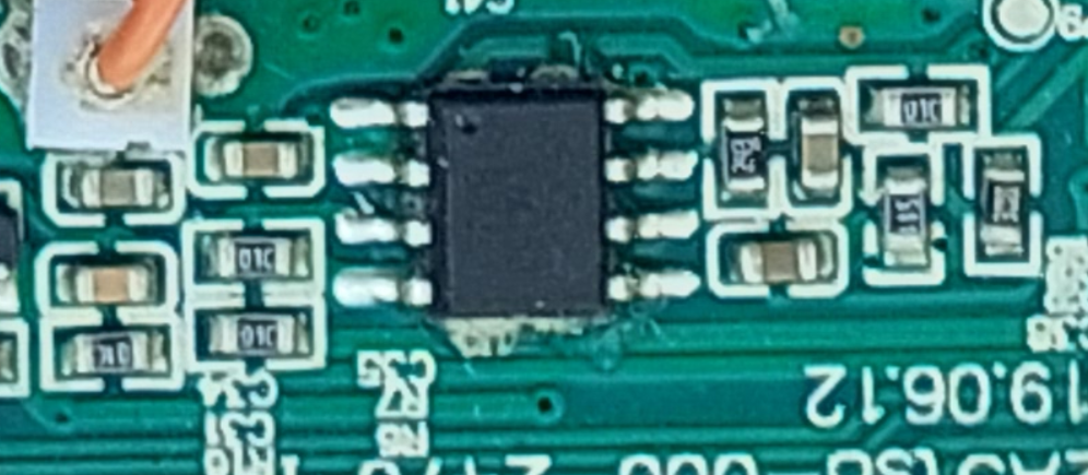
What is strange is that I can see the other MCP6022 with gain of -10 and 2.5V offset, for sure measuring the 2 of 3 phase current resistor voltage. BUT, I also see the LM256 with gain of -10 and 2.5V offset, measuring the other 1 of 3 phase current resistor voltage.
So, why would they use two MCP6022 and a LM256 to do the same function, while they could use instead the same MCP6022 or the same LM256??
Here a picture of the circuit:
Akita said:
Can't find your Paypal.
What's the name?
It is on my signature.


")