Hardware temperature control tsdz2

Hi, I'd like to share my own experience with thermal dissipation.

I first did the mods with thermal pads and grease as indicated in the wiki.
I also added 20x30x2mm thermal pads against the motor laminations, between the flanges screws, and top of that, 3mm thermal pads wraped around the motor to make contact with the case.
I bought the thermal pads for cheap on Aliexpress, rated for 6 W/mK, but who knows what their real conductivity is..

It was better that before, obviously, but I still could reach 70°C (the min temp warning limit I've set) quickly when drawing 500+W continuously from the battery.

Then I decided to put as much aluminium as I could instead, like others have previously done.

I had 1.5mm and 2mm aluminium sheets laying around, so I first cut a 1.5mm shim to go under the motor (first described by a smart guy earlier in this thread), with thermal grease on both sides of the shim. I used a jigsaw and a file to make it, so it's not as pretty as a CNC machined one, but it was easy and did the job.
For the wraps around the motor, the use of an aluminium tube as described just earlier here would be the best, but I'm tight and lazy and wanted to use what I already had : that 2mm aluminium sheet.
So with the jigsaw I cut a 2cm wide band, and curved it around an empty spray can which happened to be approximately the same diameter as the motor. I cut it in 3cm long pieces and glued them with thermal compound against the motor laminations, between the screws.
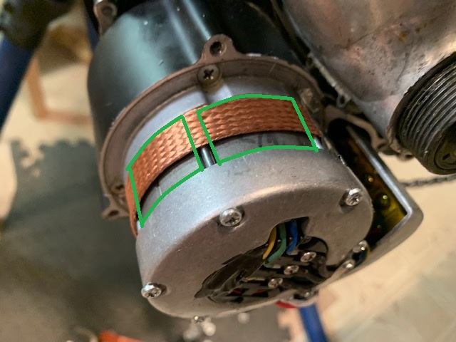
Then I did the same with a larger band (can't remember the exact size, 3cm something). This width is already more difficult to work with when you don't have a proper roll bender machine, so I used two clamps around the empty spray can in order to bend it to the correct shape. Then I cut it into 3 pieces (I had to use a new band each time : only the center of the curve had the good radius and there are wastes..) and glued them around the motor, between the motor fixing screw hole.
It looks like this :
IMG_1979.JPG

The advantage of this method is that even with the aluminium shims permanently attached to the motor, the mounting screws are still accessible and allow the motor to be easily removed and reinstalled for maintainance. Everything stays in place.
Yet, 2mm is not enough (3mm would be ideal) so I stuck 1mm thermal pads on theses curved shims, with thermal grease on top for good measure.

Now the good news : with this mod and the latest 20.1C3 firmware from Mbrusa (based on Mspider65 v13, which brings enhancements regarding heating and other things), I simply haven't managed to reach the low temp warning !
On my 'test hill' before (with thermal pads mod and 20.1C2), I would hit 70°C before the top when drawing 500 to 700W continuously. Now I'm just above 60°C at the top of the hill with full power all along.
Please not that I ride on the road with this bike, so with high power I go fast even uphill, so there's lots of airflow around the motor case, helping it cooling down. In a MTB situation with slower speed and high power uphill, it's probably possible to overheat the motor, but this would happen much later.
Also the temperature here theses days is 15-20°C. It will be different this summer with 30+°C, but I'm really happy with how this thing works now.

In conclusion :
Thick cheap thermal pads suck. Aluminium rocks.
Mspider65 and Mbrusa absolutely rock.

Edit : For the sake of completeness, I use a 48V motor with a 14S battery, with a 750W/16A limit (I was drawing probably 12 to 14A for the test reported above). I pedal at a maximum cadence around 80-85, with field weakening enabled.
 
Wineglass said:
.... After extensive thermal improvements guided by the wiki (thanks to all involved) I can get 750-800W constant output with steady state temperature of about 70degC.....

Wineglass made his motor more heat resistant.
He has packed the motor complete with mixed materials and heatsinks on the motorcase.

"The intital mods I did were guided by the wiki https://github.com/OpenSourceEBike/TSDZ ... issipation but making some use of metal and heat-paste instead of thermopads.
Referring to the wiki:
- 'step 2': adding heat-paste to the interface between the flanges and the stator
- 'step 3': instead of using thermopad between the gearbox housing and the motor flange I used copper sheet (beaten flat from pipe) with heat-paste to aid heat transfer and dots of jb-weld to keep the sheet located on the gearbox housing.
- 'step 7': thermopad on the outer stator flange to transfer heat to the cover

But what I think was most significant mod was adding a heat path from the stator body to the cover,.............
"

file.php


nb
"I think _if_ I've managed to get better dissipation than others have seen it's because there's a heat path with very few interfaces (stator -> thin copper plate -> thick aluminium plate -> cover) and particularly because the way I angle-ground the aluminium ring to be a quite close fit to the cover means there's quite good thermal coupling and not too much thickness of goop impeding the heat flow ......"


The complete description of Wineglass you can find here:
https://endless-sphere.com/forums/viewtopic.php?f=28&t=79788&start=8700#p1660215

.
 
Thinking about this a little and seeing that others here have tried water cooling solutions, how about something like this:

Option 1. Fabricate a couple of 3/16" copper tube sheets with a few back and forth bends and overall bent to the motor curvature. Make 2 of these to fit on the top and bottom where there is more room in the case. Connect the 2 in series, clamp to the motor case with a zip tie then drill a couple holes in the top of the case cover to stub out the inlet and outlet. Then use a 5v PC cooler pump that can tap power from the motor... could even be switched from the handlebars. Use a 80mm radiator but ditch the PC cooler radiator fans, these should not be needed. This is a very rough drawing just to illustrate the concept. Whilst I certainly can solder copper I don't think I have the fab skills to make anything this precise and delicate.... but someone here might?

TSDZ2 cooler.JPG


Option 2. Use the same PC cooler and radiator but instead of copper use about 5 wraps of 3/16" silicone tubing around the motor. Stub that out the top as before and connect to the pump and radiator. Certainly the silicone wouldn't be as conductive as the copper to transfer the heat to the water. But maybe good enough?

These TSDZ2 bikes ride so well on the OSF it is a shame that the cooling issue becomes so limiting.
 
raylo32 said:
...water cooling solutions, ..
Option 1. Fabricate a couple of 3/16" copper tube sheets ..
..
Option 2. Use the same PC cooler and radiator but instead of copper use about 5 wraps of 3/16" silicone tubing around the motor. ..
An active closed watercooling circuit :)
imho Option 2 is the most flexible solution to insert inside the motorhousing, but has ~5mm silicone tube enough cooling capacity?

What about option 1B: Wrap copper tube around the motor? Should that be more effective as silicone tube?
It isn't that flexible so there could be a problem with fitting the case cover.
 
Copper certainly would be better but making the curvature to keep it tight to the motor might be difficult to do and to not pinch the copper? Again, thinking about my fab skills. Others may be better. And I wonder about clearance in the tight spots to get the cover on. OTOH with silicone the tubes could get pinched and impede or stop water flow.

Elinx said:
raylo32 said:
...water cooling solutions, ..

What about option 1B: Wrap copper tube around the motor? Should that be more effective as silicone tube?
 
raylo32 said:
Thinking about a PC cooler like this:....
I'm not a expert, but active cooling with an peltier element/cooler and/or air radiator could help too.
But as said. I know nothing about calculations for that.
 
That cooler has an air radiator... just covered by the RGB fan that would get removed. The bike's motion should provide enough airflow... and heat isn't an issue when stopped like for an idling ICE.

The radiator certainly would help, but would it be enough? The devil is in the fabrication/fitment and thermodynamic details. Have to try it in the real world and see. Perhaps a 3D printed cover could be designed to add some needed clearance in the tight spots? I'll have to look into that, too but my CAD skills are intermediate at best.

Elinx said:
raylo32 said:
Thinking about a PC cooler like this:....
I'm not a expert, but active cooling with an peltier element/cooler and/or air radiator could help too.
But as said. I know nothing about calculations for that.
 
Those are interesting but for a bike application the main issue is power consumption. I am seeing 100+ watts for peltiers which would be highly detrimental to range... and require a fairly high power source from the motor. Not sure there is a place to tap that directly without more work. The passive air radiator setup only needs a tiny bit of 5V power for the pump that is readily available on the same wires used for the temp sensor so that would be the first thing to try IMO.

Elinx said:
raylo32 said:
That cooler has an air radiator... .
That is why I mentioned a peltier cooler.
That depends not only from airflow for cooling the motor.
 
raylo32 said:
Those are interesting but for a bike application the main issue is power consumption. I am seeing 100+ watts for peltiers ...
As said. The usual solutions with passive cooling do work too, so you need some calculation for active peltier or air radiaton closed watercooling. I only mention and link these adhoc, maybe you don't need 100W plus.

An advantage is that the radiator is on the outside of the motor, so it can be easily exchanged.
I think the biggest challenge is fitting the tubes within the Tsdz2 cover and keep the Tsdz2 service friendly
 
I'm curious to hear what kind of temperatures you guys are getting with thermal pads between outside motor end and case and a heatsink plate as they seem to work well enough in my experience that I don't see a need for any extreme measures like water cooling. After all, we can't crank up the power past the 52v 20A most of us are probably already set to. Be curious to hear the difference in warmer climates though.

If extreme cooling was your goal though I would say heat pipes would be the good option, you can get bare pipes or pipes with heatsinks already attached cheaply and then they could be mounted to the motor and exit via a port placed next to the cover seal, matching a slot cut into the motor cover so you could remove the cover without disturbing the pipes. A reasonable amount of them would provide a similar cooling to water cooling (as many air vs water cooling PC test videos will demonstrate) without pumps, hoses, radiators, risk of leaks, complex custom water jackets, etc.
 
I just did my first real ride with the 850C and temp sensor. I had done a couple of rides with the VLCD5 and temp sensor and saw 63 or so, but that was just snapshot what with having to press the button to get it so it is likely that I missed higher readings. With the continuous display on the 850C I see I have a problem. I did 22 miles here in our rolling hills on this beautiful cool (for here now) 75 degree F day and the motor started at 21C, my basement room temp, and lived above 70C with any effort at all. Longer hills it hit 80. I was riding mostly in level 3 or 4 and not really going much above 300 watts motor power except intermittently. Even on flats with extended pedaling it would easily approach 70. I had to soft pedal a lot and turn the boost off completely on longer downhills to get some cooling. I have actually done the same ride with faster average speed on my all human pedal road bike.

I guess I need to spend more time on this thread and see if I can duplicate a method that might help. Otherwise this bike will be relegated to the occasional lame coffee shop run.
 
And I have yet another idea, trying to come up with something easier than trying to shape hard pieces of alu or copper to fit under the case. How about metal BBs, poured into a piece of MTB innertube with the ends sealed. Then wrapped around the motor and held on with a zip tie. Thinking that if filled and fitted correctly this might be squishy enough to form fit into the gap as the cover is installed. Maybe another small bag on the ends. I ordered some BBs and might give this a try next week. Yes, I know the rubber will be somewhat insulative but with pressure and decent contact it might be transmissive enough. And the sub 100C temps we are talking about won't be enough to melt the rubber.
 
raylo32 said:
How about metal BBs, poured into a piece of MTB innertube with the ends sealed. .... Yes, I know the rubber will be somewhat insulative ...
The thermal conductivity of rubber is about 0,15 W/mk, so that is more than air (0,02 W/mk) but less than the cheap sticky silicon thermal pads (2 á 6 W/mk).
The metal BBs are between 2 layers of rubber, so I can't predict what the influence will be on the motor cooling.

FYI:
Copper 380W/mk, Aluminium 205W/mk, Steel 50W/mk, iron 80w/mk
So you understand the experiments with copper and aluminium
 
I can't predict it either. But the rubber will be very thin and if the fit is tight there should be some decent conductivity. The devil will be in the execution.


Elinx said:
raylo32 said:
How about metal BBs, poured into a piece of MTB innertube with the ends sealed. .... Yes, I know the rubber will be somewhat insulative ...
The thermal conductivity of rubber is about 0,15 W/mk, so that is more than air (0,02 W/mk) but less than the cheap sticky silicon thermal pads (2 á 6 W/mk).
The metal BBs are between 2 layers of rubber, so I can't predict what the influence will be on the motor cooling.

FYI:
Copper 380W/mk, Aluminium 205W/mk, Steel 50W/mk, iron 80w/mk
So you understand the experiments with copper and aluminium
 
And here is another thought... Substitute metal mesh for the innertube, If I can figure out a way to make a sleeve out of this:

https://www.amazon.com/gp/product/B08NP8WGKZ/ref=ppx_yo_dt_b_asin_title_o00_s00?ie=UTF8&psc=1
 
I am liking that idea. That steel wire conduit sleeve... or similar copper I found at Digikey... (https://www.digikey.com/en/products/detail/techflex/MBC0.38CP25/5215829) might even be used all by itself. Just put a wrap or 2 around the motor, whatever it takes to fill the gap and compress against the cover.

Elinx said:
raylo32 said:
...metal mesh..., If I can figure out a way to make a sleeve....
...
It is possible to buy steel or copper sleeve too.
Silentguy has used this earlier and Thousendwax has mentioned the idea there, before this topic started.
 
I don't have my copper mesh yet but I already had some 1/8" (~ 3mm) silicone sheet from another project so I decided to try that for now. See the pic below for the spec. I tested its ability to transfer heat by warming a cast iron pan to about 185F then slapping the big silicone sheet on it and taking the surface temp with an IR thermometer. The surface warmed about 30 degrees F in 30 seconds, which I thought was pretty darn good. Not up to what copper would do but perhaps good enough??

So I cut a thin strip to snug down in the central motor channel and another wide strip to cover the entire motor on the non-drive side. There was a pinch point in the case about 2 o'clock so I cut about 5mm section out of the wider strip there (not shown). No thermal paste or adhesive used. Case was a very snug fit so I applied a little sil-glyde to help get it on.

So to the results... I didn't follow a rigorous scientific procedure but the results were clearly positive. I rode the same route I took the other day including one 2 mile section that is an overall climb with just a couple of small downhill dips. The other day I used low assist and kept power in the 200-300W range and hit 185F. Today I started easy but found that temp was better controlled so quickly ramped it up to full power... and the highest I was able to hit was 165 at the end of the climb with motor power showing 600-700 watts after doing the bulk of the climb in the 400W ballpark. More evidence that the cooling is improved... the temp sensor reading reverses much faster when I get off the gas than without the mods which shows that the motor is cooling better. Don't get me wrong. I don't believe that my mods so far would support steady state at 700+ watts. But I really don't plan or need to push it that hard.

IMO, these hardware mods (along with OSF, of course!) are a game changer for the TSDZ2. I may pursue this further but honestly I am not sure I need to.


silicone.jpg

IMG_2713.jpg

IMG_2714.jpg
 
Continuing with my personal experiments...I bought this from Amazon: https://www.amazon.com/dp/B01F47W86C?psc=1&ref=ppx_yo2_dt_b_product_details. This stuff is pretty dense but just a very little compressible and about 1.5mm thick.

Then cut it in strips just long enough to wrap the motor and terminate at the controller. Taped the ends to keep pieces of wire from potentially going adrift and getting into the electronics. Then wrapped the motor center with one full piece and one that was ripped in half, then 2 more full wraps of the entire motor, taping the layers down with HVAC metal tape. I ended up using almost all of the 5' roll.

Tested on the same route as above, pushing the power even higher. The max temp reached was 155F (68C), a full 10 degrees F cooler than with the silicone. And the transition to cooling when the power was removed was notably faster as was the temperature drop with time. VERY noticeable. At the end of the ride that includes some downhill the motor was 12 degrees F cooler than the other day with the silicone. And the delta T between the case and motor was 12 degrees F whilst with the silicone it was 33 degrees F.

All in all, a very positive result and a fairly easy install. It would be easier still if we had this sort of material in a mat. I had a small issue with the last wrap bunching up a bit at one spot of the case so it didn't close flush. Not that I ride in the rain but I will open it up again and fix that. I may even try to weave or tape these sleeves together into a mat of sorts to make the whole process easier.

CopperStrips.jpg

CopperWrapFirst.jpg

CopperWrapFinal.jpg
 
raylo32 said:
Continuing with my personal experiments...I bought this from Amazon: https://www.amazon.com/dp/B01F47W86C?psc=1&ref=ppx_yo2_dt_b_product_details. This stuff is pretty dense but just a very little compressible and about 1.5mm thick

Very interesting. Thanks for sharing @raylo32.

Do I understand correctly that you omitted the copper heatsink on the portion facing the controller? In other words, the copper strips do not wrap around the complete circumference, right?
 
Yes, correct. It might have a warm spot where the copper is absent but the heat will still flow from there to where the copper is. I was trying to come up with a quick non destructive install. It was a challenge getting the case on as the copper likes to bunch up a little on the edge where it closes. I have about a 1/8" gap there that I taped over for now. If you can wrap the whole motor and get it snugger this might not be an issue. I may play with it some more again to work the fit... maybe pull the motor off the bike and do it on the bench. But the cooling is really good and plenty enough for my use case. Oh, in the last iteration I included a piece of the thermal pad in the case that butts onto the end of the motor where the phase wires connect. Probably not necessary but why not?

seattlesockey said:
f=ppx_yo2_dt_b_product_details. This stuff is pretty dense but just a very little compressible and about 1.5mm thick

Very interesting. Thanks for sharing @raylo32.

Do I understand correctly that you omitted the copper heatsink on the portion facing the controller? In other words, the copper strips do not wrap around the complete circumference, right?
 
raylo32 said:
Oh, in the last iteration I included a piece of the thermal pad in the case that butts onto the end of the motor where the phase wires connect. Probably not necessary but why not?

How thick are those pads supposed to be for it to contact the outer cover? I've seen some people use 3mm and some use 5mm, not sure what to use!

Also about the copper mesh wraps...wouldn't it be beneficial to put thermal pads in between the screws that hold in the motor (in the green boxes pictured below)? It looks like the screws are slightly raised from the surface which would cause a small air gap when wrapping the copper strips tightly around it.

4KCfzm0.jpg
 
I am not sure exactly how thick the end pads in the case need to be. I am not there to see the package but my pad is thin so I cut about 3 pieces of it. Overall it might be about 4mm thick? When I pull the case off I see the impression from the end of the motor so it is making contact. I'll try to remember to check this next time and give you an accurate report of what I have.

I don't think adding thermal pad where you indicated it necessary. This copper sleeve material is flexible enough that I believe it pushes down on the motor when the case goes on. Or at least good enough.

suppi said:
raylo32 said:
Oh, in the last iteration I included a piece of the thermal pad in the case that butts onto the end of the motor where the phase wires connect. Probably not necessary but why not?

How thick are those pads supposed to be for it to contact the outer cover? I've seen some people use 3mm and some use 5mm, not sure what to use!

Also about the copper mesh wraps...wouldn't it be beneficial to put thermal pads in between the screws that hold in the motor (in the green boxes pictured below)? It looks like the screws are slightly raised from the surface which would cause a small air gap when wrapping the copper strips tightly around it.

4KCfzm0.jpg
 
Back
Top