Instant Start 18 fet Infineon Boards are here...

why not do what knuckles did originally with the infineon transistor modification. first he latched the 12V rail with the 15V zener and then latched the input of the LM317T at 51V with the 36V zener, maybe you could go extreme and use an 18V zener to latch the 12V bus and add a 40V zener on top to peg the VR input to 58V-Vbe. that would work with the 107V Vcc, dropping the 50V with a 1k6R and 1k5R 2W in parallel. about 3.2W total. plus it would run all the way down to LVC on the battery pack then too. my education from knuckles.
 
Time, parts, and labor.
It sounds easy enough until you have 30 controllers sitting in front of you and you make like $20 for the entire build of each... :roll:
Adding that gadget (which is a very cool gadget) becomes un-cool when I now have to work on each board for 10 minutes longer.

After this batch of 30 I want to get Kenny to build these setups. It is hard enough trying to just get a Chinese vendor to run copper wire and one fet vs. another.... Asking them to make a gadget like what Knuckles came up would be difficult. If it was easy than he would have had Keywin doing it for him.

I think the current 12V regulator will work just fine with maybe the addition of a better resistor across the SMT parts.
This will add nearly no cost...

See the trouble is that when people are ready to buy a controller they get cheap and short sighted. If that mod increases the cost of the boards by $10 that is significant since, in my opinion, it does not add all that much value if the regulator works as is.

Trying to make the cheapest 10KW controller possible.
If we optimize each part of the circuit we will get scope-creep and before we know it we will have a Kelley that costs $350

I think SAM-Pilot has a good argument for keeping the regulator as is.

-methods
 
My experience with the 12-fet Infineon tells me that there is a 48V “mentality” when it comes to the “off-the-shelf” voltage regulator design. I worked around this limitation using the “transistor mod” to allow safe operation at 36V or 72V or higher.

The 12-fet uses an LM317 to regulate the 12V bus while the 18-fet uses the comparator circuit. These are two completely different voltage regulator designs.

It’s not just the voltage to consider but also the current in the regulator.

The 12-fet needs a minimum of about 30ma (motor/throttle not connected) and peaks at about 70ma (motor running at about ½ throttle). These values where obtained from direct measurement.

I would guess that the 18-fet pcb would require more current than the 12-fet. Maybe even as high as 100ma.

If we use the 92V bat as an example and we have 27ma from the "base series resistor(s)" the remaining current required passes thru the “primary” transistor and the “switched series resistors”. In the example the “switched series resistors” = 500 ohm.

So passing 10ma thru the 500 ohm creates a V drop of 5V.
Passing 20ma thru the 500 ohm creates a V drop of 10V.
Passing 40ma thru the 500 ohm creates a V drop of 20V.
Passing 60ma thru the 500 ohm creates a V drop of 30V.

But the overall V drop is 92 – 12 = 80V. This means there must some voltage drop across the “primary” transistor. I suspect that the “primary” transistor is really acting as a “variable” resistor as controlled by the secondary transistor and the comparator feedback circuit.

In any event … the “primary” transistor (TO92) might get very hot during 92V operation.

Passing 10ma thru the “primary” transistor creates a V drop of (80-5) = 75V.
W = V x A = 75 x 0.01 = 0.75 Watts

Passing 20ma thru the “primary” transistor creates a V drop of (80-10) = 70V.
W = V x A = 70 x 0.02 = 1.4 Watts

Passing 40ma thru the “primary” transistor creates a V drop of (80-20) = 60V.
W = V x A = 60 x 0.04 = 2.4 Watts

Passing 60ma thru the “primary” transistor creates a V drop of (80-30) = 50V.
W = V x A = 50 x 0.06 = 3 Watts

Also this 18-fet pic from Geoff57 looks different … no circuits to short out on the controller case.
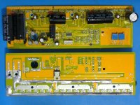
18-fet.jpg

18-fet.jpg
 
Yes, I wholeheartedly support not upgrading many different parts because it's true that multiple 5 to 20 dollar chances can easily become hefty which, in my opinion, would detract from the Infineon's original competitive advantage.
 
Knuckles said:
Also this 18-fet pic from Geoff57 looks different … no circuits to short out on the controller case.

Thanks for the calculations Knuckles.
That board you are showing pictures of is the Slow Start board that everybody hates... the one that cant be programmed.
It is the last of the actual Infineon boards.

The boads in this thread are the Fast Start board - totally redesigned with a different non-Infineon processor, different shunt, different layout, additional features, new programming software, etc. Many bugs are addressed but perhaps a few new bugs were added :D

-methods

Edit: P.S. I still have 3 or 4 of those slow start infineon boards that I will sell at cost. Some are fresh out of the box, some are built half way up with IRFB4110's, and some are completely built. I am done with them. PM to inquire. Perfect for the "normal" ebiker who does not insist on motorcycle performance. Just as powerful but with a $hitty throttle response.
 
So I assembled a board to test the temperature across the base resistors.

Vcc = 100.8V
Icc = 34mA (could have been 36mA, there was loud sparks and fire before I wrote the number down :roll: )

Vbase = 83.3V (across the 3 resistors)

Temperature stabilized at 80C (180F)

That is just fine for government work!
Only question is how hot it gets when the board is under load :?:

Unfortunately before I could test the temperature under load I let the magic smoke out. 8)
Some of you may remember that I was pulling big sparks on the 9C thread with a set of banana jacks, a 100V battery, and a space heater.
For some stupid reason I used that same set of banana jacks to plug my ammeter inline for the second part of the test.
The plugs were so beat up that when bumped they would toggle intermittently, but I did not realize this at first.

Well, as soon as I bumped the cables the power went ON-OFF-ON-OFF-ON-OFF really fast and I blew major flames out of C2.

No big deal... I have a respectable bone yard. I will scavenge one and try again.

It appears that the system still idles fine without C2.

-methods

EDIT: Replaced C2, all else seems fine. I need to check the temperature specification on those resistors. Either way I think 180F is fine and nowhere near the de-solder temperature.
 
Methods,

The temp will rise alot when the board will be inside the case !. (the ambiant temp inside will rise as well). Can you just put it inside for the test?
 
That's a good idea doc.
I will do that.

I already agree that we should replace the SMT's with a leaded resistor but I still want to know... you know?
I like to know what we can get away with.

I will leave my personal controllers with the SMT's and see if I get any failures. I can instrument them and capture the peak temperature.

-methods
 
Methods, here is the step by step instruction to properly install the program on the English version Windows XP operating system (It has also been tested on Vista 64 bit OS):

1. Go to Start > Control Panel > Regional and Language Options > Languages tab and click on "Install files for East Asian Languages" & apply
regionalandlanguageopti.png

2. Install the Microsoft AppLocale Utility from here > http://www.microsoft.com/globaldev/tools/apploc.mspx
3. Download the program from here > http://www.xie-chang.cn/administrator/upload/2009328122310362.rar
4. Using Winrar, extract the program like this & be sure you see exactly the files with the Chinese named files below:
extracthere1.png

extracthere2.png

5. Run AppLocale > Next > Launch an application > Browse > setup.exe > choose Simplified Chinese > Finish
6. You should see a Dialog window like this & click on the lower left button for installation confirmation below:
installdialog1.png

7. Click on the icon for the default installation path below:
installdialog2.png

8. Click on the lower left button to continue below:
installdialog3.png

9. Now this part is a little tricky. It prompts you if you want to over write the Windows Common Controls ActiveX Control DLL with an older version. Make sure you choose the middle button for NO although the older version may works but try not to screw up your OS whenever possible. See below:
installdialog4.png

10. The dialog window below tells you the "Dual machine connection program" installation is complete
installdialog5.png

11. To run the program, execute the MS AppLocale application again and choose the path below:
runprogram1.png

12. Select an executable file below:
runprogram2.png

13. Select launch an application and click next below:
runprogram3.png

14. For detect the language, choose the simplified Chinese & click next below:
runprogram4.png

15. Place a check next to "Create a shortcut to always run this application with AppLocale" so you simply select the shortcut under the AppLocale application. You may also put any name you want under the link description. As for the default example here, see below:
runprogram5.png

16. When you have finished, you should see a program open in Chinese below:
runprogram6a.png


Hopefully, the several hours I spent can help you guys. Let me know if you have any questions. BTW, I have confirmed it did not work with my Windows 7 64 bits edition. At least not yet. :roll:
 
lyen
once the program was loaded did the drop down boxes come up with number in as in 1 2 3 or the chinese equivelent?

also have a go at traslating through google the titles ,I will have a go as well when I have it installed I need a RAR uncompiler first all I have is for zip files.

this may not give us the perfect option but it gives us a start why keywin did not send it to methods as is I don't know or me I asked one time when I was on skype with him must be a month back now or feels that way.

Geoff
 
geoff57 said:
lyen
once the program was loaded did the drop down boxes come up with number in as in 1 2 3 or the chinese equivelent?

also have a go at traslating through google the titles ,I will have a go as well when I have it installed I need a RAR uncompiler first all I have is for zip files.

this may not give us the perfect option but it gives us a start why keywin did not send it to methods as is I don't know or me I asked one time when I was on skype with him must be a month back now or feels that way.

Geoff

The drop down boxes are default as blank or unselect. Therefore, you have to manually select the drop down boxes. For the translated detail on the drop down boxes, please refer to page 12 of this thread or click here > http://endless-sphere.com/forums/viewtopic.php?f=2&t=10312&start=165#p165030
 
Hi,

snowleopard_windows7.jpg
 
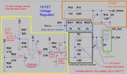
This may not be the appropriate thread to discuss the 18-fet voltage regulator circuit but since SAM-Pilot did such an excellent job drawing up the circuit and posting on this thread I will assume it’s OK to address circuit details here.

Thanks SAM-Pilot for the excellent job creating the schematic.
(See ... http://endless-sphere.com/forums/viewtopic.php?f=2&t=10312&start=195#p165673)

I made a few changes to your drawing, however, as shown here …

18-Fet_Voltage_Reg_Mod.jpg
I think this is closer to the “reality” of the actual circuit.

I am also thinking that the comparator circuit is operating in oscillation such that the primary transistor is either completely ON or completely OFF and NOT in the linear region. Therefore it would not be acting as a steady state variable resistor (and get hot) but would rather be a rapidly switching ON/OFF switch.
(My conclusion here ...
http://endless-sphere.com/forums/viewtopic.php?f=2&t=10312&start=240#p166337
is hopefully wrong).

If this is the case then it may be possible to mod the “switched series resistors” with a “transistor mod” to allow safe "any voltage" operation from LVC=30V to Max bat =100V.
The (hot) base series resistors may still need to be replaced, however, for the higher voltage ranges.

I only have fuzzy pics of the 18-fet board (I do not own one) and I have been waiting a LONG while for someone to attempt to draw up the 18-fet voltage regulator circuit.
Thanks again to SAM-Pilot.

Anyway … a new thread may in order to discuss the 18-fet voltage regulator circuit.
I leave that issue to methods and the other folks who have put in a lot of time, money and effort to bring these 18-fet boards to an economic viable reality.


Cheers,
Knuckles
 
Lyne is the man!
Kunckles is also the man!

This thread is a place to discuss anything that you guys like. Software, hardware , pretty ladies...

Keep it up guys.

-methods

P.S. Geoff - Keywin and I had a clear deal worked out. It was agreed that he would deliver a translated version of the software. He did not deliver and I am no longer trying to communicate with him. Water under the bridge now that we have Lyen to help. We can easily search-replace the Chinese for English in a hex editor. I am sure someone else will get to it before I do.

OFFER: 18 free IRFB4110's to the first person who posts a near-perfect English version of the software (You pay for shipping)

Clarification: Working English version... No cheesy tricks :roll: :mrgreen:
 
Good luck editing with a hex editor. You can't even select the titles. This definitely seems to require someone with either an inordinate amount of time or someone who knows Chinese and knows how to work a Chinese hex editor.
 
hence the offer :lol:

Time is something that I have NOTHING of... :cry:

I have 35 controllers and not a single one for myself.
I dont even have en ebike right now :evil:

-methods
 
I am starting to ship quite a few kits now.
For those who are starting to assemble, I might make this suggestion:

Last night I built up a controller using grommets instead of the rubber plugs supplied. (which suck)
I grouped the phase and hall signals on the right
I grouped the power and throttle/ca/brake signals on the left
The grommets made the build about 100 times easier so I am thinking of including them as standard.
To achieve water resistance some RTV can be applied after everything is checked out.

I dont have the grommet size in front of me but it was so over sized that I could just barely squeeze it in the hole.
It fits "snug" around 3 10AWG wires.

I have been working on a big long "hints and tips" and I may post that up soon.

-methods
 
Guys.. I may have a chance to recover my broken modified controller!

today at work i swaped the infineon 116A chip with the crystalyte 18 mosfet controller chip.

Guess what..!!

Before swaping.. the controller 5V rail was draining 210mA... and then it only draw 40mA at 33Vdv input..

The status LED is ON.. I really dont have any infineon error code.. but i hope that mean everything is ok :|

Please pay attention to that: the controller aluminum case slide that fix the board in place are responsible for the problem i hhad.. looking closer to the pcb trace i saw that the Vcc L and main VCC and 5V was shorted! by the case!

I recommand you to put some kapton tape to protect the trace!

next step.. going back to home and test that controller with the IC swap done!!

Doc
 
Good job doc.
Please start off with a current limited supply.......... :eek:


Just to clarify - It should be made clear that Doc went over the top with his board modifications. I have assembled 6 controllers that I consider "fit for 100A" and I did not have any isolation issues. I did not use any Kapton tape. I believe that the combination of doc using different size copper heat sink (shifting over the board) and extreme overbuilding of the fet power trace (shorting V to case) lead to this situation.

Everyone should absolutely use kapton tape to insure isolation
but - just so that we are clear - the boards will likely maintain isolation if built to a less extreme specification.

-methods
 
methods said:
Everyone should absolutely use kapton tape to insure isolation[/b] but - just so that we are clear - the boards will likely maintain isolation if built to a less extreme specification.

-methods


For some reason, I like assurances that are greater than "likely".
 
The point is that the boards are not "Grinding" against the case in a normal build.
If they were, then Kapton tape would not be a good enough solution in a high vibration environment.

If there were positive contact then we would need to take corrective action -
Since there is a "chance" of contact we take precautionary action.

There is a difference :mrgreen:

-methods
 
methods said:
The point is that the boards are not "Grinding" against the case in a normal build.
If they were, then Kapton tape would not be a good enough solution in a high vibration environment.

If there were positive contact then we would need to take corrective action -
Since there is a "chance" of contact we take precautionary action.

There is a difference :mrgreen:

-methods

So, let's put this in the reference point of a common-place customer. If they buy this and don't do anything beyond whatever easily followable standard installation procedures, there's a perceivable "chance" something will short? Or there's pretty much no chance? Or is there a perceivable chance, but the chance is so small as to be negligible (I.e., if 1000 were sold, and every normal customer installed correctly, then virtually no one wouldn't have a problem. Or would it be more like 1 or 2? Dear god, please don't say 100! I know you "like to know what you can get away with" but I'm not exactly comforted if they're built that way in stock form.)
 
Doctorbass said:
Guys.. I may have a chance to recover my broken modified controller!

today at work i swaped the infineon 116A chip with the crystalyte 18 mosfet controller chip.

Guess what..!!

Before swaping.. the controller 5V rail was draining 210mA... and then it only draw 40mA at 33Vdv input..

The status LED is ON.. I really dont have any infineon error code.. but i hope that mean everything is ok :|

Please pay attention to that: the controller aluminum case slide that fix the board in place are responsible for the problem i hhad.. looking closer to the pcb trace i saw that the Vcc L and main VCC and 5V was shorted! by the case!

Doc


hi doc
what you found was what I discribed in one of my earlyer posts http://endless-sphere.com/forums/viewtopic.php?f=2&t=10312&start=225#p166113 glad you've got it sorted now.
Methods I agree with you docs short was caused by overkill when adding wire to the track the controllers from methods will not have that problem.
Geoff
 
Guys.. THE CONTROLLER WORK !!.. ALIVE AGAIN... REPAIRED !!..

NOW WITH THE SAME INFINEON CHIP BUT FROM A CRYSTALYTE CONTROLLER.. THE DISGNOSTIC LED IS ON(continuous).. and wasn't with the infineon..

:mrgreen: :mrgreen: :mrgreen: :mrgreen: :mrgreen:

I feel it's like i saved 10 hours by avoiding to rebuild the crystalyte in crazy high power upgrade !!!! :mrgreen: :mrgreen: 8)


But the trouble that caused that is due to an ingeneering problem.. the trace DOES slide to the track of the case!.. and that's the edge at the end of the controller track that removed the varnish and exposed the cooper to the aluminum case. NORMALLY A GOOD PCB DESIGN WOULD HAVE PCB TRACE CORRECTLY SPACED FROM THE CASE TRACK..

I'm now 100% sure.. the beefy trace i added can't modify the force applied to the board and the case track.. and this is not what caused the track to short..

The story i think was that by removing and inserting the board many times into the case.. that makes the thace to lose their protective varnish skin by being dammadged by the short edge of the case track ends...


But.. anyway.. I now have a 100% functional crystalyte/infineon hybrid controller! :twisted:

now let's go back to finish the battery job ! :twisted: :twisted:

Thanks for investigating to help me solving that!

you all know now that the crystalyte 116A IC can replace a 116A on infineon controller.. after all.. in both controller this is the same infineon IC 8)

Doc
 
Good to hear your controller is working again.
Now we are sure of the short circuit between Vcc and 5V, I recommend changing the 25V electrolytic capacitor for safety reasons.

@Knuckles
Thanks for your comments on my schematic. I will check the added resistors, as soon as I have the PCB on my desk.
It is a pleasure to see all you guys using my work!
 
Back
Top