Building a motor

Bassackwards derp, I keep forgetting to think inside out. You're right they don't spin and won't move air.

You would only need 22 teeth, no? When you say better resolution do you mean a larger diameter? The pictured discs I posted are about 2" / 50mm and I think .048" thick, it's been a while. You can laser cut metal very thin and very accurate, should be able to do .001" on a good machine. Nissan used 360 window CAS discs to time some of their engines with optical encoders that are about 50mm. You can note pierce points and what surfaces to avoid tie ins on so they won't throw off your edges / resolution in fab. It should be much more accurate than the pc board is.
If you use vertical optical sensors and cut some teeth next to the magnets that could work too.
 
If going encoder i would want probably 50 or more pulses per pole pair. My plan is 26pole (13 pair) so I'd want 650 pulses minimum. If you're thinking of making a 26 pole disc with 3 sensors to emulate a hall, then yes the disc would work. Hadn't thought of that. Bulkier but cheaper. Vertical optical could be really nice if desperate to avoid hall effect.

Actually the halls/opto replicating halls don't need to be accurate for FOC, only repeatable. During setup on the controller i made it sweeps through a whole sin wave and finds the near exact position of the halls. I think VESC does some variant of this and other proprietary ones i guess do too.

You can adjust in real time to account for constant error in the quadrature components with great accuracy but what's much harder is dealing with the noise and jitter induced by current so one way or another you need to distance the sensor from the magnets and coils.

The design already leaves a lot of space for discs etc.

Just need to send the dxfs to the stator company and see the damage now
 
One thing that's put a damper on this is that very recently (thinking last month but I'm not sure) this has appeared:
https://www.antinnotech.com/products/ant-innovation-at-12070-lightweight-brushless-dc-outrunner-motor-15kw-with-40kg-thrust-for-electric-paramotor

This isn't far off what I'm designing tbh and at 330usd... It'll be cheaper than building one probably 2x and 50x if i value my time (and half the price of neumotor I was going to buy...)

I still really want to build a motor though. And the ant inno one isn't quite making sense. Specs all way out of whack with reality, phase resistance listed is 10x what I'd expect.
 
If you went with that high of a number of pulses you would need a zero point for each, no?
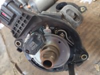
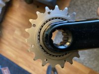
I was thinking you were doing what everyone else does for motors like these. I think there are some optical pickups that are stacked, 2 layers of sensors. The Nissan cas is like this, Mazda distributors in the '90s too. You could have the "normal" 1 pulse per magnet that most of these motors have with three pickups and a second group of windows /teeth with however many you want. Nice thing with optical is you can SLA print a bunch of chopper wheels to try whatever you need. FDM might work too if it's not too tight. I attached a Nissan sr20 distributor for the idea reference (2 trigger layers.) Zoom in, the fuzzyness is the 360 window area.
 

Attachments

  • IMG_20200315_105741.jpg
    IMG_20200315_105741.jpg
    240.3 KB · Views: 968
mxlemming said:
One thing that's put a damper on this is that very recently (thinking last month but I'm not sure) this has appeared:
https://www.antinnotech.com/products/ant-innovation-at-12070-lightweight-brushless-dc-outrunner-motor-15kw-with-40kg-thrust-for-electric-paramotor

This isn't far off what I'm designing tbh and at 330usd... It'll be cheaper than building one probably 2x and 50x if i value my time (and half the price of neumotor I was going to buy...)

I still really want to build a motor though. And the ant inno one isn't quite making sense. Specs all way out of whack with reality, phase resistance listed is 10x what I'd expect.

"Max power 15W" I think marketing needs to meet with engineering and fix a few things.
 
Jrbe said:
mxlemming said:
One thing that's put a damper on this is that very recently (thinking last month but I'm not sure) this has appeared:
https://www.antinnotech.com/products/ant-innovation-at-12070-lightweight-brushless-dc-outrunner-motor-15kw-with-40kg-thrust-for-electric-paramotor

This isn't far off what I'm designing tbh and at 330usd... It'll be cheaper than building one probably 2x and 50x if i value my time (and half the price of neumotor I was going to buy...)

I still really want to build a motor though. And the ant inno one isn't quite making sense. Specs all way out of whack with reality, phase resistance listed is 10x what I'd expect.

"Max power 15W" I think marketing needs to meet with engineering and fix a few things.
Neu motor claimed even more from a similar size motor (80mm diameter stator 57mm length, this I think is 100mm diameter 40mm) . Madin88 built his bike using that and claimed great success. The air gap area ultimately defines the power so the ant inno is in very much the same ball park as the neu (4000mm2vs 4500mm2) and similar results can be expected. Edit: i can see i missed a factor of pi here but the ratio stands.
https://neumotors.com/motors/neumotors-8000-series-bldc-motors-7500-30000-watts/ this says 22.5kW. Complete bullshit but madin88 set the expectation at 10kW ish.
 
I can't wrap my head around 13hp / 10kw on a bicycle. It seems like power to weight should go out the window when the weight is 90% you. My wife has a 390 KTM Duke. 300lb & 44hp for a 12:1 weight to power. To get the same on a bicycle it should have around 16hp. I've ridden 3:1 weight to power motorcycles but a 16hp bicycle just seems nuts.

$330 is hard to beat unless it's junk. I'm sure there's a lot to be learned in building a motor yourself. Hard to put a dollar value on real learning that expands your skillet and understanding.
 
mxlemming said:
Jrbe said:
mxlemming said:
One thing that's put a damper on this is that very recently (thinking last month but I'm not sure) this has appeared:
https://www.antinnotech.com/products/ant-innovation-at-12070-lightweight-brushless-dc-outrunner-motor-15kw-with-40kg-thrust-for-electric-paramotor

This isn't far off what I'm designing tbh and at 330usd... It'll be cheaper than building one probably 2x and 50x if i value my time (and half the price of neumotor I was going to buy...)

I still really want to build a motor though. And the ant inno one isn't quite making sense. Specs all way out of whack with reality, phase resistance listed is 10x what I'd expect.

"Max power 15W" I think marketing needs to meet with engineering and fix a few things.
Neu motor claimed even more from a similar size motor (80mm diameter stator 57mm length, this I think is 100mm diameter 40mm) . Madin88 built his bike using that and claimed great success. The air gap area ultimately defines the power so the ant inno is in very much the same ball park as the neu (4000mm2vs 4500mm2) and similar results can be expected.
https://neumotors.com/motors/neumotors-8000-series-bldc-motors-7500-30000-watts/ this says 22.5kW. Complete bullshit but madin88 set the expectation at 10kW ish.

What would be the math to figure the max torque out of the motor based on the airgap surface area and steel max permeability and airgap diameter? How big a motor do u need for such and such torque output? I see motor claims all over for max amps but never see a graph of amps to torque. That’s a solid number instead of motor marketing hype and I think they’re all using similar electrical steel. I’d think that’d maybe be the best start as apposed to possibly overdoing the motor size and gaining unnecessary weight and maybe ending up more inefficient.

Or maybe instead of finding a stator, which is hard to do, you could get one of these “frameless” motors and build around them. Although I don’t see how these rotors are possible to mount https://www.magneticinnovations.com/direct-drive-electric-motors/torque-motor-direct-drive/small-high-torque-motor/


Or the ant motor you posted I bet you can get in parts and they sold me parts. https://www.antinnotech.com/products/ant-innovation-at-12070-lightweight-brushless-dc-outrunner-motor-15kw-with-40kg-thrust-for-electric-paramotor
It’s big and surely will get the torque you’d want (a claimed 250 amps) but again maybe with a mid-drive you’d be better off with the smaller stator they have with .15mm lams and spinning it faster? I never see .15mm lams available
 
Hummina Shadeeba said:
What would be the math to figure the max torque out of the motor based on the airgap surface area and steel max permeability and airgap diameter? How big a motor do u need for such and such torque output? I see motor claims all over for max amps but never see a graph of amps to torque. That’s a solid number instead of motor marketing hype and I think they’re all using similar electrical steel. I’d think that’d maybe be the best start as apposed to possibly overdoing the motor size and gaining unnecessary weight and maybe ending up more inefficient.

Or the ant motor you posted I bet you can get in parts and they sold me parts. https://www.antinnotech.com/products/ant-innovation-at-12070-lightweight-brushless-dc-outrunner-motor-15kw-with-40kg-thrust-for-electric-paramotor
It’s big and surely will get the torque you’d want (a claimed 250 amps) but again maybe with a mid-drive you’d be better off with the smaller stator they have with .15mm lams and spinning it faster? I never see .15mm lams available

The ant guy has been really useful so far/sent me details and arranged a modified shaft for my application. Going to set me back 400$ by the time postage accounted for though:(

The 12070 stator is 105mm diameter and 41 height.

Now... The math. I've been musing a quick way to get an answer for max torque. I'm typing on my phone so... This might be bullshit.

Step back to GCSE... F=BIL. Well we have magnets and wire and lengths so... What if we looked at the number of stator slots, the saturation flux the number of turns... The radius...

For this 24 slot stator I've got 24x2 wires with say 4 turns (guess from looking at pics of the ant motor), 100A ish. Steel saturates around 1.5T... the iron essentially projects the copper to the shear line, the air gap.

So B=1.5T
I=100A
L=24x2x4x0.04 = 7.68m of wire normal to field.

F= 1152N
Torque=FxR is 0.05x1152=57.6Nm

This is quite high an estimate but there a few factors to consider...
1 the flux is sinusoidal so there's a factor of 2/pi (from the integration on sinx from 0 to pi)
2) the surface flux has to reduce with the ratio of the tooth angle to the spokes thickness, roughly 4mm to 13mm

57.6x2/3.14x4/13= 11.3Nm

Now comparing to kV and kT...
80kV (typical for this motor) x2xpi/60 is 8.4rad/s/V
kT is the inverse is 0.12Nm/A

X100A is 12Nm

That's a lot closer than i was expecting to freehand on a phone...

So how many amps can you feed in?

Enough that... You saturate the iron. But doesn't the magnetic field already provided a large field? Yes... But it's in quadrature to the current (otherwise it doesn't produce torque...)

From memory... And I really have shit all idea what I'm talking about at this stage...
H=NxI
B=mu0 x muR x H=1.5T when it starts to saturate significantly.

I=1.5/(mu0 x muR x N) = 1.5/(5e-3 x 4) = 75A using mu from Wikipedia electric steel https://en.m.wikipedia.org/wiki/Permeability_(electromagnetism) which is worrying given the insane range of mu for different steels...
M50 electric steel from NKS shows muR as 2200 not 5000 so the saturation current becomes 170A and the peak torque from that motor is about 12x1.7=20Nm.

This again seems like a reasonable number although less (half?) what i was expecting. It's not several orders of magnitude out...

I'm going to leave this here. I'll muse on it some more and see if i wake up at some point realising this is all retarded.

If you up the max magnetic field to 2T, by which point there will be huge losses then you get increase of (2/1.5)^2 =1.77x and there will never ever be any more torque however much current you push.

But maybe once again I'm talking nonsense.
 
what about a simple formula to figure the max torque a motor can put out before the steel starts to saturates. if the motor stator is 100mm diameter and 40 tall, circumference x the length so 314x40=12,560 square mm i think, and times 1.3 tesla or just before it starts to saturate, x the radius = a max leverage/torque. some math like this possible?

maybe it assumes too much related to the steel and stator shape


and copper losses more so dominate but with enough good cooling...

the bike im making has a rigid rear end, how you think the ant 80100 will do? almost always riding roads but the roads often are bad. its got a skirt bearing. and belt tension for 15mm GT 5mm pitch stuff, which i read you saying was a lot for belts on these motor bearings.
this goofy motor has a skirt bearing and a bearing on the shaft on the same side. but will see how this 80100 motor does before i maybe make something. doing a slotted motor mount to get belt tension and then your stuck with maybe even one motor available out there in the world or you have to make a motor just to be able to make it fit your motor mount.
 

Attachments

  • Capture.PNG
    Capture.PNG
    38.6 KB · Views: 782
  • Capture.PNG
    Capture.PNG
    47.2 KB · Views: 779
Hummina Shadeeba said:
what about a simple formula to figure the max torque a motor can put out before the steel starts to saturates. if the motor stator is 100mm diameter and 40 tall, circumference x the length so 314x40=12,560 square mm i think, and times 1.3 tesla or just before it starts to saturate, x the radius = a max leverage/torque. some math like this possible?

maybe it assumes too much related to the steel and stator shape


and copper losses more so dominate but with enough good cooling...

the bike im making has a rigid rear end, how you think the ant 80100 will do? almost always riding roads but the roads often are bad. its got a skirt bearing. and belt tension for 15mm GT 5mm pitch stuff, which i read you saying was a lot for belts on these motor bearings.
this goofy motor has a skirt bearing and a bearing on the shaft on the same side. but will see how this 80100 motor does before i maybe make something. doing a slotted motor mount to get belt tension and then your stuck with maybe even one motor available out there in the world or you have to make a motor just to be able to make it fit your motor mount.

I'll try to work out a formula. For the moment I'm in work carnage and have a norovirus 2 year old so time...

For the riding you describe, you'll probably have decent luck with the 80100 motor. What size is the 80100 lamination stack? My red 8080 is a 40mm stack. Just gear it down as much as you can, run it with vesc or something like that.

The belt situation is tricky. 5m works absolutely fine except under braking where it turns out there a long-standing belt problem with gear up power transfer. 8m is basically bulletproof but high reduction ratios are hard, best I've managed is 15 to 93 and the belts aren't meant to be used on 15 tooth..

I'm working on a reverse spring tensioner for the 5m but until that works well I'd advise 16 tooth 8m to a massive 120 or so rear (for 26 inch wheels).

The skirt bearing is useless it doesn't support the shaft atall. I've completely gutted the bearings in one red motor, so you'll definitely want an extra shaft support bearing right next to the pulley. My next design will double this bearing up as a tensioner.
image.png

I just ordered the ant innovation 12070. Far more than i wanted to ever pay for this project but meh. It's basically the same power capability and a bit more torque than the neu 8057, weighs a bit less and Arvin at ant actually seems to understand basic requests...

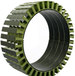
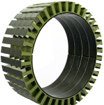
On building this motor, custom stators are out, the companies i asked to product the dxf of the design above wanted over 1kusd for 5 stators so i basically have to find off the shelf. I've found some 36n stators but I'm really struggling with a magnet config to suit. Might be able to do 38 pole with halbach 4mmx4mm magnets.

Ant wouldn't sell me their stator and frankly i don't like the design from a magnetic perspective anyway.
 
Have you had any luck in talking to these motor mfgs finding any motor variables that would help calculate iron losses? They would be very useful in determining the ideal RPM ranges we should be gearing for as it seems places like Ant sell Kvs to run them at any RPM we want. In particular it would be great to know how these compare with these larger diameter, higher pole count motors where the ideal RPMs could be lower which would make gearing them a lot easier. I'm still learning about all this motor stuff so I could be wrong but I think that the no load current they give is not enough to calculate the iron losses from without having more data points to determine the slope (at least without knowing which Kv motor they are talking about).
 
scianiac said:
Have you had any luck in talking to these motor mfgs finding any motor variables that would help calculate iron losses? They would be very useful in determining the ideal RPM ranges we should be gearing for as it seems places like Ant sell Kvs to run them at any RPM we want. In particular it would be great to know how these compare with these larger diameter, higher pole count motors where the ideal RPMs could be lower which would make gearing them a lot easier. I'm still learning about all this motor stuff so I could be wrong but I think that the no load current they give is not enough to calculate the iron losses from without having more data points to determine the slope (at least without knowing which Kv motor they are talking about).

None of them know anything. I've tried but they don't even have access to the drawings for their motors.

I'm pretty sure that they're all made in the same factory which i suspect is owned by Donguan RC Hobby but I'm not sure. Ant innovation etc provide an inlet to getting custom/variants of the standard parts.

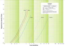
I did however ascertain that they're using kawasaki or baosteel 0.2mm laminations, and I got a data sheet showing the in losses as a function of eHz and field strength per mass of material. The losses to iron aren't as high as we are assuming, at 3krpm, its something like 30W, but that changes hugely with magnetic field strength.
0.2mm lamination loss.PNG

It is also becoming clear to me that higher pole count might be a good idea. More winding hassle, BUT, the torque I think scales with number of poles, without increasing saturation; the torque is proportional to rate of change of flux linkage... more poles = more rate of change per angle.

I can get this 100mm stator:
36n stator.PNG
Which I initially discarded due to excessive pole pairs, but actually it might work really well for the application and more poles = less yolk iron on the stator = lighter... Could be a serious win in the end.

Think I shall combine with 4mmx4mm magnets (found a sensible source finally) in Halbach array:
101mm*pi/38PP = 8.35mm space per pole.

Could work well... Same overall dimensions and power as the original plan but with this winding instead:
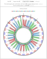
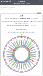
36n38p winding.PNG
 
will core losses increase with higher current even before saturation? makes sense but never see it mentioned and seems skipped in rc plane calculators or simulators

in my looking at the benefits of greater poles it doesnt increase torque other than with the many poles the magnets are then smaller so you can increase your airgap diameter by maybe a couple millimeter with the smaller magnets or something but that's it. cheaper, lighter, and better control though

seems awfully high flux density with the kawasaki steel and it doesnt even show any saturation effects at 1.6T. or am i wrong? it looks like it even improves from 1.6 to 1.8T which id think was way into saturation.
 
Hummina Shadeeba said:
will core losses increase with higher current even before saturation? makes sense but never see it mentioned and seems skipped in rc plane calculators or simulators
I think not necessarily, since the permanent magnets provide the most significant field at lower current, and the current induced field just leads the magnet induced field so overall, the field strength doesn't increase (I think...) Or maybe it increases with

(current induced stator field^2) + (magnet induced stator field)^2)^0.5

Hummina Shadeeba said:
in my looking at the benefits of greater poles it doesnt increase torque other than with the many poles the magnets are then smaller so you can increase your airgap diameter by maybe a millimeter with the smaller magnets or something but that's it. cheaper, lighter, and better control though
I am fairly sure (but not certain) the (possible, limited by saturation) torque does increase with more poles.

Hummina Shadeeba said:
seems awfully high flux density with the kawasaki steel and it doesnt even show any saturation effects at 1.6T. or am i wrong? it looks like it even improves from 1.6 to 1.8T which id think was way into saturation.
Baosteel, and I have no idea.

I guess once saturated, the incremental losses drop off since the H field can greatly increase? I kind of thought it would be the other way round, but my understanding is in flux.

EDIT:
A few hours after writing this, and reading through https://www.et.aau.dk/digitalAssets/292/292916_unified-torque-expressions-of-ac-machines---web-version.pdf
I retract my second statement that max torque possible increases with poles.

After more thinking, the assumption and experiment I based this on (lining up 2 large magnets vs 8 small magnets of the same total mass and observing the shear force was larger on the small ones) and that torque is proportional to rate of change of flux linkage (I think it is, but this breaks down at saturation, which is what we are discussing) has a flaw - I was assuming same thickness of magnets and same air return path.

If you add large lumps of iron to the equation, everything changes. The flux can link much more effectively from pole to pole, and the overall integral of rate of change of flux around the circumference of the stator remains the same.

So my revised "statement" (still with less than complete certainty) is that torque will remain the same for a given airgap, regardless of poles, PROVIDED there is sufficient iron to link the flux back to the opposite pole.

So for a 1 pole pair motor, you can get the same torque as a 2,4.....2000 pole pair motor, but the required thickness of iron to relay the magnetic flux will increase in inverse proportion to the number of pole pairs and so the mass of the motor will increase. Similarly, the limiting factor being the iron losses to frequency and copper fill, the power of the motor will increase dramatically with pole pair decrease... but there will be a pile more iron.

Overall, instantaneous power capability scales with weight, and instantaneous torque scales with airgap.

So for our ebike things, we could probably express the weight of the motor required based on the power (speed) we want to get to, and the air gap radius based on our possible gear ratio we have.

Apply practicality... and we have a set of workable parameters.

My first stator (24n) and the one I found last night (36n) will produce the same torque. The second one weighs substantially less (about 2/3 as much) so will produce about 2/3 as much power before the iron losses become equal, an will go 2/3 as fast...

A lot of thinking and logic to come to the same conclusion as always... There is no free lunch, you need more mass of motor to go faster, you can only eliminate the wastes and make marginal improvements. Who'd have thought it...
 
https://www.anttilehikoinen.fi/technology/electrical-engineering/pole-count-good-bad-ugly/

https://www.rcgroups.com/forums/showthread.php?2934319-motor-with-more-poles-give-more-torque-again

I’m also wondering what’s an ideal rpm range for efficiency but figure it’s a toss up depending how heavy handed on the throttle or how often at full speed. Will log and figure,unfortunately after it’s all built already.

I forget names and I never found the thread/details but of course someone (mud?)has been down this road on the forum and supposedly 8k rpm is a maximum rpm for a typical 12x14 motor before ..things go more south due to high switching frequency, but I think more so than just the eddies would lead u to believe. But I don’t know what I’m talking about and would like to find the thread here. I’ll be hitting near 9100rpm with the 12:1 gearing im already locked into so will see the no-load losses at least with that soon

As u can tell I’m pretty interested in this topic.
 
Hummina Shadeeba said:
https://www.anttilehikoinen.fi/technology/electrical-engineering/pole-count-good-bad-ugly/

https://www.rcgroups.com/forums/showthread.php?2934319-motor-with-more-poles-give-more-torque-again

I’m also wondering what’s an ideal rpm range for efficiency but figure it’s a toss up depending how heavy handed on the throttle or how often at full speed. Will log and figure,unfortunately after it’s all built already.

I forget names and I never found the thread/details but of course someone (mud?)has been down this road on the forum and supposedly 8k rpm is a maximum rpm for a typical 12x14 motor before ..things go more south due to high switching frequency, but I think more so than just the eddies would lead u to believe. But I don’t know what I’m talking about and would like to find the thread here. I’ll be hitting near 9100rpm with the 12:1 gearing im already locked into so will see the no-load losses at least with that soon

As u can tell I’m pretty interested in this topic.

I noticed. It's now about 4 years since your post about the same on the rc forums. My interest only really started a few weeks ago when i decided i really really needed a bigger motor. Before that i was like: "there are motors. They spin and i can apply FOC to them"

It seems like 1000ehz is the magic number so for 14p that's 8500rpm with 0.2mm steel. Your skirt bearing isn't going to like that though, and FOC doesn't really work at that speed.

Can you spin up to that speed and measure the no load power?

How are you getting 12:1 ratio? Dual stage reduction? Share a pic please.
 
Using the freewheeling crankset with this double freewheel drilled so can use the 17tooth. Have a frame being custom made w this motor mount in the seat tube. I havent wound the motor yet so maybe will wind for lower kv and will see the no-load draw at around 9000 rpm. And then with voltage sag and load on the motor I’ll likely drop rpm to around 8000 or lower. And then this is a .15mm lamination motor and maybe good faster. Will see. You mention problems with foc n concerning


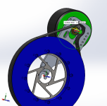
Vesc does 75v and 135 amps. Will do 70v. 15mm wide 5mm pitch belt.
Gearing is 17x50 teeth for second stage n chain. First stage is 20 and 86 I think.
 

Attachments

  • D67B621E-C49F-45C4-9F2F-1DD2F4E0D871.jpeg
    D67B621E-C49F-45C4-9F2F-1DD2F4E0D871.jpeg
    22.7 KB · Views: 710
  • A9B67E53-44CB-4C32-80DB-4AAC1942BC73.jpeg
    A9B67E53-44CB-4C32-80DB-4AAC1942BC73.jpeg
    288.4 KB · Views: 710
Hummina Shadeeba said:
Using the freewheeling crankset with this double freewheel drilled so can use the 17tooth. Have a frame being custom made w this motor mount in the seat tube. I havent wound the motor yet so maybe will wind for lower kv and will see the no-load draw at around 9000 rpm. And then with voltage sag and load on the motor I’ll likely drop rpm to to maybe around that 8500. And then this is .15mm lams n maybe good faster. Will see. You mention problems with foc n concerning


Vesc does 75v and 135 amps. Will do 70v. 15mm wide 5mm pitch belt.
Gearing is 17x50 teeth for second stage n chain. First stage is 20 and 86 I think.

You are going to have a belt drive spinning at 2000rpm on that freewheel? They are meant for like 80rpm I think. Also,that is going to put one hell of a stress on your chain. Might be very effective until something snaps!

Don't get your trousers caught in it.

1000eHz = 30 VESC switches per sinusoidal period. That is quite hard to control, and the current won;t be very sinusoidal. It will work OK though.

A lot of the advantages of FOC go out the window when you have ultra high speed, the quietness, the torque ripple etc...

I don't think VESC can do 180kerpm in FOC mode, I think it is just for BLDC mode. 8500rpm = 60kerpm is fine though.
 
Yes I guess about 2000rpm for the freewheeling cranks. I think that should be fine for the bearing in it and don’t think an issue there. I think the load on the belt is within specs assuming no added use-factor (although I think with a bike it should be higher use-factor), and the chain I don’t think a problem and still a lot of speed and not much torque. I figured the wheel freehub ratchet would be the weak link.


I saw u know about escs and their efficiency. I’d rather do foc. I guess will see with the no-load draw and that will reveal, or will the current put through be more inefficient at that speed and I won’t see that inefficiency without a load? Bike will probably be so loud anyway maybe square waves will be worth doing and will compare at least the no-load draw..and can compare the two programs on my route.


But then again maybe even if it’s inefficient at the higher erpm (due to foc or just eddies) I’ll rarely be at that speed and a trade off for low copper loss and a boon anyway. All vague speculation based on little knowledge
 
I bought the only stator I could, this:
36n stator.PNG

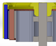
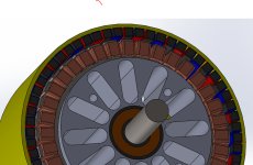
I am going to try to assemble the motor like this, with a halback array to avoid back iron, which will be PITA to get. Unfortunatlely, this ends up with about 600g of magnets, but it's still far easier than getting back iron in the exact radius.

Motor 36N30P Halbach X-sec.PNG
Motor 36N30P Halbach.PNG

Following the previous discussions and realising torque is proportional to airgap radius and not pole numbers, it makes sense to kee the pole pairs as low as practially possible. 36N is normally wound as 42P, which as far as I can see will not help anything. No more torque, just higher commutation rates.

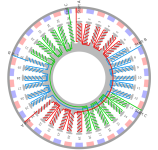
There is a nice arrangement that's easy to wind, with a fairly low PP number for 36N - 30P. It keeps a good winding factor (optimal is 34 but this was really hard to arrange magnets for neatly and more PP = more iron loss)
36N30P winding arrangement.PNG


Back onto the theory, it seems that the iron losses increase dramatically with the field strength the magnets impart on the iron. In the graph previously posted, at 400Hz, it seems that in going from 1.5T to 1T the losses drop from 30W to 12W/kg.

This would lead me to think that running into the field weakening regime would decrease the iron loss (though it would increase the copper loss) so there might be significant benefit to getting your higher speeds from field weakening rather than higher voltage at extreme eHz.

e.g. at 1000Hz, you could either add 50% voltage, or suppress the field by 33% to get 50% extra speed. The field weakening would reduce the iron loss from ~110W/kg to 40W/kg. How much current would you need to achieve this, and how much loss? well... Not sure.

Of course your torque producing capability decreases as well, but as long as you are needing speed more than torque, this seems like an option.

Is this a realistic and meaningful proposition?
 
Higher winding factor with LRK winding and wye. Easier to wind. Maybe with how short the stator is its not ideal in making slightly more end turns wire but bet you can get more wire on to compensate as you just wrap the tooth as much as you can as apposed to having to leave room for the neighboring teeth


With 30 and 36 it’s a big spread and more cogging. Would that cogging torque be a resistance when powered as well? If not maybe 30 and 36 would better allow room for hallbach being few poles, I guess that’s the point. Emetor software will let u simulate a hallbach if u can make the dxl file which is easy for most.

I don’t have answers ..only more questions... is skin effect a loss at the erpm you’d be doing?

How physically will u make the hallbach? On rcgroups guy shows a cool “clip” to hold them. A lip to get them behind. I think maybe the only way to assemble them and otherwise the magnets do what they want. Not much shown though
 

Attachments

  • 2EAD21CB-64A6-40B4-B739-27E7C9536B4A.png
    2EAD21CB-64A6-40B4-B739-27E7C9536B4A.png
    93.3 KB · Views: 642
I have never really considered this single layer winding option, no one ever seems to do it, so I assume it must be bad, but I can;t really see why. If anything, and particularly with this N and P option, it looks intuitively like a really good wind, and less fiddly (though the same amount of turns of actual winding, so the effort won;t change much). The winding factor is also considerably up (from good to very good).

I might try just winding it with a single strand of wire in each configuration and see if there are any noticeable differences.

Won't single layer have worse copper to stator conduction?i.e it will dissipate heat less well?

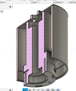
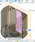
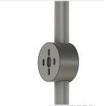
If you see the design, it currently has a recess into which a 50mm long magnet goes (1cm extra length for locating, the extra cost was minimal). I will print a little clip thing to hold the other end if I need to; I have never made a Halbach array, and hope that they will all push radially outwards, but I suspect I will soon become disappointed...

Problem with getting high grade magnets is becoming apparent. I have found N35, but nothing higher.
 
I can imagine possibly worse transferring of heat to the stator from the wire with LRK although never heard of that as a reason not to use it (with good airflow transfer heat right off the wire and forget transferring to the stator.). The reason I hear for why not used is due to it having slightly larger end turns, so more wire at the top or bottom of the tooth where it’s said to not be as productive, so on a short stator the winding isn’t as ideal as a long stator. Yours being short. I’ve also seen a paper on this forum showing it having a less sine waveform but I think it would depend and generally people have good results with LRK. The biggest reason to do it being simply can get on my copper in my experience and it’s less complicated. Also less fault prone with a lot less contact between wires across different phases

Oo ok I think I see ur “clip”. Guy I saw do it had a clip on both sides but maybe good enough as you have it.

You shouldn’t have trouble finding stronger magnets. I get n45sh custom in bulk from China. I forget the name now but alibaba or I can find them if u want.
 
Hummina Shadeeba said:
I can imagine possibly worse transferring of heat to the stator from the wire with LRK although never heard of that as a reason not to use it (with good airflow transfer heat right off the wire and forget transferring to the stator.). The reason I hear for why not used is due to it having slightly larger end turns, so more wire at the top or bottom of the tooth where it’s said to not be as productive, so on a short stator the winding isn’t as ideal as a long stator. Yours being short. I’ve also seen a paper on this forum showing it having a less sine waveform but I think it would depend and generally people have good results with LRK. The biggest reason to do it being simply can get on my copper in my experience and it’s less complicated. Also less fault prone with a lot less contact between wires across different phases

Oo ok I think I see ur “clip”. Guy I saw do it had a clip on both sides but maybe good enough as you have it.

You shouldn’t have trouble finding stronger magnets. I get n45sh custom in bulk from China. I forget the name now but alibaba or I can find them if u want.

Please share the supplier. I'm having a nightmare with AliExpress and alibaba always ends up in retarded shipping costs
 
Back
Top