C Cab Hot Rod Power Advice

OK, SlowCo, how about this?

I didn't think I would like them mounted to the headlight buckets. But I do.
It helps break up the bulky look of the headlights.

They look a lot better than the 2D photos.


DSCN5227.JPGDSCN5228.JPGDSCN5229.JPGDSCN5230.JPG
 
ZeroEm said:
Them lights are bulky, more than imagined. They look good don't they. Gives your rod that attention grabber.

The photos make them look bulkier than in reality. Viewing them with the rest of the car, they are OK.
 
Removed the threaded insert to make way for welding on the light brackets.

Enlarged the hole where the wires will go on their way up the frame rail to the battery/converter.


The inner guide tube for the outer cover, that serves as the base for the headlights.


Outer 'pvc' cover installed. Also repositioned the support rods for the windshield.


Both covers on, sans headlights.


This went like clockwork, except for the toe in/toe out, changed. And by a large amount too.

I have no idea what caused it. I did remove the radius rods ( one side at a time, then replaced) to gain access to the insert, but they went back just as they came off.

Can be adjusted, but I sure would like to know how it became misaligned.
 
Discovered why the toe-in/toe-out was so out of whack.

The right side steering arm became loose. It was moving in the retaining slot/keyway.


This photo shows what it looked like before repair. I didn't do a good enough welding job the first time, so there wasn't enough material in the slot to hold very well.
I added additional weld material in the highlighted area below before any weld material was added. Then I spent a good portion of the morning filing until it, fit snug and tight.
Also completed a long-standing project of lengthening the connecting rod, and cutting the radius rod bolts down to size.

 
No sooner did I receive my 100' of 14 gauge wire (10 colors @ $36.33) and I run across this

https://www.ebay.com/itm/192903024630?_trkparms=amclksrc%3DITM%26aid%3D1110013%26algo%3DHOMESPLICE.SIMRXI%26ao%3D1%26asc%3D20210708121852%26meid%3D95cde56cba4842639576f8c066ce93f0%26pid%3D101112%26rk%3D1%26rkt%3D24%26sd%3D302621034745%26itm%3D192903024630%26pmt%3D1%26noa%3D0%26pg%3D2563228%26algv%3DSIMRVIMLRV5WebV1_0&_trksid=p2563228.c101112.m1982&amdata=cksum%3A19290302463095cde56cba4842639576f8c066ce93f0%7Cenc%3AAQAGAAAB8DIPX4Fc30ufBq%252FS%252BuBAcohfWMshCuxcNCM8pa6ogWpXDurDaoCZuNoQO6o0fXGzqmqoV0ZpnNcPPi9%252FCiYbZGkIzoZhffDNzvSRwdH1GdLtVOPz3tDPlYFU%252BkW9FvG7c435bdiU5k5RHGrJRM4RXUuNIBAABuzyNlUkNc3YnZovkr2RKk1yYEUTxwg4u91cYfD1j61JQOxXloEL6Q6VMtl8PxRE%252B0TfCLg0nB8eyD%252Fk8Cr2IrRSoYi%252BrYcBvjmk7GHlfNRf44wPsstC4Kmo3rG3vYIuv%252BMF63qh6%252F5KsDyRYjFXluhGAw1rjrDFcmffsfP0dnUf%252FCWzOe%252B1p%252BLpzf4N0aJpbWuvqH2tHBQFhlK9llrkypMobUdX4g5tkVC372DIOyaYZQwAg5P1ikr38p3C9lerCxHLKxyzZxUukrNRkvnY%252FMom0UWQjDj%252F%252BmDvV30SlOTsZA%252Fu3Qgn4krJl%252FiKTLRB0Ag9544hFrUj5gVCqpclmaxGJ4%252FvTw3GZmfICAY79QOhLJc1NxBH8GxBwRQA1S2W19iHC4rzYGxEe3gjw76DSXWLaSnuau1I%252FaQZy1Q9lodLZoqMtWQ3cYoCGYg%252Bbc31xniDGt1Pz2MFWUYC6%252FpdZ3dCyXwTRR0UOf1%252B%252FZ3FOflM9Q%252FCl0%252FoDCysvro%253D%7Campid%3APL_CLK%7Cclp%3A2563228

On the surface, this seems to be the smarter choice. And for less money - $33.55 out the door.
Comes with instructions as well. Although I don't really need all those circuits.
Shipping for return is free on the wires I got today.

Does anyone want to offer up an opinion as to changing to the new wiring kit?
 
Just an option. Don't construe this as expert advise. Unless that muscle car wiring kit fit a body style or type do see how it would be better unless it comes with a connector kit.

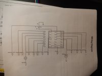
This kit has circuits for A/C, Ignition/Battery, Gauges, Brake switch, Flasher, Headlight, Wiper, Ignition, Battery/Hazard, Ignition On, ACC 1, Heater and, ACC 2, Fusible Link and, Butt Connectors.

The connectors are worth something. You will get a few that you don't need but maybe enought that you do. Depend if you have the connectors or not?
 
I have decided to go with this kit. Seems the better option, with all the fuses, semi-prewired, etc.
https://www.ebay.com/ipp/265409020053?transactionId=2828535557016&_trksid=p2047675.l48352

I have found multiple listings for the same or similar and finally put in an offer for this one.
I'm supposed to get the kit by Tuesday, but the seller is only 65 miles from me, so I might receive it by Saturday.

Thinking ahead to the future, I'm wanting to build an electrical component box that stays even with the body off. Or can be easily disconnected to facilitate its removal.
Remember now, if I live long enough, this chassis will be used for other body types.

The wiring, including the converter, will all go in this cavity back/under the seat.

DSCN4185.JPG

The box needs to fit between the two motors. Probably not more than 3-4 inches deep.
Access gained from a removable or drop-down door.

DSCN4345.JPG
 
Update - After some monkey business with the seller, I finally got the correct (I hope) harness on order.

And at the agreed-upon previous reduced price.
Should be here next Wed/Thu.

I have changed the location for installing the converter and fuse box.
Just ahead of the pillow block and behind the existing controllers.
I fab'd a box that fits in that area to hold each component.
Photos later.

I have started working on the schematic.
Seems simple enough at this point.
It has a relay installed, but I'm not sure what I should be using it for. Wiring it too.

This is just a rough idea of what circuits I may need.

12 VOLT SCHEMATIC.png

The instructions, that will be coming with the kit.
I won't be needing all that is in the instructions, but it helps to get started.

 
fechter said:
The relay would be useful for any loads that are too big for a switch. You may not need it.

Thanks, fechter

I'm eager to put together this wiring spaghetti, but really can't until I get the harness in front of these tired eyes.
Seeing is believing and makes it come clearer quicker.

I hope to lay out the wiring on a board, giving me a better sense of what goes where. Then hook it up and try it before installing it in the car.

May you and yours have a Happy Thanksgiving.
 
I'm working on where and what type (if any) switches I will need.
One thought is about the circuit breaker being used as the on-off switch.

This breaker will be concealed under the battery cover when completed.
I want to turn the battery on-off outside of the battery box, via repositioning the breaker or an external switch.

Some of my research on (you know the youtube academy of higher learning) tells me these types of batteries (specifically the type I have) are potential fire hazards. https://www.youtube.com/watch?v=rbkE4jxk3u8

Q1 - While in the learning phase of this type of power source, is it safe to leave the battery on, and use an external on-off for the system? I'm thinking this isn't a good idea.

Q2 - Will leaving the battery in the on position, on this type power source/battery - say out for the day at an event of some sort, have any adverse effects or on its longevity (depleting power), etc?

DSCN4243.JPGDSCN4244-1.jpgDSCN4246.JPG
 
Just_Ed said:
Some of my research on (you know the youtube academy of higher learning) tells me these types of batteries (specifically the type I have) are potential fire hazards.
All batteries are potential fire hazards. ;)

Q1 - While in the learning phase of this type of power source, is it safe to leave the battery on, and use an external on-off for the system? I'm thinking this isn't a good idea.
Is the existing battery switch something that completely disconnects the internal electronics (BMS, meter, etc) from the cells? If not, then it doesn't really matter whether the switch is inside the battery or outside it.

But you do want any fuses or circuit breakers as close to the battery output as possible in the wiring harness, so that they will disconnect it from the system in the case of a wiring short to prevent a wiring fire.


Q2 - Will leaving the battery in the on position, on this type power source/battery - say out for the day at an event of some sort, have any adverse effects or on its longevity (depleting power), etc?
Longevity? Unlikely.

Power usage over the day? Depends on how much power draw there is from any internal electronics in it that are normally shut off by it's internal power switch. That's probably pretty minimal, if there is any at all. Most of the time any internal electronics (BMS) are powered all the time by the cells, though some BMSs have a shutdown mode that draws very little current (microamps) vs their active current (milliamps).

If there is a voltmeter on the battery itself that is shut off by the internal switch, then it may draw a few dozen to a couple hundred milliamps, depending on design.

If it has a button you have to push on the meter to activate it, it probably doesn't draw hardly anything at all unless the button is pushed.
 
I'd just leave the main breaker off for storage. Don't forget to turn it on next time you want to run the car! (There's a story behind the advice).
 
I got the wiring harness this morning - earlier than expected.

All the components were there, BUT! there's always a BUT!.
The diagram they sent with the harness isn't much good. It definitely isn't accurate, in black and white, and some connections will need to be changed as I am not running those components.

Haven't figured out what PAPKLT/RADIO MEM stands for. Or what BPUPE power is?
And what is the difference between (IGN SWITCH RUN) and (IGN RUN/START)?
Also the diagram they sent shows #14 and # 28 connected, ????????

What has been a benefit is the wires are marked as to what they are intended for. Not that they will be used in that manner but it gives me a starting point.

DSCN5238.JPGDSCN5239.JPG

Here I am trying to make sense of where each wire is attached, what color they are, and how they labeled them. Have all the fuse sizes annotated and colored coded.

Next is to diagram out how the battery and converter hook up to this and then on to the switches/terminal blocks or components.

This isn't completed yet. Some terminals will be used for other components.
I still need to see how the fuse block is put together and how each connection works with other connections.

FUSE BOX WIRING-2.png
 

Attachments

  • DSCN5240.JPG
    DSCN5240.JPG
    5.5 MB · Views: 831
In the age of electronics, most things like radios with presets or memory they need some power when everything is off to keep the settings. This is the ghost draw we see on electronics. Clocks, alarms, keyless entry and ignition. If you don't plan on any of these things then don't worry.
 
I guess it doesn't come with an ignition key switch. With a car, the key has ACC, OFF, ON, START. The start position is spring loaded and returns to ON. You don't need the start line.

As ZeroEm states, the radio MEM line is always on regardless of key position.

No clue what BPUBE is.

I assume the relay was intended for a horn. I'm not sure if your dc-dc has enough power to drive a regular car horn. Possibly a small one.

I'd recommend tracing out the fuse block to see which terminals are internally connected. You can figure things out from there. Your layout needs to be a little different than a hot rod since your 12v is coming off the dc-dc. There are a lot of things there you probably don't need to use or worry about.
 
I guess it doesn't come with an ignition key switch. With a car, the key has ACC, OFF, ON, START. The start position is spring-loaded and returns to ON. You don't need the start line.

I have a key switch that came with the controllers. It is basically an on/off switch.

I assume the relay was intended for a horn. I'm not sure if your dc-dc has enough power to drive a regular car horn. Possibly a small one.

I'm using this https://www.harborfreight.com/search?q=ooga%20horn
https://www.harborfreight.com/110-db-old-fashioned-sound-ooga-air-horn-96291.html
I was thinking it would be a direct hookup through a momentary button.

I'd recommend tracing out the fuse block to see which terminals are internally connected. You can figure things out from there. Your layout needs to be a little different than a hot rod since your 12v is coming off the dc-dc. There are a lot of things there you probably don't need to use or worry about.

I made this diagram last night. The instructions aren't color-coded or match the fuse box, so I had to make my own. It's a work in progress and shows where the wires are connected and what their color code and intended use are.

FUSE BOX WIRING-2.png
I know this fuse box is overkill. It just seems like I should due to the type of battery and its cost to replace. If it proves to be more difficult than necessary I am prepared to change or do away with it. It's a challenge. I'm OK with basic 120-volt wiring (I wired my shop) but this type of electronics kicks my butt. It's a lesson that is for sure.

I have looked [down into] the connectors in the fuse box trying to see how they come out. If I can do that without ruining them I may be able to rewire to just what I need.

DSCN5241.JPGDSCN5242.JPGDSCN5243.JPGDSCN5244.JPGDSCN5245.JPG
 
I don't see the point of the relay there. You can turn off everything with the dc-dc.

I suggest only using the parts of it you really need and not use the rest. You can trim off wires you don't need or stuff them behind it.
 
I ordered a different fuse panel. The other one was way over what I needed.
I knew that going in but thought it might be easier. NOT!

I ordered this: https://www.ebay.com/itm/224578765973?ssPageName=STRK:MEBIDX:IT&_trksid=p2060353.m2749.l2648

I've been working on rearranging my wiring. I was up late working on it and it isn't quite finished.

Received the new 6 fuse panel today.
Set about getting the last diagram corrected and updated using this new fuse panel.

Changes made.

Eliminates the direct short in the fuse block - The fuse block I ordered had ( +) and (-) posts.
The one I received looks the same, except there is no Plus/minus. I opened it up (see pic) so I could tell what was what.

DSCN5248.JPG

Added remaining wires from turn signal switch
Added a negative bus bar.
Color-coded the wiring

Still not a final diagram.

Need to let this one sink in while I continue to ponder the relay/switch relationship.
fUSE BOX WIRING -4 colored wires.png
 
That looks a little easier to follow. One nice thing is your dc-dc will also protect against shorts. It will be hard to burn up a wire on the 12v side.
 
Back
Top