Lishui "Open Source Firmware" project / KingMeter 5S

I was able to replace the clone STM32F103 with a genuine one and flash it with open source firmware. I had to lower the SWD frequency to allow flashing with longer wires.
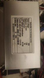
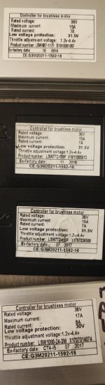
Some observations about LSW12G-USAMK-F
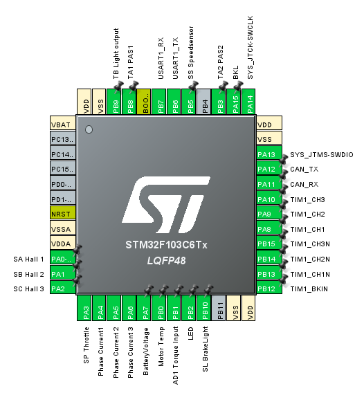
Raw temperature sensor data is on PB0 - adcData[5]
Analog temperature sensor pin is pulled up to 3.3v using 3000ohm resistor
Digital SS1 pin is pulled up to 3.3v using 9300ohm resistor (or close to it according to my measurements)

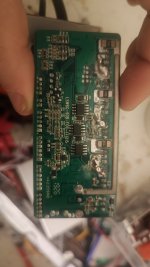
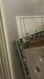
Below is the picture of traces below the MCU if anyone needs to follow vias.

traces.jpg
PXL_20221029_063729975.jpg
PXL_20221105_071923743.jpg
PXL_20221105_072416874.jpg

A good point to connect additional pull-up resistor is below, it is at 3.3v

(edit)
Updated 3.3v pull-up picture with correct VDDA location

vdda.png
Connecting SS1 to TEMP_SENSOR (PB0) to 220ohm resistor with pull-up to this point gets ADC close to 200ohm of total pull-up across 2 joined pins, with acceptable range to drive both the digital and analog pins together.
 
dls said:
with acceptable range to drive both the digital and analog pins together.

Great work! So you will wire the signal to PB0 and PB8 in parallel?

Pinout%20New%20Generation.PNG


regards
stancecoke
 
Yes, that's the plan, but it is motor hall sensor, not PAS hall sensor. I have not ran autodetect yet - I have been monitoring raw ADC values on stationary wheel off the bike in debug display mode, rotating the wheel by hand. I've also tested a few values with a 10k potentiometer and I am also getting what I would expect from ADC.

Pull-up resistor connects 3.3v point to PB0 pin on the board. Wires from PB5 and PB0 exit the controller separately and are connected at motor breakout connector. This allows me to run it in multiplexed mode with my current motor, which has a single white wire in Z9 connector, but in case I upgrade the motor to a model with L1019, I can split the external wires and connect them to separate temperature and speed sensor lines on L1019 connector. I am planning to pot the controllers with thermally conductive potting epoxy, so anything that is on controller board itself will not be accessible. I am also planning to replace the SMD LED with through hole LED and expose it through the case - in case I want to add some error codes through led in future.

Code will need slight adjustments - my NTC thermistor has a different Beta than what's in code and I need to filter out ADC values below 100 to prevent hall sensor events from affecting the temperature reading.

Word of caution - don't move the resistor lead after soldering it to capacitor, ceramic capacitors are very gentle. Luckily I've had some spare 0805 100nF caps - I was able to replace the one I damaged.

pull-up220r.png
temp-sensor-retrofit.png

What are the units for PH_CURRENT_MAX variable? How is that converted to amps?
Similar question for TS_COEFF and battery voltage/bar thresholds, how is that converted to human readable units?
 
dls said:
What are the units for PH_CURRENT_MAX variable?
It's not described in the wiki precisely yet. :wink:
ADC value * calibration factor = current in mA (where the calibration factor is without the shift factors)

Example: an ACD-reading of 100 for phase current is

100*38 = 3800mA

Same principle for battery voltage.

For TS_COEFF I never thougt about physical units, I just adjust it by trial and error to give satisfying motor power in relation to my pedaling power. It depends on the used UART protocol also, as some protocols transmit the assist level from 1...5 others from 0...255

regards
stancecoke
 
Thanks. It is still not very clear where is the calibration factor coming from.

It also looks like the T_NTC is using Beta 3900. How is Beta represented in this line?
I am not really sure I understand where the integers are coming from. Are these bit-shifted Steinhart-Hart model coefficients?
 
Hi, everyone! :) This is my first post in this forum. My colleague Andreas pointed me to this thread so I might explain. I was asked to devise a way to determine the temperature from the NTC resistance value without using floating point operations and those lines of code were the result.

This algorithm takes advantage of the fact that the shift operator behaves exponentially. First I determine how many binary digits the resistance in ohms has (minus 1). Then I shift that number (called n) 6 digits to the left so the logarithmic base becomes ε=2^(1/64) and divide the resistance value (after shifting it to the left by 13 digits to increase accuracy and make the following iteration terminate) by approximately ε by subtracting 11/1024 of the current value iteratively until it has one binary digit less, each time incrementing n. The estimated value of the binary logarithm of the resistance in ohms is then n/64-1/128, so the measured temperature β/(ln(R/10kΩ) + β/298.15K) can be estimated as 64/ln(2)*β/(n-1/2 + 64/ln(2)*(β/298.15K - ln(10000))) and the temperature in °C times 6 (because 0.15 is close to 1/6) as 2160580/(n+357)-1639 accordingly, assuming β=3900 K, as 6*64/ln(2)*3900 ~ 2160580.09, 64/ln(2)*(3900/298.15 - ln(10000))-1/2 ~ 356.86, and 273.15*6 = 1638.9. So that is where the integers come from.
 
Hi Hendrik. Thank you very much for the detailed explanation.

With the help of this explanation I was able to parametrize Beta value


It also does not help running controller without attached accessories. The 3.3v point I previously used was connected to PA3.
I've traced VDDA trace to three caps on the back of the board and updated the post above with corrected points.

Tuning R_TEMP_PULLUP:
Resistor tolerance is usually 1% or 5%. Use a 1% 10k resistor connected between Temperature Sensor wire and GND to fine tune R_TEMP_PULLUP value. It should read 25C (second integer in debug mode). Increase R_TEMP_PULLUP if it reads high. Decrease it if temperature reads low. Once you get 25C with 1% 10k resistor, it is calibrated to within 1%. In my case with 5% 220ohm resistor reading 220.3 and PB0 connected to PB8 I had to set R_TEMP_PULLUP to 212. NTC Beta is irrelevant at 25C/10kohms.

Temperature detection works with motor speed multiplexed on the same wire. Thank you very much for your help, stancecoke and Hendrik. I have a commit in my fork, which allows for multiplexed operation without speed affecting temperature reading. I may be adding IIR filter to smooth out NTC signal, as it is rapidly fluctuating +/-2C.
 
I finally got a chance to test it out on a bike. Auto-detection worked. Temperature is correctly detected, and so is speed. I've had to increase ADC cutoff to 200 to avoid false positives.

When the Speed Sensor is pulled down, other ADC signals seem to shift by 3-5 ADC units, likely due to 220ohm resistor being too strong for existing 3.3v rail powered by LM1117. I may add a cheap buck converter - linear regulator chain to create a separate 3.3v rail just for the speed/temperature sensors, because I suspect the current sensing ADC values may also be slightly disturbed by speed sensor on 220Ohm pull-up.

It seems that sometimes the motor is spinning in reverse after stop. Is this normal? My motor is geared with clutch, so there is no real usability issue with this, but it did seem odd.

Is there a way to allow controlling motor current from both the torque sensor and thumb throttle, but without having to have PAS signal present, as in pedals not turning, taking off in traffic using thumb throttle? Is there a #define for that, or does this require code change?

For voltage multiplier, should the ADC * multiplier result in millivolts or 0.1 millivolts?

What is the correct way to calibrate current? My controller came with 1mOhm shunts. Should I be able to use values in repository if I replace shunts with 2mOhm type?

When switching from 6-step to FOC, there is a significant increase in torque. Is this because my controller current is not calibrated, or is this expected behavior?
 
Thank you for your feedback, nice to hear, that you got it working!

dls said:
It seems that sometimes the motor is spinning in reverse after stop.
You have to set the regen current to zero, Otherwise the motor can accidently spin up in reverse in the freewheel, if you pull the brake lever.

dls said:
Is there a way to allow controlling motor current from both the torque sensor and thumb throttle
we had a similar topic in the german forum today. The solution how to have throttle override in TS-mode is described here. Please use a translator.

If you want both, torque override and throttle override, a little more changes in the code are necessary.

dls said:
For voltage multiplier, should the ADC * multiplier result in millivolts
the result is in mV. I was confused myself yesterday. The relevant factor is stored in the CAL_V constant. CAL_BAT_V is only used for the SOC-bar calculation in the Kunteng Display...

regards
stancecoke
 
Thanks! I see you've made some changes for torque offset and brake light pin for HimiwayCobra. Are you planning on merging these changes into mainline branch (excluding pin reassignments for clone board)?
 
dls said:
Are you planning on merging these changes into mainline branch
No, not at the moment, but you can copy them easily to the master by yourself, if you like them... :wink:

regards
stancecoke
 
Yes, I also need the override for my set up and I really like 1b7db04 since it makes code a lot more readable, but I did not want to have merge conflicts - cherry picking is not possible since torque override is the same commit with pin re-assignments :). I'll probably just spin up a separate branch to be able to merge from upstream without merge conflicts if you end up pushing these changes to mainline.
 
Hello guy's. I want to try the firmware through display port but I don't see any option for UART or to choose com port in the app. Attaching pictures of my controller.
 

Attachments

  • IMG_20230117_212454.jpg
    IMG_20230117_212454.jpg
    2.1 MB · Views: 209
  • IMG_20230117_213301.jpg
    IMG_20230117_213301.jpg
    2 MB · Views: 208
  • IMG_20230117_212517.jpg
    IMG_20230117_212517.jpg
    2.4 MB · Views: 207
To flash via the display connector, you have to use the github action feature. If you commit your changes in your fork, the firmware is build automatically and you can download the .lsh file in the artifact file.
To flash the lsh file, you have to use the original Lishui firmware update tool.
You can use any USB-UART converter for flashing.

index.php


regards
stancecoke
 
Ok thank you. That's a little step forward but I don't think I'm capable of this :lol: maybe someone can share .ish file for some basic settings and kunteng or bafang display to see if I can flash it? Or it maybe easier for me to flash on the programming pins? But I don't think my controller has them
 
honya96 said:
Can you help?
the STM command line tool (comes with the STM32Utility) is not installed, or the path to it is not correct...

regards
stancecoke
 
stancecoke said:
honya96 said:
Can you help?
the STM command line tool (comes with the STM32Utility) is not installed, or the path to it is not correct...

regards
stancecoke

So I was able to flash by stlink after a lot of struggle.

I can write a more detailed "how to" for non-programers if you want.

But now the controller red led is flashing fast. Do you have implemented any fault codes on display?

If you help me get it running I can send you a free controller. I can get around 20 for very cheap. Leftovers from bike manufacturer.

Btw after flashing by stlink I'm still not able to flash by display connector. IMG_20230207_220734.jpg

Thank you
 
honya96 said:
I can write a more detailed "how to" for non-programers if you want.

Nice to hear, that you were successful in the end! Of course feel free to improve the wiki, anyone with a github account has write access to the wiki.

https://github.com/EBiCS/EBiCS_Firmware/wiki

honya96 said:
Btw after flashing by stlink I'm still not able to flash by display connector.
You have to flash back the bootloader with the STLink to use the display connector.
New controllers should have the bootloader installed by default.

regards
stancecoke
 
I don't know if you understood, I flashed successfuly but it's not working. Red led Is flashing faster than normal as some fault and it's not doing anything, I set auto identify debug option and the motor doesn't start.

Is the bootloader needed for it to run? Can you give a little hint how to flash it. I didn't look into it yet, maybe I can figure it out and add to wiki
 
honya96 said:
Red led Is flashing faster than normal as some fault and it's not doing anything, I set auto identify debug option and the motor doesn't start.
the flashing red led only indicates, that the main loop is alive.
After flashing, you have to start the autodetect routine first. The easiest way is to set and the display type to debug and activate the autodetect flag in the config.h. Then the routine runs at every start of the system. After runnig it once you can flash again with the autodetect flag disabled. If you attach a USB-UART converter to the diplay port, you can see the debug data, sent from the controller.

honya96 said:
Is the bootloader needed for it to run?
no, if you flash by the STLink, the bootloader is not needed.

regards
stancecoke
 
Back
Top