
You are using an out of date browser. It may not display this or other websites correctly.
You should upgrade or use an alternative browser.
You should upgrade or use an alternative browser.
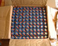
New pack, look what the postman brought!
- Thread starter maxwell
- Start date
Sweeet!!! what brand are those ?
And can you describe the process to measure internal resistance if it's not toooo complicated ?
And can you describe the process to measure internal resistance if it's not toooo complicated ?
Brand, noname chinese.
Measuring internal reisitance...
Measure open circuit voltage,
Connect 'scope on AC across terminals,
Briefly apply a resistor (I used 4.7 ohms, near enough an amp) across the cell,
Note the change in voltage on the 'scope screen,
Do some sums.
Internal resitance = (resistor applied) * delta volts (from 'scope) / open circuit voltage.
One measurment in my case, open circuit volts = 3.81, delta volts 40mV.
4.7*0.04/3.81 = 49.34mOhm
I used an oscilloscope because measuring the delta volts with a voltmeter is almost impossible.
xyster
10 MW
And can you describe the BMS again?
The BMS,
Each twin pack has a low voltage trip, sends a signal to the main circuit breaker opening it. I have set this to 2.7V, fine for individualy monitored cells (well 4 parallel ones).
Also on board I have the cell balancers, the reference chain of resistors is always connected, however the op amps are only connected when charging, they take 2mA which would flatten the pack in 6 months, the low voltage trip only takes 20 microamps or so, good for 55 years!
knightmb
100 kW

xyster
10 MW
knightmb said:
Maxwell needs more cells! 8p is only good for about 20-25 amps....
I'm still curious about your BMS.
Do you have a schematic for it?
I have a big pile of used panasonic cells, but the BMS they came with is useless, since it's only rated for 1 amp and I can't seem to reverse engineer the charge controlling part (I think part of the circuit is off board).
These cells are a few years old and were abused, so I don't think they have much life left.
Looks like a big stack of fire-crackers!!!!! hint hint !! 
xyster
10 MW
maxwell said:Cells rated at 2.2Ah and 1.5C = 8x1.5*2.2 = 26.4A
1. The specs seem optimistic for multi-cell packs that always have at least some imbalance while in use. After cooking a few, I went to 15p from 12p for use at 35 amps. Mine are spec'd 1.5C too.
2. Cell resistance rises over time, lowering that rate.
http://www.batteryuniversity.com/parttwo-31.htm
Lithium-ion has a slightly higher internal resistance than nickel-based batteries. The cobalt system tends to increase the internal resistance as part of aging whereas the manganese (spinel) maintains the resistance throughout its life but loses capacity through chemical reaction. Cobalt and manganese are used for the positive electrodes.
High internal resistance will eventually render the battery useless. The energy may still be present but can no longer be delivered. This condition is permanent and cannot be reversed with cycling. Cool storage at a partial state-of-charged (40%) retards the aging process.
Yes I know I am optimistic, but 20A would give me over 1kW, oops I forgot I am limited to 250W (motor output).
Even then I could devise a program for the controller that would try and give me 250W out, a constant power throttle maxed at 250W. I could still climb a 1 in 10 at 8MPH no pedaling. That should lead to a reasonable performance, then to be legal I would have to limit the top speed to 15.5MPH (25kph) to remain so.
I would have to have two modes, one legal for road use and one full power for off road use, never to be used on the road of course. It would have to default to the legal mode in case I am stopped by the fuzz or forget to switch over to road mode(!)
OK it may only be used if I get pulled (titter titter).
Because I have two packs when a cell goes lame only one pack would trip, then I can find the naughty one and replace it, having only 4 in parallel makes this a lot easier (and the trip more likely). Thats why I have spent a bit of time designing the BMS.
I must admire your bravery Xyster running all those cells in series without a BMS in a wooden box near your crown jewels! Mine are next to my back and in an aluminium box, not worried a bit (tremble tremble). Only time will tell.
I must admire your bravery Xyster running all those cells in series without a BMS in a wooden box near your crown jewels! Mine are next to my back and in an aluminium box, not worried a bit (tremble tremble). Only time will tell.
xyster
10 MW
maxwell said:Because I have two packs when a cell goes lame only one pack would trip, then I can find the naughty one and replace it, having only 4 in parallel makes this a lot easier (and the trip more likely). Thats why I have spent a bit of time designing the BMS.
You know electronics better than me to design a BMS from scratch.
There's a lot of variance with the PTCs on these that may be a consideration too. When I ruptured a couple from overdischarge (I was just below 3.7v/cell open-circuit voltage and pulling 35 amps from 12-cells in parallel when it happened), it seemed the PTCs caused a cascade failure throughout two parallel subpacks by some cutting out their cells earlier than others, increasing the load on the remaining cells. Perhaps your BMS can prevent this from happening. Regardless, there's very little capacity left below 3.7v resting voltage, and that very little capacity dumps very quickly, leading to overdischarge occuring very easily. So I'd suggest a 3.7v cut-off voltage even if that sounds a little high compared to the specs for single cells.
I must admire your bravery Xyster running all those cells in series without a BMS in a wooden box near your crown jewels!
I have no interest in fathering children; those "jewels" just kind of hang around, doing nothing much for me anyway...
I'll be watching your results closely, especially as I'm interested in doing the 60-amp controller mod w/variable current limit. If it's safe, I'd love to squeeze another 5 amps from my 18650s for 40 amps total, then add a 6s boost pack of emoli's or A123's on a relay for 96 volts. 4000 watts ought to get me up some of the hills around here much better than my present 2500 watts, which is kind of marginal with my hubmotor for sprightly climbing steep (>15%) inclines. I'm also hesitant to change a system otherwise working so well.Mine are next to my back and in an aluminium box, not worried a bit (tremble tremble). Only time will tell.
Xyster,
The BMS will prevent the cascade going out of control by tripping out at 2.7V, this will probably happen under load stopping any overdischarge. I think you may have even reverse polarised a cell or two during the event.
I too have no interest in fathering children, but I have fun with my jewels neverthless. Anyway loosing them without aneasthestic must hurt loads.
Cool, thanks Maxwell.
That's a lot of parts.
I see how most of it works, I like the FET switch to turn off the op amps when not charging.
What are the 'chain high and chain low' points?
Where does the reference voltage come from? (I didn't look up any of the part numbers).
That's a lot of parts.
I see how most of it works, I like the FET switch to turn off the op amps when not charging.
What are the 'chain high and chain low' points?
Where does the reference voltage come from? (I didn't look up any of the part numbers).
Quite a lot of parts, and I have to make 14 of them but quite cheap compared with 'real' BMS chips and I can have as many as I like in series with tthe right voltage low trip FETs
The chain high and low are series connected to the other BMSs' with the top and bottom going to the pack end terminals, giving reference points for the balancing.
The low trip reference is in the TLV3012 chip, 1.242V, it takes a few tenths of a microamp!
All this connects to the trip board, the coil refers to the release coil in the breaker, there is a big external capacitor to ensure a trip if a dead short is applied.
Similar threads
- Replies
- 22
- Views
- 1,735
- Replies
- 164
- Views
- 2,836
- Replies
- 25
- Views
- 2,975
- Replies
- 26
- Views
- 801