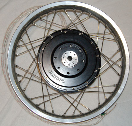
The Variable Field Brushless Motor thread

Doctorbass

100 GW
Joined
Apr 8, 2007
Messages
7,496
Location
Quebec, Canada East
Remember this great video ? :mrgreen:


Ashiya University Solar Car Project Sky Ace TIGA variable field magnet motor plot type 可変界磁モーター

[youtube]6_41btVawMc[/youtube]

I finally found their WEBSITE !! http://www.ashiya-u.ac.jp/solarcar/

Alot of us saw it and was impressed by the variable rotor position from the stator that increase speed.

The motor can controll RPM by controller, also by variable field magnet.

In case RPM is controlled by the controller it self, under the 100% which will have switching loss.
However speed controll by the variable field magnet controlling which does not have any loss even low RPM as controller is alwas 100%.
Because the speed is controlled by variable field magnet.

The known specs are:
MODEL: M15150D ( specially designed for the Sky Ace TIGA Team)
DC brush less variable field magnet in wheel DD [Mitsuba] make
Rating: 2kW (Max 7kW)
Max speed with 140kg solar car: 152kph
Built in July 2000


From now we did motor tuning like Delta-wye, serie parallel and over amp and over volt.. but none of us tried that!!! :wink:

I would be very curious if someone of us could do that.. including me.. :wink:


About the famous video, we know it's a motor that was designed for solar race. It's from the TIGA MITSUBA race team. A chinese or japanese team.

The variable field motor seem made by the Mitsuba company..

I found more video about variable field motor! when searching from their youtube account.

I thought it could be interesting to see if it could be applied to the RC motor many of us like or to our hub motor.

Some video ( some are availlable in HD)

Variable rotor stator alignment on Mitsuba motor (Expt 1)
[youtube]x6u-GebOfRQ[/youtube]

Variable rotor stator alignment on Mitsuba motor (Expt 2)
[youtube]ovtjlJGCo1Y[/youtube]

Variable rotor stator alignment on Mitsuba motor (Expt 3)
[youtube]HiD6amSoVsg[/youtube]

DQB TJSS I
[youtube]YaIwTTpztaI[/youtube]


Venture II Engine Test 2
[youtube]SA7cXzEVW0I[/youtube]


Venture II Engine Test
[youtube]jUrSaKDLI4k[/youtube]


The Solar Car Racing Motor of Mitsuba M2096 2009 ver Video 2
[youtube]V-eoEHjc65w[/youtube]

The channel of mnmsmushy:
http://www.youtube.com/user/mnmsmushy#p/u/9/HiD6amSoVsg

The channel of ngjyang86
http://www.youtube.com/watch?v=ovtjlJGCo1Y&feature=related

The channel of nomnom13's
http://www.youtube.com/user/nomnom13#p/u/4/zLc2nYs7SKw


Now something quite different: Russian ultra efficient magnet motor
[youtube]L1rilJFviVM[/youtube]

Doc
 
The Mitsuba motors

http://www.mitsuba.co.jp/scr/01solar_m2096d.html

they say 96% efficiency and up to 5kW for 11kg

m2096.jpg


Some other interesting products here:
http://babelfish.yahoo.com/translat...lar_m2096dll.html&lp=zh_en&btnTrUrl=Translate


study_commuter01.jpg

study_commuter02.jpg

study_commuter03.jpg

study_commuter02.jpg


http://www.mitsuba.co.jp/images/scr/m1048/m1048r.jpg


study_acg01.JPG


Doc
 
One thing they don't mention is the efficiency when the field is shifted. If you only have 50% of the stator covered by magnets, the other half if just adding heat and not power to the motor.
 
I'm so glad you started a thread for this motor. I spotted it in your youtube favorites whilst browsing your channel. I love the desing, it is the sex and if there ever was a motor I would like to see replicated here at the sphere the V-field here is the one. Though it does take the simple electric motor and complicate it quite a bit I think the advantages would be well worth it. I believe they had a scooter they made with a version of this motor, or maybe it was just the same company. the scooter was called "sumo" and had quite a resemblance to kanedas bike from akira.
 
I found curious to see this motor desing... Quite similar to the MH603 from Markcycle

study_commuter02.jpg


1.jpg

Doc
 
For sure it is pretty hard to pull the stator out of the rotor while it is running. They will have some hot spots on the outer corner of the magnets they won't like too much. I also wonder how the torque curve would look like. Wouldn't make sense if the motor could turn faster but doesn't create enough torque to accelerate :lol:

On a RC outrunner I had done this unvoluntarily. The prop pulled apart stator/rotor a few millimeters and I found out this was a selfregulating process. I guess it was running on highest efficiency this way ( at least it was the highest possible RPM with this winding/prop combo)
In a bikes hub this could be done with centrifugal force like in a scooters CVT...

Olaf
 
I was thinking about this a while back when I first saw the first posted video.

Rather than sliding the stator out, I was wondering if you could make the magnets move away from the stator radially. Mount the magnets on some sort of spring-like assembly. So that the faster the wheel was turning, the further away the magnets got from the stator - thus weakening the field. The tough part would be to make the magnets move uniformly - maybe some sort of spring-loaded iris setup.
 
I think that this torque vs speed ration is somewere like fo rthe delta wye.. more torque less speed.. and vice versa... same power...

I found a patent about that variable field motor:

Brushless permanent magnet motor with variable axial rotor/stator alignment to increase speed

capability
http://www.freepatentsonline.com/6492753.html

Some interesting sumarry:

Conventional permanent magnet motors can apply high output torques up to an rpm limit called the base speed. The base speed rpm is governed by the phenomena of permanent magnet motors building up “back-emf” electrical potentials as rotational speeds increase. The back-emf is governed by the magnetic gap flux density, number of winding turns, and rotational speed. As the rotational speed of a permanent magnet motor increases, the back-emf will build up until it equals the supplied voltage. Once the back-emf equals the supplied voltage, permanent magnet motors will not operate any faster. This back-emf rpm limiting characteristic protects permanent magnet motors from the over speed damage that is common with series wound electrical motors used in vehicle applications. The back-emf base speed characteristic that protects permanent magnet motors also tends to limit the dynamic rpm range.

In order to accelerate from rest or from low speeds, many electric vehicles have a fixed reduction drive ratio that is set for high torque. While such configurations provide the necessary high torque to overcome inertia, it results in a low base speed and a limited top speed. In addition to a low speed, constant torque operation, it is desirable for many motor vehicles to also have an upper range of constant power, where speed can increase with decreased torque requirements.

There are methods by which to operate a brushless permanent magnet motor or other motor type beyond the base speed. These methods can be broadly classified as either those using electrical means or those using mechanical means.

Methods of electrically enhancing speed or varying magnet flux include high current switching of additional phase coils or switching the way the phase coils are connected. The costs of such contactors and their contact wear tend to negate the advantages of a high durability brushless motor. Supplemental flux weakening coils have also been used to reduce stator flux and increase speed. This latter approach typically requires contactors and increases heating effects in the stator. Other methods can achieve higher speed operation by varying the waveform shape and pulse angle of the applied driving current or voltage.

Other known methods include the use of DC/DC amplifier circuitry to boost the supply voltage in order to achieve a higher motor speed. This method increases system costs and decreases reliability and efficiency. Such electrical approaches to increasing a motor's base speed are exemplified in U.S. Pat. Nos. 5,677,605 to Cambier et al., 5,739,664 to Deng et al. and 4,546,293 to Peterson et al.


Another:
http://www.patentstorm.us/patents/6492753.html


One drawing
:
6555941-0-display.jpg
 
michaelplogue said:
I was thinking about this a while back when I first saw the first posted video.

Rather than sliding the stator out, I was wondering if you could make the magnets move away from the stator radially. Mount the magnets on some sort of spring-like assembly. So that the faster the wheel was turning, the further away the magnets got from the stator - thus weakening the field. The tough part would be to make the magnets move uniformly - maybe some sort of spring-loaded iris setup.

Ah ha.. centrifugial force.. .. Great idea..

I found the patent about that:

U.S. Pat. No. 6,194,802 to Rao discloses a pancake type motor that uses a fixed axial air gap. In this type of motor the axial gap is functionally equivalent to the radial gap in an internal cylindrical rotor motor design with a radial air gap. The individual magnet sectors in the rotor are mounted on spring loaded radial tracks. When the rotor rpm increases, centrifugal force causes the magnet sectors to extend radially, reducing the active area of magnet aligned with the stator coil and reducing the back-emf. This causes the motor to run faster than the base speed. Rao is similar to Masuzawa et al. and Holden et al. mentioned above in the centrifugal method of activation. The design of Rao requires extensive machining of the radial magnet tracks which increases costs and adds to the complexity. In addition, maintaining a sufficient level of balance of this magnet rotor is complicated by several factors. Even after the rotor is balanced with the magnets at their inboard position, as speed increases the position of the individual magnets is affected by difference in mass of the magnets, spring constants/rates, and sliding friction of the magnets along the tracks. Small variations in the resultant in the individual magnet positions would have a disastrous effect on the balance at high rotor speeds. These factors would necessarily adversely effect the ability to reduce back-emf of the motor and operate above the base speed.

Doc#
 
Doctorbass said:
I think that this torque vs speed ration is somewere like for the delta wye.. more torque less speed.. and vice versa... same power...


It would not work the same as just a wind or termination switch. Let us assume we have a 30mm wide stator. If the stator/magnet overlap is changed to 50%, we would have the speed of a 15mm wide stator, the copper losses of a 30mm wide stator, and only the power of a 15mm wide stator. If the battery and motor is big enough to handle these losses, then the system may be effective enough to use. I would rather have a two speed gearbox however.


There may be much larger losses in the wire without magnet coverage as well, but I do not have a simulator to see how the localized amp draw is affected (if at all).
 
Of course, another option would be to have a combined brushed and brushless motor - without regular magnets.

Two sets of coils - the standard inner brushless stator, and then use electromagnets on the outside (brushed) instead of standard ones, where you can increase or decrease the outer field as needed. Of course you'll be using more electricity.........
 
johnrobholmes said:
Doctorbass said:
I think that this torque vs speed ration is somewere like for the delta wye.. more torque less speed.. and vice versa... same power...


It would not work the same as just a wind or termination switch. Let us assume we have a 30mm wide stator. If the stator/magnet overlap is changed to 50%, we would have the speed of a 15mm wide stator, the copper losses of a 30mm wide stator, and only the power of a 15mm wide stator. If the battery and motor is big enough to handle these losses, then the system may be effective enough to use. I would rather have a two speed gearbox however.


There may be much larger losses in the wire without magnet coverage as well, but I do not have a simulator to see how the localized amp draw is affected (if at all).

I know what you mean.. I think you say that the resistive part of the coil is not the same when the coil part that is normally all exposed to intense magnetic fieldis placed away from the magnets.. so the coul become one part with line fulx and the other part have less of these line .. so the inductive and resistive portion isn't the same, creating loss... That make sense..

Have you watched these video i posted above? Variable rotor stator alignment on Mitsuba motor (Expt 1, 2 and 3)

They are testing the power consumtion in no load setup with different stator /rotor offset for the same speed.. it's interesting.

Doc
 
I have watched the vids showing it, but have not watched them all or payed attention to the no load wattage. I approached a few motor engineers about two years ago with reference to the design, and the response was not very favorable in relation to the efficiency.
 
Seen here:
http://en.wikipedia.org/wiki/Owen_Magnetic
The Owen Magnetic was a brand of luxury automobile manufactured between 1915 and 1922, and was notable for its use of an electromagnetic transmission. The manufacture of the car was sponsored by R.M. Owen & Company of New York, New York. The car was built in New York City in 1915, Cleveland, Ohio between 1916 and 1919 and finally in Wilkes-Barre, Pennsylvania in 1920 and 1921.

While the cars were powered by a six-cylinder engine, power for the wheels was based upon the same electromagnetic principle that turned the propeller of the U.S.S. Battleship New Mexico.

Automobile author Henry B. Lent described the drive mechanism thus:

The drive mechanism had no direct connection between the engine and the rear wheels. Instead of a flywheel, a generator and a horseshoe shaped magnet were attached to the rear of the engine's crank shaft. On the forward end of the car's drive shaft, was an electric motor with an armature fitted into an air space inside the whirling magnet. Electrical current, transmitted by the engine's generator and magnet attached to the armature of the electrical motor, providing the energy to turn the drive shaft and propel the engine's rear wheels. Speed for the car was controlled by a small lever adjacent to the steering wheel.
The first Owen Magnetic was introduced at the 1915 New York auto show when Justus B. Entz's electric transmission was fitted to the Owen automobile. Walter C. Baker, of Cleveland Ohio, owned the patents on the Entz transmission thus each of the 250 Owen Magnetic automobile produced in New York were built under license.

The car became as famous as the company's clientele which included Enrico Caruso and John McCormack. Owen Magnetics were advertised as "The Car of a Thousand Speeds"

In December 1915, the concern was moved to Cleveland when the R.M. Owen Company joined Walter Baker (of Baker Motor Vehicle) and the Rauch and Lang concern. The Baker Electric Car company would produce the car, Rauch and Lang would build the coachwork. Because of the combined resources, the 1916 Owen Magnetic increased its model range for 1916 model year, with prices in the $3,000 to $6,000 dollar range. Production continued through 1918 when Baker shifted its focus to War goods manufacturing.

The company reorganized as the Owen Magnetic Motor Car Company of Wilkes-Barre Pennsylvania and resumed production, this time with an order for 500 vehicles from Crown Limited of Great Britain. Under the terms of the agreement, the cars were named Crown Magnetic, however before the order could be fulfilled, Owen Magnetic filed for receivership.

The Woods Dual Power car manufactured by the Woods Motor Company in Chicago also used the Entz transmission. The Woods car was similar in many ways to today’s hybrids. It used both a gasoline engine and electric motors to propel the wheels and utilized braking to recharge the batteries.

Not sure if there's anything to be gained by having a "two-stage" system w/motor at constant rpms then a separate "lossy"(?) electric transmission but just thought I'd throw this in here.
Tks
Lock
 
Id always wanted a way to have a nice reliable DD hub motor with some sort of option to move the magnets away to enable you to ride home easily when the batteries die or the system fails. The drag on my conhis was pretty bad. But I hadnt realised about all this stuff.

If you pause this video at about 38 seconds it shows a conical designed motor. If you set a hub motors magnets at an angle and had the stator move left to right slightly Id guess this would switch between very high torque and then high speed. Seems more simple and accurate than trying to move magnets centrifugally outwards and wouldnt need extra space diameter wise. Damn I wish I had a machine shop lol.

[youtube]Mcl6vI755YQ[/youtube]
 
Back
Top