shortcircuit911
1 kW
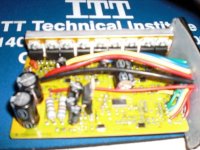
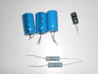
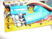
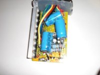
Hello all, I have a set up from e-bikekit.com, and want to make some modifications to it. I have already done a shunt mod to it, and am currently running it at 48v. I would like to run it at 60 or even 72v, but I think I will blow some of the circuitry. Can anyone tell me what size caps, mosfets, or anything else I might need in order to be able to run 60v+. Any advice would be much appreciated.