Well I finally got it all together. I re-flashed the MCU and set the amps to 50A.
This unit came with a precision R12 mod from Keywin so double the software values for LVC and Regen.
I set the software LVC to 18.8V which is a real LVC = 2 x 18.8V = 37.6V.
I set the software Regen to 75V which is a real Regen = 2 x 75V = 150V.
I added the PowerPole connectors and an extra e-Brake connector.
*

Here is a screen shot of the software flash settings.
*

The ignition voltage regulator circuit modifications are shown here.
Note the thermal switch on the mosfet. The switch opens at 100 degrees Celcius.
Also note the FJP9100 high voltage transistor mod. The transistor mod is real simple.
*

A close up shot of the transistor mod.
The transistor drops the voltage down to the on-board switching circuit.
The switching circuit really isn't designed (by XieChang) to take 150 volts.
The transistor mod makes for a much longer safer controller life.
*
View attachment 4
Real simple to build.
*

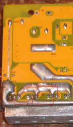
And the bottom of the board.
*

I added a PVC sheet for electrical insulation but cut an area out for the resistors to shed heat.
*

When the
LEFT e-Brake alone is slightly pulled (BK to GND is shorted) the throttle will allow variable regen.
When the
RIGHT e-Brake alone is slightly pulled (EBS to GND is shorted) the controller shuts off.
When
BOTH e-Brakes are applied the controller applies max regen to a stop.
*
So I guess it's time to start selling these things. I'll add a CA connector on the next unit.
Also very easy to change the LVC if needed.
Bad-Ass testers are welcome. I'll post in the "For Sale" section next.
-Knuckles