
Because there's a limit on the current available? Often the problem is with start-up, only.John500 said:If there is no torque advantage of Star over Delta, why to industrial applications favour Star for hi torque loads?
Thanks;
You are using an out of date browser. It may not display this or other websites correctly.
You should upgrade or use an alternative browser.
You should upgrade or use an alternative browser.
e-Buggy: Alternator Conversion
- Thread starter widodo
- Start date
Harold in CR
100 kW
I don't know much about this Alt-motor, but, This statement "Often the problem is with start-up, only." seems to be very common in many threads. Seems one has to get the Bike moving, then supply the motor voltage. Kinda like the old Whizzer gas Bikes. ???
I only meant it in relation to the industrial question.Harold in CR said:I don't know much about this Alt-motor, but, This statement "Often the problem is with start-up, only." seems to be very common in many threads. Seems one has to get the Bike moving, then supply the motor voltage. Kinda like the old Whizzer gas Bikes. ???
For us, this mostly relates to sensor-less controllers, no?
Harold in CR
100 kW
I read several different threads on different forums, so, I could be confused. Usually am, most of the time. 
Still, someone is playing with a Alt-motor, and having problems getting it to start. When I get back to read that particular thread, I might figure out what that problem relates to. Could be sensorless, but, I'm thinking Hall sensors and still it won't start, no load ???
Still, someone is playing with a Alt-motor, and having problems getting it to start. When I get back to read that particular thread, I might figure out what that problem relates to. Could be sensorless, but, I'm thinking Hall sensors and still it won't start, no load ???
dajsinjo said:here it is
http://www.youtube.com/watch?v=Qhr0bPiFxsE
That noise from your video is sooo familiar. I think you need a washer behind the fan to keep it from hitting the case?
dajsinjo said:widodo said:@dajsinjo: congratulation, seems the 200A controller works flawlessly, perhaps we should list down all the controller that has been proved to be working. Do you have any problem in starting it up ?, what is the lowest rotor supply for a reliable start up ?
I am still waiting for 200A controller
this one was 80A version of the same ( Mystery pentium 80 ) brought by my friend Zoltan
Isn't that 200A controller limited to 22V?
http://tinyurl.com/2ds5ncd
http://cgi.ebay.com/200A-Brushless-Motor-Speed-Controller-RC-Accessory-ESC-/150428455513?cmd=ViewItem&pt=Radio_Control_Parts_Accessories&hash=item23063c1259
dajsinjo
1 mW
John500 said:dajsinjo said:here it is
http://www.youtube.com/watch?v=Qhr0bPiFxsE
That noise from your video is sooo familiar. I think you need a washer behind the fan to keep it from hitting the case?
yes but it is so rusty ! It will take a lot of efort to unscrew it
dajsinjo
1 mW
John500 said:dajsinjo said:widodo said:@dajsinjo: congratulation, seems the 200A controller works flawlessly, perhaps we should list down all the controller that has been proved to be working. Do you have any problem in starting it up ?, what is the lowest rotor supply for a reliable start up ?
I am still waiting for 200A controller
this one was 80A version of the same ( Mystery pentium 80 ) brought by my friend Zoltan
Isn't that 200A controller limited to 22V?
http://tinyurl.com/2ds5ncd
http://cgi.ebay.com/200A-Brushless-Motor-Speed-Controller-RC-Accessory-ESC-/150428455513?cmd=ViewItem&pt=Radio_Control_Parts_Accessories&hash=item23063c1259
That is for the nominal voltage of Li-ion 3.7V
but it is higher than nominal when fully charged.
What I heard is that you shouldn't runn them over 30V
it worked with two lead acid in series on video
I wrap a rag around the fan and clamp the rag with vise grips. Then use an air impact wrench to rattle the nut off. Put a few drops of penetrating oil on the night before? NOT WD-40, real penetrating oil. 50-50 mix of Acetone and Automatic transmission fluid works better than most expensive P-oil. It does not store well, so just mix what you need in a glass bottle.
dajsinjo said:That is for the nominal voltage of Li-ion 3.7V
but it is higher than nominal when fully charged.
What I heard is that you shouldn't runn them over 30V
it worked with two lead acid in series on video
I think just to be save you could just cut down the ESC shrink-wrap, detach the heat-sink and confirmed the Type of FET used and search its maximum breakdown voltage.
Agreed with miles, we shouldn't create a confusion for newbies reading the forum so this is what I had found regrading to workable alter-motor:
1. Alter-motor, works with both SENSORLESS and SENSORED plain-low cost RC Controller, I personally try HK100A, Dajs try Mystery 80A sensorless controller. Still, they are challenge related for a reliable start up. I was manage to work around the issue by two things:
- a. Wired the stator as delta, which puts the stator supply requirement lower
- b. Puts max supply for rotor (mine is at 4V), and decrease it after startup for higer RPM. I found it was easier to just used a Brushed Controller to provides a dynamic rotor supply but Dajs demonstrated that you could just simply use a rheostat
Still both star and delta configuration are viable for a sensorless controller, however given the same stator supply voltage (i.e. battery voltage) Star requires higher rotor supply for a reliable startup. Please correct me If I am wrong, but I believe this has got to do with the start up logic of a sensorless controller: The Controller will start the motor with some arbitary sequence for a determine period and expect the BEMF to shows for further commutation cycle, if the Rotor supply (hence the Flux) is not big enough, there won't be sufficient BEMF for controller feed back. Being a very low KV motor, we should assured that the BEMF is there even at a very low RPM. After that, the "field-weakening"/the ability to have a dynamic torque by varying the rotor supply is yours..
 . I had personally able to run the alter-motor as low as 70 RPM with a sensorless while then still reaching a top speed of 6000+ rpm
2. The Torque is HUGE, but you still have to remember that the rotor mass is relatively big, so if you plan for a sensorless, you need to assure that the starting from a stand still, the controller arbitrary cycle must covers those plus your gearing must be designed that to covers this as well (I used 1:21 gearing ratio for my eBuggy). After it runs you wont have any problem anymore.
Previously, My eBuggy used a 80A Bosch alternator, Delta Wired, Sensorless mode. But on the work bench, I have a 35A ND alternator Start wired, Sensored Mode which start soooo smooth. This is why, I'm currently working to make the 80A Bosch a sensored one. This should be easier done than the ND one as the BOSCH is significantly bigger, so more space for my fat finger to works
zlotvor
100 µW
widodo said:dajsinjo said:That is for the nominal voltage of Li-ion 3.7V
but it is higher than nominal when fully charged.
What I heard is that you shouldn't runn them over 30V
it worked with two lead acid in series on video
I think just to be save you could just cut down the ESC shrink-wrap, detach the heat-sink and confirmed the Type of FET used and search its maximum breakdown voltage.
I already did it! Actually first thing I did is disassembling it.
Parts:
18x FDD8896 - 30V, 94A, 5.7mOhm, N-Channel PowerTrench®MOSFET
3x IR2101 driver IC
ATMEGA8 @16MHz
elco's @35V
7805 voltage regulator(max 37V input)
So it's clear that this thing can't go over 22-24 volts. I drive it with a dirty servo controller code quickly written in bascom and I'm not sure that it actually works with 100% power. I'm sure it's not optimized!
Z
Widodo;
I took my camera this morning, but only got one shot before the batteries were flat. Spare set of batteries were for wife's camera and did not fit.
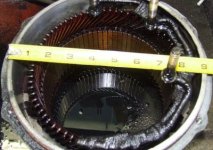
Overall length is 46cm. Weight @ 55KGs. Sorry for the imperial tape. Could not find metric tape this morning.
I took my camera this morning, but only got one shot before the batteries were flat. Spare set of batteries were for wife's camera and did not fit.
Overall length is 46cm. Weight @ 55KGs. Sorry for the imperial tape. Could not find metric tape this morning.
Attachments
John500 said:Widodo;
I took my camera this morning, but only got one shot before the batteries were flat. Spare set of batteries were for wife's camera and did not fit.
Overall length is 46cm. Weight @ 55KGs. Sorry for the imperial tape. Could not find metric tape this morning.
Wow
How much it will cost ?, is it available from the salvage yard ?
thanks for the extra effort John, really appreciate it.
zlotvor said:Parts:
18x FDD8896 - 30V, 94A, 5.7mOhm, N-Channel PowerTrench®MOSFET
3x IR2101 driver IC
ATMEGA8 @16MHz
elco's @35V
7805 voltage regulator(max 37V input)
So it's clear that this thing can't go over 22-24 volts. I drive it with a dirty servo controller code quickly written in bascom and I'm not sure that it actually works with 100% power. I'm sure it's not optimized!
Thanks for sharing Z, It provides me with the answer how those Hi Amps controller could be so cheap, Cheap AVR drove to the max in term of clock freq. with half bridge driver 2101. Most of ESC I had still using N&P Fets which might drove the price up. Further, Having a TTL compatible driver, it would also means you could just have additional FET banks for additional amps with Higher voltage then
By the way, did you mean that you just use Bascom's PulseOut command for wthe PWM servo controller ?. Because I did, and those cheap ESC were OK with the max pulse of 2 mS.
zlotvor
100 µW
widodo said:By the way, did you mean that you just use Bascom's PulseOut command for wthe PWM servo controller ?. Because I did, and those cheap ESC were OK with the max pulse of 2 mS.
Hi widodo,
If I remember correctly I was used CONFIG SERVOS command and after that just simply increment the servo(1) value. The code was really quick one and I forgot to save it
Fligh High
100 mW
John , sorry to tell you but that alternator has died . If they start leaking oil like that it's not worth repairing any more
But seriously it looks quite big , 9+ inch in diameter , are you sure it weighs 55 KILOS ?? That's hard to imagine... Are the stator-wires single thick strands of copper ? looks a bit like a denso sc , what are your plans with it ? Power-wise with the right controller you should be.....okay !(or pull a bike apart in two parts !)
> Widodo I have finally sort of decided what I am going to build electronic parts-wise it will be something like this : http://web.mit.edu/first/kart/controller_rev1.pdf because of its wide possibilities/freedom of design. April was hectic and tight money-wise but now I am almost ready to buy the parts. It's quite a list actually and a lot more work than I thought to compile a list of all the right parts / educate myself about them. Long time ago for me that I've done something with electronics it sucks if you just found out you have forgotten just 1 small part and can't continue ! (no electronics shops close where I live everything has to be ordered by mail). If I am at the building stages will open a new topic here at motor-conversions "Fligh High's alternator motor conversion experiments"
Maybe people will find it interesting....As I said before think this will be a good year for Alternator-conversions , hopefully we will all have some good and fun results !Because fun is what it's all about.Could you tell me something more about the micro-controller you are using (type) Atmel it was ? programmable in C ?(edit:already found Atmel AVRMega 8535) The home-made controller with hall-sensors is THE way to make an alternator work like it should I think.
Also how did you make the space for the hall-sensors in the stator? drill at an angle , dremel ? Because if you touch the copper wire ...... that's really bad
Also have you tried running your alternator with your made controller and the car-type battery already and with full power/revs , and do you want to use 12 or 24 volts on the buggy ? Or is the Fet-bridge/driver not yet up to it for trying to go to the max testing.
The stator I showed is junk and has been replaced. My camera batteries went dead so I did not get a picture of the repaired alternator, which was sitting beside it. I am just checking around for an inexpensive source of large alternators for other fellows. After I complete my current project of a conventional bike with hub motor, my second project will be a 4-5000W hubmotor in a motorcycle. By that time, altermotors will be well understood and a combination controller, which ramps down the voltage to the rotor as the PWM to the stator increases, will have been built, I HOPE!
Fligh High said:If I am at the building stages will open a new topic here at motor-conversions "Fligh High's alternator motor conversion experiments"
Could you tell me something more about the micro-controller you are using (type) Atmel it was ? programmable in C ?(edit:already found Atmel AVRMega 8535) The home-made controller with hall-sensors is THE way to make an alternator work like it should I think.
Also how did you make the space for the hall-sensors in the stator? drill at an angle , dremel ? Because if you touch the copper wire ...... that's really bad
Also have you tried running your alternator with your made controller and the car-type battery already and with full power/revs , and do you want to use 12 or 24 volts on the buggy ? Or is the Fet-bridge/driver not yet up to it for trying to go to the max testing.
I'm sure people will be interested in the tread, Please Do so, I'll help as far as I could.
Yes, I did used the 8535. Use INT0,1,2 to detect hal sensor level change, two of the interupt support level change but 1, only support the raising/failing edge, hence execute the CONFIG interrupt to change the toggling modes in every interupt to detect next edge. On every hal interrupt, the program will reads the hall values and use it up as an index for the commutation stage. Its a 8 bit data, which 3 bit MSB used for the high side control, and 3-bit LSB for the low side. If you will I could provides you with the commutation table. The low side are staticly drove by TTL, while the High side was PWM drived using timer1a&b, and timer2.
Its working ok, but with lack of high speed, hence need to enhance the logic such with sinusoidal PWM, but this mean I have to redisign it again as I was out of PWM driver already. For the future, I'm planning to use 74LS138 for decoding one PWM to the designated high side, and used the saved Timer to drove the Sinusoidal ramp. The 2101, works flawlessly, only accidental EMF spikes due to not properly connected cable to the brush had let one IC blow of and creating a shoot through in one of the phase, but the all N-channel FET arrangement works OK. I droved the sensored alter-motor with HK Car ESC in sensored mode and it works very well, hence confirmed that this is mostly due to not really sophisticated logic
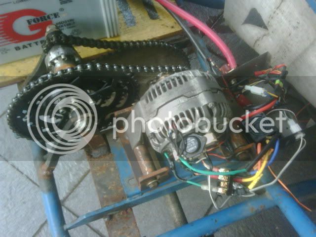
My ebuggy used 12V, but my ultimates goal is to used an Alter-motor to drove my 280GE front differential, John500 is helping me to look for 24-100A alternator, which will be driven by 48V supply 8) 8) .
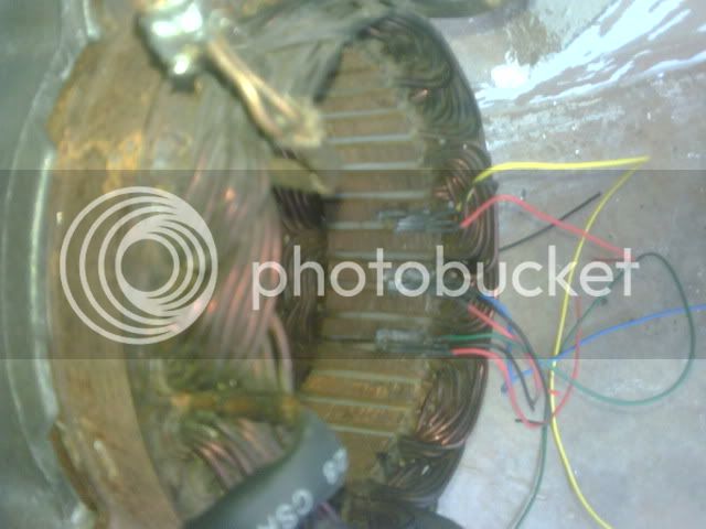
Anyway, been quite busy this weekend 8) with my stator (please forgive my BB's picture quality) :
1. Went to the machining shop, but before that marked the area which need to be removed with marker pen. Then drill them out. Its a 2 dollar jobs
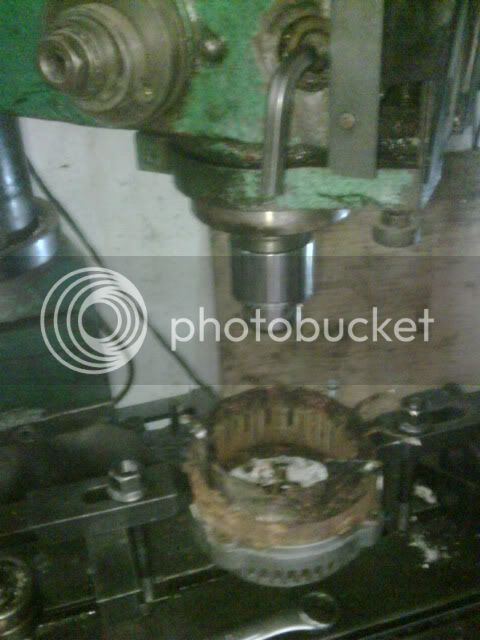
Please be really careful for the machine not to touch the stator wire, but 1-2 scratch wont kill you and easily insulated by thin CA.
2. the results then looks like this
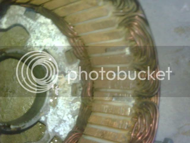
Please note that the sensor will be positioned just before the respective phase, and as the each phase interleaved with each other, on bosch/ND this would mean that each sensor will be separated by 1 tooth.
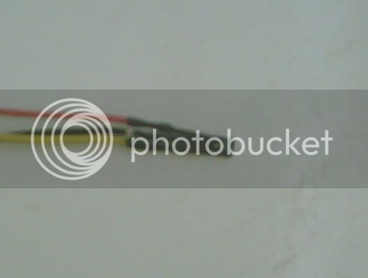
3. Wired up the hall sensor, previously I'm using the honeywell SS40A open collector, but hate the mess with the pull up resistor, hence currently I'm trying the totem-pole output of the SS411. Did have a problem previously with the pin assignment but it is turn out to be +, - , output.
Again, sorry for the picture quality. But I found Blackberry is the fastest medium for capture and share this project.
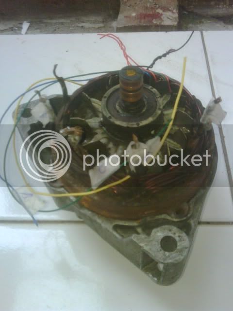
Please assure that all sensor was working before progressing further, as you will need to glue it up firmly to the stator. Found one which was not working after it has been glued, has been proved to be very frustrating.
The SS40 & SS411 was quite small, but as the space really tight, I removed its sides using a dremel, also rounded the edge a bit. Based on my experience it was OK to removed the BACKSIDE on the sensor a bit, but NOT the front side.
So far only able to wired 1 sensor before going out to the office, so will be continue later on.
Fligh High
100 mW
I just found out that the microcontroller I will be using is actually also based on the Atmel family products , it probably is slightly more advanced version than the one you have and also programmable in Basic (which I like !) Don't you find programming already difficult enough ? :? The three interrupt ports wil be very handy I see ! Also programmable in English thank goodness....not expensive 24 euro
C-CONTROL PRO UNIT MEGA 128 (Conrad Electronic)
110 K verfügbarer Flash-Speicher, 4 K SRAM + 60 k externes SRAM auf dem Evaluation Board Mega 128, 4 K EEPROM, 2 x UART, SPI, i²C, 10-Bit-ADC mit 8 Kanälen, Analog-Komparator, 5 PWM-DAC, 53 digitale I/Os, 3 externe Interrupts, 2 x 8-Bit-Timer, 2 x 16-Bit-Timer, Taktfrequenz 14,7456 MHz, 64poliges DIL-Gehäuse, Abmessungen 41 x 41 x 12 mm³.
Looking at it seems very probable to do with dremel too , in that way we can also make the open space for the hall slightly bigger so it fits better.
Interesting that you say it has to be slightly advanced I have been thinking the same , so this way would actually not work well then ? :

Having two directions of rotation would make things difficult too if not like that placed in the middle
Programming advance in controller should be possible but not simple
C-CONTROL PRO UNIT MEGA 128 (Conrad Electronic)
110 K verfügbarer Flash-Speicher, 4 K SRAM + 60 k externes SRAM auf dem Evaluation Board Mega 128, 4 K EEPROM, 2 x UART, SPI, i²C, 10-Bit-ADC mit 8 Kanälen, Analog-Komparator, 5 PWM-DAC, 53 digitale I/Os, 3 externe Interrupts, 2 x 8-Bit-Timer, 2 x 16-Bit-Timer, Taktfrequenz 14,7456 MHz, 64poliges DIL-Gehäuse, Abmessungen 41 x 41 x 12 mm³.
Only in that part of the world !Its a 2 dollar jobs
Looking at it seems very probable to do with dremel too , in that way we can also make the open space for the hall slightly bigger so it fits better.
Interesting that you say it has to be slightly advanced I have been thinking the same , so this way would actually not work well then ? :
Having two directions of rotation would make things difficult too if not like that placed in the middle
Programming advance in controller should be possible but not simple
Fligh High: It's Atmel product alright, I see that it has 3 external interrupt already, so you could connect Hall directly to them. Anyway, I see that you only have 2 timer for PWM, I supposed the 128 also support the a/b 8 bit pwm out in its timer. Just make sure that all Interrupt support level change trigger because you need to change the commutation logic in every state change. May I suggest that you used some real time display module, I used the LCD extension, to understand the commutation event & trigger.
couldn't agree more, Bascom really makes our hobby more fun
Love to live in this part of the world :lol: , the same board from depok electronics cost me around 10 euros
For the hall sensor location, My method was absolutely not scientific at all, it was really based on the trial and error and my imagination of the state transition from atmel app notes , but this is the one I found to be working. Anyway, the finished installed hall are as shown below:
The workbench model (ND 35A), proves to be working ok as shown in the previous video. it has some issues in reverse rotation as couldn't reach the top speed, but need to figure it if this was due to power limitation imposed on the ESC for reverse rotation.
Hopefully, the sensored altermotor will be up and running this weekend, will see how big the improvement will be, planning to change the gearing ratio from 1:21 into more conservative one, i.e 1:18 or 1:15 for higher speed
couldn't agree more, Bascom really makes our hobby more fun
Love to live in this part of the world :lol: , the same board from depok electronics cost me around 10 euros
For the hall sensor location, My method was absolutely not scientific at all, it was really based on the trial and error and my imagination of the state transition from atmel app notes
The workbench model (ND 35A), proves to be working ok as shown in the previous video. it has some issues in reverse rotation as couldn't reach the top speed, but need to figure it if this was due to power limitation imposed on the ESC for reverse rotation.
Hopefully, the sensored altermotor will be up and running this weekend, will see how big the improvement will be, planning to change the gearing ratio from 1:21 into more conservative one, i.e 1:18 or 1:15 for higher speed
krumpi
1 mW
Slight advancing halls is a way to make motor to achieve higher speeds, but current rises, and running in reverse is problematic, because phase shifting comes too late. Advancing is used on rc models, running in one direction, but I think it's not for us on ev.
I've used dremel-like tool to make space for halls, but slot filling with copper was poor, so I had extra space for work .
My altermotor works with same current in both directions, unfortunatelly my brushed field controller is fried, tried to modify it for 48V (stock 24V), but one of the fets poped. So, I have to run field from separate battery for now, but 48V on stator makes huge torque.
I've used dremel-like tool to make space for halls, but slot filling with copper was poor, so I had extra space for work
. My altermotor works with same current in both directions, unfortunatelly my brushed field controller is fried, tried to modify it for 48V (stock 24V), but one of the fets poped. So, I have to run field from separate battery for now, but 48V on stator makes huge torque.
krumpi said:Slight advancing halls is a way to make motor to achieve higher speeds, but current rises, and running in reverse is problematic, because phase shifting comes too late. Advancing is used on rc models, running in one direction, but I think it's not for us on ev.
I've used dremel-like tool to make space for halls, but slot filling with copper was poor, so I had extra space for work
My altermotor works with same current in both directions, unfortunatelly my brushed field controller is fried, tried to modify it for 48V (stock 24V), but one of the fets poped. So, I have to run field from separate battery for now, but 48V on stator makes huge torque.
Krumpi, to be honest, I'm still trying to figure out the relationship between the hal sensor position on the sensored altermotor in respect with the performance, it's kind of hard to find any reading material regarding to this issue, hence if you could shared it, will be highly appreciated
Please correct me if I'm wrong, On the RC world we usually used advancing Timing, but this is more to how much delay should be applied after BEMF cross over before a switching, and this was set on the ESC confirguration. it does have the effect as you're mentioning, however I believe there is a big point in the sense that RC motor did not have an interleaved phase like the altermotor, I wonder is this will produce the same effect. As the interleaved effect of the phase, Advance "B"-hall could also be referenced a retarded "A"-hal and so forth, I did manage this experiment with my caveman controller (still with a rudimentary logic
Anyway, back to installing a sensor in the alternator:
After gluing up the sensor, you have to label it up (A,B & C) for each sensor cable, also the respective phase for future reference before assembly:
krumpi
1 mW
I've used simple, experimental method to determine hall position- first manually switched phase sequence to determine "electric degrees" though it was already calculated. Then I've marked static positions of rotor in corresponding stator sequence, and positioned hall sensors according to Microchips AN857 - "maximum torque is obtained when the permanent magnet rotor is 90 degrees away from alignment with the stator magnetic field." That's geometric degrees, not electric.
I think that excessive advancing can cause failure of FETs in controller, remember advancing of brushed motors and arcing commutator? Our FETs play commutator role and slight advancing can do good for speed and (maybe) torque, but really small degrees, because altermotor rotates through 2160 or more electric degrees to make one turn. So if it's advanced 15 degrees, it makes 90 electric! Too much, I think.
Guys with RC motors on the forum were experimenting with halls position, it was easy for outside mounted halls. Most of them use motors on bikes so they don't need reverse running.
I have to go...
Here I found some info about advancing:
Attachments
bzhwindtalker
100 kW
hello, I just tested mine on the bench, It works really nicely, it is a valence 14v 80a alternator.
I tested it on 40v and it ran nice with my bmsbattery 12fet sensorless controller. I tested powering the field with 12 and 5v, it seems that with 5v I exed the motor working rpm range as it starts to vibrate and it sarts to draw 1kw no load.
no load at 12v field is 250w. I think this motor will work best in the 2-4kw range.
next step will be to test it on a vehicle, either my custom roadster velomobile or my ebike. field weakening is just darn cool!
olaf-lampe
10 kW
IIRC the timing advance is depending on momentary RPM and load: the higher the RPM the more timing advance is necessary for the best output.
I believe the sensored infineons may have an auto-advance algorithm, because I felt some small vibrations comming from the motor under certain conditions and after a while they're gone. Seems it takes a bit time to find the right 'commutation angle'
The worst thing is too much advance, it's heating up the motor and controller.
-Olaf
Krumpi, windtalker & Olaf, thanks for the input.
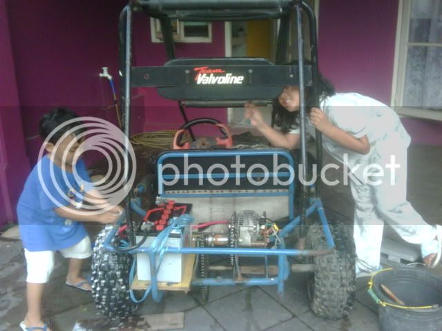
Anyway, installed the motor today, but the bench test shows that though the torque is big, it does takes quite some amps and makes my 25C 3S lippo warm up quite rapidly (this quite old battery hence might be one of the reason together with the advance timing) . Nevertheless, the ESC did not shows any excessive heats up, so I its time for the real testing.
Installed the motor
and have a quick 1 km trip including the extrime climbing in the same place as shown in the previous video. The result are:
1. Crisp throttle response
2. Smooth start up
3. No more low rpm outsync, a very noticeable difference is on the car ramp on my garage, as previously it would requires some sprint up for 2 meter to succesfully climb it up. Now I could easily literally crawl up in a very low speed from a standstill.
Video not yet available for a couple days, as I still having problem with my PC to BB connection.
Still, these are two very happy children, having their eBuggy improved (they did sat besides me during the improvement process ), washing it up for tomorrow cruises after a month project .
Anyway, installed the motor today, but the bench test shows that though the torque is big, it does takes quite some amps and makes my 25C 3S lippo warm up quite rapidly
Installed the motor
and have a quick 1 km trip including the extrime climbing in the same place as shown in the previous video. The result are:
1. Crisp throttle response
2. Smooth start up
3. No more low rpm outsync, a very noticeable difference is on the car ramp on my garage, as previously it would requires some sprint up for 2 meter to succesfully climb it up. Now I could easily literally crawl up in a very low speed from a standstill.
Video not yet available for a couple days, as I still having problem with my PC to BB connection.
Still, these are two very happy children, having their eBuggy improved (they did sat besides me during the improvement process
), washing it up for tomorrow cruises after a month project .
Similar threads
- Replies
- 15
- Views
- 5,170
- Replies
- 8
- Views
- 1,326
- Replies
- 3
- Views
- 1,582
- Replies
- 222
- Views
- 26,957