How to reverse brushless motor, even if it wont.

Joined
May 22, 2008
Messages
96
Location
Victoria, BC
Well, today I had a chance to test a theory brought on by an epiphany I had a while ago... You see, there are people in various sources on the web who say that to reverse the direction a brushless motor turns, one simply needs to swap any two power wires. Fine theory, but what about the sensor wires? Remember that model aircraft motors do not typically have sensors, whereas for some reason bicycle motors do. In any case, these sources indicate that if you swap the sensor wires in the same way, the motor will then rotate in reverse. Still a great theory. but for some reason that had never worked for me.

In any case, I wondered if maybe the reason was because the sensor wires are not colour-coded to coincide with the positions of the power wires. I was right! Today I looked a little more closely at a stator from a hub motor, and two of the three sensor wires (not including the two that deliver power to the sensors) were in opposite positions to the like-coloured power wires. In this case green sensor and power wires were in the same place, but yellow was opposite blue, and visa-versa. what all that meant is that if I switched the blue and yellow sensor wires, and the blue and yellow power wires, the motor did finally rotate backwards!

Now I'm left wondering though, why it is the motor makes more of a whine in reverse than going forwards. It still had speed and apparently had strength. Oh well, it will be fun to eventually connect a switch on my bike to two relays to make the bike go backwards. i'll have to be ginger with the throttle in reverse though!
 
carbon.nanotube.capacitor said:
Now I'm left wondering though, why it is the motor makes more of a whine in reverse than going forwards. It still had speed and apparently had strength. Oh well, it will be fun to eventually connect a switch on my bike to two relays to make the bike go backwards. i'll have to be ginger with the throttle in reverse though!

advanced timing?

There are 36 combos for phase and hall sensors + hall positive and negative leads. In my situation (bafang motor and 36-72v crystalyte analogue controller) The only combo that worked smoothly was running the motor backwards. I switched the controller into "reverse" and now it runs forward fine and smooth :D
 
Weird, since most brushless motors are neutrally timed. I think. My Golden runs the same whether it was backwards or forwards.
 
Whether or not the motor has sensors, it MAY be possible to run it off of a sensorless controller, and then switching two of the phase wires will be enough to put it into reverse.
 
Okay I think I'm going insane.
I tried setting up a reversing switch on my e-scooter with four relays, two to swap two phase wires, two to swap two hall wires. It didn't work. I checked the wiring and the relays for functionality and they were good, but in "reverse mode" the motor simply went forward shakily and weakly. I tried connecting the motor wires directly, bypassing the relays altogether, but same result. So I thought "I already did this once before, why isn't it working"?! So I connected the original test motor to the bike controller and tried again. Same thing. Then I tried it with the original controller as well: Same thing! then I wrote down all the stupid combinations of phase wires (there were six) and went through each one by one, marking the result. One locked the motor, another one made the wheel go forwards smoothly, and the rest made the motor shaky. Then I tried variants where the halls were not done the same way the phase wires were. Still no smooth reverse.
I know the test bed motor and controller worked in reverse because I remember noting the freewheel becoming a chain puller, and thinking to myself that it could be fitted to load-test other motors by electrically resisting motion while a bike motor was reversed and pulled against the test motor. Also I remember the slightly noisier operation in reverse.

So why can't I duplicate that result? And why wouldn't it work now on a different, but identical motor? It drove me nuts all last Saturday. Now it's bugging me again. It was suggested to me that 120°motors can't be reversed. Is that rue? If so why can't they? AAAAAGH!

-Colin
 
I'm employed by an electric (and non electric) bicycle, tricycle and scooter importer. We also import from Taiwan and China hub motor kits, brush type and brushless in 24, 36 and 48V. I've seen all kinds, sizes, shapes and capacity controllers but I've never, consistently found a way to reverse rotation on a brushless motor. All the motors I've toyed with are the 8 wire, hall sensor type and I've even made up a rig that allows me to quickly invert the position of the three main and three sensor wires that determine the direction of rotation. Some motor/controller combinations allow rotation in either direction with no problems but most combinations only turn smoothly in one direction. This has not been a problem when the hub motor is installed on the front wheel as it can just be flipped from side to side but in the rear there is no such luxury. I've just finished repairing a rear hub brushless motor bicycle with a bad controller and I had to try 3 very different controllers and make up all the different connnectors (they're never the same) for power, throttle, pedal sensor, brake and motor. They all worked but the first two just did not run smoothly in the forward direction no matter what combination of the 6 wires I tried. Finally I tried one that worked great but was too big to fit in the case supplied for it so I mounted it outside (better for cooling anyway) and only mounted all the connectors inside the case where the controller previously resided.
My final conclusion, and I firmly believe that I have tried more combinations of motors and controllers than anyone else I've ever encountered, is that the inexpensive motor/controllers that come from China are never consistent even from one order to another and the only thing you can count on is that it will be a problem to reverse direction should you need to.

Manny
 
It sounds like you guys really need Lyen's ebike tester, which displays via LEDs the firing sequence of phase and halls. With motors that can't be made to work with at all with a controller, assuming both are fully functional, then there may be a 60°/120° phase angle conflict between the motor and controller. This isn't an issue with the Infineon board based controllers many of us are using, because they auto sense the motor's sensor phase angle, making the phase angle a non-issue for forward or reverse.

There also exists some possibility that a motor is made to function only with a specific controller by using non-standard hall sensors. I remember a post of SteveO who had trouble getting a motor to work due to the type of hall sensors he installed during an overhaul. Fetcher brought up that BMC motors have special controller requirements (as evidenced by Kelly having a BMC specific controller) and only 1 of the 36 wiring combinations works with BMC's due to a timing advance setup.

With a standard direct drive motor that has a neutrally timed hall sensor placement, reversing direction is a matter of relative simplicity. ie Just swap 2 phase wires, and 2 hall wires. You typically won't know which 2 hall wires to switch due to the lack of consistency in the wiring of motors and controllers, where no standard exists. You do know that the forward direction hall combination isn't correct, so it leaves you with only a maximum of 5 hall combinations to try before getting the correct one.

When changing direction stick with that single 2 wire phase swap, because otherwise you will confuse the issue that can lead to a false positive. By false positive I mean a combination that spins the wheel, but isn't correct. In my experience with 7 different types of hub motors, the false positive has been in the opposite spin direct of the good hall combo. With some of these false positives the wheel spins well at no load and it only slightly different in sound. If you swapped only 2 phase wires, the false positive will be in the same direction as the original good combination, so you know it's not a good combo. The sure way to know is to measure no load current, which will be high with this false positive. These false positives are the ones that people have tried riding their bike and report no power. Be careful with them, because the high current can easily damage a motor or controller or both.

We should make a list of all motors we run across with non-standard timing. BMC is the only one I know of.

The best advice I can give anyone wiring up a new motor/controller combination is only swap 2 wires per attempt, and make sure you have good connections on each attempt. I find it easier to change halls around than phase wires by sliding the spade connectors out of the male connector. Then trying a new combo is just sliding 2 spades out and sliding them back into the female slots the other way. With my motors, finding the reverse always takes less than a minute after I swap any two of the phase wires.
 
as long as the motor is neutrally timed there will always be one combination to work in forward and another to work in reverse.

think of it this way. there are 3 phases for our example we will number them 1, 2 and 3. in the crudest form the motor will run if we energise the phases in sequence, 1 followed by 2 then 3 over and over again. so the sequence is 1,2,3,1,2,3,1,2,3 etc., etc.

but how do you know where to start? is the motor currently in position 1, 2 or 3? this is what the hall sensors are for. if the motor is in position 2, hall #2 will be activated and the controller will turn off phase #2 and turn on phase #3 to advance the rotor to the next position, hall #2 will then turn off and hall#3 will turn on. the controller will recognise this and turn off phase #3 and turn on phase #1 to continue to the next step.

to reverse the motor we need to change the physical sequence of the phases so that the sequence chages to 1,3,2,1,3,2,1,3,2,1 etc., etc. notice that this can be achieved by swaping only 2 of the phase wires and the associated hall sensors.

the problem is that there is no standard for which phase or hall is connected to which color wire. you would think that it would make sense to keep the sequence of colors between phases and associated halls the same. but this does not happen often. it is not uncommon to see combinations where the phase color sequence is Yellow, Green, Blue while the hall sequence is Green, Blue, Yellow. or any other combination. it is even not uncommon for these to change with different production runs from the same company.

so the upshot is that even if you do swap the the blue and green wires (or any other matching pair) on both the phase and the hall wires you may not have changed the sequence identically for both the phase and the halls. John is right. if it does not work on the first attempt then leave the phase wires alone. they are now in the right sequence for reverse. since we know that the original pre-swap combination will be wrong and the curent swapped configuration is also wrong, experiment with the remaining 4 combinations of hall wires to find the one that works.

when experimenting with these combinations of hall and phase wires make sure that all of your test connections are secure. early on i learned that loose or poor connections only give bad results. baring poor connections the only reason for a motor not to reverse is that it is neutrally timed.

although the motor operation i described is Half-Bridge switched and all modern controlers are Full-Bridge the concept is identical, just simpler to describe and understand.

conclusion - Neutrally timed, one combination works in forward another will work in reverse. you may just have to look for the right combination

rick
 
Nice thorough post Rick. I disagree though about the number. Of 36 combinations 3 will work in forward and 3 in reverse. For each of the 6 possible phase combinations, there is 1 good one. You just don't know for certain whether it's forward or reverse till you find it, although if you hit on a false positive first, you know the good combo spins the opposite direction. That's why on a neutrally timed motor I am guaranteed to get the right combo for the correct direction within 8 or 9 tries.
 
john,

all 3 of the working conbinations for forward are essentially identical. the only difference will be in the startting position. think of it this way. the first one would be 1,2,3,1,2,3,1,2,3. the second would be 2,3,1,2,3,1,2,3,1, and the third would be 3,1,2,3,1,2,3,1,2. although each starts with a different number each is actually the same 1,2,3 cyclical sequence.

the same woul be tre for reverse.

rick
 
rkosiorek said:
as long as the motor is neutrally timed there will always be one combination to work in forward and another to work in reverse.

With 120 degree hall timing, I have to disagree on this. The only way to properly reverse the motor direction on a 3 phase sensored controller that doesn't have a FWD / REV switch is to invert all of the hall signals, either with a tripple NOT logic gate, or mechanically by just knocking each sensor out of the stator, flipping it upside down, and sliding it back into place.

If you do as the original poster suggested and actually measure the current draw and current waveforms of a hub so arranged to spin backwards by rearranging the hall and phase sequence, you'll see that its not running smoothly or efficiently at all.

At least, that's been my experience, and I think if you try to sketch out the actual drive waveforms based on the decoding of the hall signals with the phase and hall wires rearranged you'll see that there isn't any combination that will drive the mosfets 'correctly' for all 6 steps in reverse.

Justin
 
I gone through the 36 combos on lots of motors/controller combos and written down the results, i'm with rick, there is one combo for forward and one for reverse, need to change phase and hall connections to get reverse.
Any other combo it will not run, or run rough, or not start from any position.
by coincidence i'm just trying to work out how to make an old 846 chip go into reverse,
this thread
http://endless-sphere.com/forums/viewtopic.php?f=2&t=19187
justin you wouldn't have a trace of a dx3 pad on a xie 846 controller. Or know how to put the 846 chip into reverse? teh board I have is an old xie board, with no dx3 on it. I've tried to work out from the 116 chip also how to do reverse and apply to the 846 boards since much of the circuits are still the same it appears.
Someone told me pin21 of the 116 chip was used for reverse, but I dont think thats correct it seems to be a driver pin for phase C ( along with pin 20).
 
justin_le said:
If you do as the original poster suggested and actually measure the current draw and current waveforms of a hub so arranged to spin backwards by rearranging the hall and phase sequence, you'll see that its not running smoothly or efficiently at all
This is interesting.
I got a rear hub yesterday that arrived with the freewheel threaded loosely onto the side of the motor that had the wires exiting the axle. I figured someone in the factory had just put it on the wrong side so swapped it over, bolted it up and connected a controller only to find it was spinning backwards.
I was planning to fiddle with the hall / phase combos this afternoon to sort it out but you're saying that it will never run as efficiently ? I've got a watt meter to look at the current draw but having not used this type of motor before I'd only be ballparking what to expect. :?
 
Hyena,

Is that the one with the drum brake, because drum brakes go on the right side for those scooter motors?
 
I wonder if Justin's comment is specific to Xlyte motors. I believe that their angled windings due to the splayed laminations give those motor specific direction of spin due to the hall placement on one side of the stator.

My motors have straight lams and they don't care which way they spin with one just as efficient as the other. To change direction on such motors, simply swap any 2 phase wires and 2 hall wires. You just don't know which 2 halls. It's not the same 2 colors as the phase wires you switched, so you should be able to get it in 4 tries.
 
This is really not a newbie hack, ...I would recommend for anyone wanting to try this, first, mark each wire with some type of label. Then draw their original combination. You may think it will be easy to put them back if you are having trouble stumbling into the best reverse combination, but after you've swapped them around a few times, its suprising how quickly you forget where they started out.

This thread is interesting to me because I believe there would be some usefulness to some builders, by reversing their hub-motor to flip it over and use it as a non-hub drive, pulling the left hand side of the rear wheel.

John in CR, which motors do you know of that have the straight lams? (possibly making reversal easy)
 
No John it's a normal ebike one, it does have evenly spaced threaded side covers on both sides, with a screw on disc brake adaptor used on the the other side. The picture on the website shows no wires leaving from that side of the axle so maybe they're meant to have the wires leaving on the drive side...
 
Hyena said:
No John it's a normal ebike one, it does have evenly spaced threaded side covers on both sides, with a screw on disc brake adaptor used on the the other side. The picture on the website shows no wires leaving from that side of the axle so maybe they're meant to have the wires leaving on the drive side...

The treads for a screw on brake at the same a for a freewheel. Maybe they just put the FW on the wrong side at the factory.

SpinningMags,
If Xlytes reverse at all then the wiring change is just as easy, it's just that reverse may not be as efficient as Justin mentioned, which makes sense due to the different magnet position relative the the angled coil as a magnet passes a hall sensor. One direction the magnet is just getting to the bulk of the coil, and the other it is leaving it. Maybe there are others, but I've only seen the splayed laminations on the Xlytes. The cover of mine even has a sticker with an arrow indicating the direction it should rotate.
 
John in CR said:
The treads for a screw on brake at the same a for a freewheel. Maybe they just put the FW on the wrong side at the factory.
Yeah, that's what I thought, which is why I swapped the freewheel over to the other side. Ah well, I fiddled with the halls and got it running properly (on the 1st lot of hall combos for once!) and it seems to be running fine and drawing the expected amount of current.
 
Hyena said:
Ah well, I fiddled with the halls and got it running properly (on the 1st lot of hall combos for once!)

It's really easy once you get away from that mode of changing a bunch of wires at once. For reverse, swap 2 phases, and then you will get it on the first pass of hall combo's. Now you'll never dread figuring out a wiring combo. Just watch out for those BMC motors that have some timing advance arrangement that only 1 in 36 works.
 
John in CR said:
I wonder if Justin's comment is specific to Xlyte motors. I believe that their angled windings due to the splayed laminations give those motor specific direction of spin due to the hall placement on one side of the stator.

My motors have straight lams and they don't care which way they spin with one just as efficient as the other. To change direction on such motors, simply swap any 2 phase wires and 2 hall wires. You just don't know which 2 halls. It's not the same 2 colors as the phase wires you switched, so you should be able to get it in 4 tries.

OK, it sounds like I am wrong here. It was a few years ago and I remember thinking that it should work this way, just like with a sensorless motor, but whenever I tried it I never got it to spin right, and then I convinced myself through a truth table that it couldn't be done that way.

Has someone here posted a table doing the full "36 combinations" test of the behaviour of a BLDC motor under each possible permutation of hall and phase lead? I'm speculating that laid out in this way we should have 3 cases that spin forwards smooth, 3 that spin in reverse smooth, 6 that spin forwards really rough, 6 that spin in reverse rough, and the other 18 that just vibrate?

-Justin
 
Justin,

I think you may have been right about motors not reversing as well, but it is Xlyte specific or others with the splayed stator laminations that result in the angled stator teeth. I haven't tried mine, but looking at the hall sensor placement relative to one end of an angled windings, but straight magnets on the rotor, reverse has to be different, if it works at all.

Also, at least on 2 of my motors that I'm most familiar with from changing out controllers, I only get one of those "false positives" per phase combination. ie the combo that spins the wheel but not under load. Also, on mine the false positive is always in the opposite direction of the good smooth combo. That info helps me always find the correct combo, correct direction very easily.

BTW for reverse, it's swapping 2 phases, and 2 halls, but which 2 halls for any given phase pair swap isn't certain, so a quick bit of trial and error is required.

The exception that Fechter pointed out is the BMC's which he has had to go thru all 36 combos to find the single good one.

John
 
justin_le said:
John in CR said:
I wonder if Justin's comment is specific to Xlyte motors. I believe that their angled windings due to the splayed laminations give those motor specific direction of spin due to the hall placement on one side of the stator.

My motors have straight lams and they don't care which way they spin with one just as efficient as the other. To change direction on such motors, simply swap any 2 phase wires and 2 hall wires. You just don't know which 2 halls. It's not the same 2 colors as the phase wires you switched, so you should be able to get it in 4 tries.

OK, it sounds like I am wrong here. It was a few years ago and I remember thinking that it should work this way, just like with a sensorless motor, but whenever I tried it I never got it to spin right, and then I convinced myself through a truth table that it couldn't be done that way.

Has someone here posted a table doing the full "36 combinations" test of the behaviour of a BLDC motor under each possible permutation of hall and phase lead? I'm speculating that laid out in this way we should have 3 cases that spin forwards smooth, 3 that spin in reverse smooth, 6 that spin forwards really rough, 6 that spin in reverse rough, and the other 18 that just vibrate?

-Justin
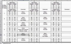
FWIW here's a partially populated table I did recently when switching to new controllers.

HallPhaseCombos.jpg
All 11 permutations I tried had some reaction. Out of those, one was good reverse, and one good forward. The ones listed as "Noisy" basically just vibrated and moved a little.

This was with a Lyen 6fet controller and a geared Cute hub.

Gary
 
John in CR said:
I only get one of those "false positives" per phase combination. ie the combo that spins the wheel but not under load
I have a GM motor new from the factory that does that. I tried every combination, TWICE (as I thought I must have missed something the first time) and got a few combos where it'd freewheel fine but when I sat on it'd stutter like it had a hall problem. In the end I concluded it must have a dodgy hall, because it works ok with a sensorless controller.
 
Gary,
A shortcut on yours would have been to swap 2 of the wires you were keeping static, as soon as you hit the valid reverse. Thanks for sharing, because it demonstrates that the false positives definitely vary by motor. I've never seen one get rotation with so many invalid combos.

Hyena,
Maybe it's a 60°-120° hall phase angle conflict between the motor and controller.

What everyone really needs is one of Lyen's ebike testers. It's a tiny box with a bunch of wires and LEDs. Plug a throttle, motor, or controller into it, and it tells you whether the item is functioning properly. It can even tell you the firing sequence directions of rotation and phase angle of the motor. I find it simple enough to find the correct wiring combo, that I'd never use it for that, but for testing for problems it will be indispensable. It's so handy in getting right down to the root of a problem, that I ordered a second one, so I have a backup for when I get more serious about building bikes.

John
 
Back
Top