Blowing 20 Amp fuses on a 500w Direct Drive Hub

bigchief

100 mW
Joined
Jun 20, 2009
Messages
45
I just finished my new E-Bike; I'm using a 36v, 10amp rated (20amp peak) 10AH LiFePo4 battery with a 20 amp fuse, a 500 watt Direct Drive hub, and a controller of indeterminate wattage.

The setup works great and takes me to 20-25mph without pedaling; the only problem is if I floor the throttle at mid-speeds, I sometimes blow the 20 amp fuse. I biked five miles to work and blew 3 fuses, each time when near or at max throttle and about 15mph. Other than that it's working great. Where would I start in trying to figure out how to prevent the setup from not drawing over 20 amps?
 
Does your controller have current limiting? Does the BMS on your LiFePO4 pack do current limiting? Preferably, the controller should be limiting the current, but BMS often includes a limiter to protect the batteries. Usually the BMS is a sharp cutoff, where the controller will just control the throttle to keep current within bounds.

From the small amount of info provided, it sounds like your battery pack is a poor match for the hub motor. Your pack is only rated to supply 360W, but your hub is rated for 500W (and they will frequently try to draw 2x rated under heavy load). You need to either find a way to implement strict current limiting in your controller or get more battery. Your batteries are at risk of dying a swift death with the current setup.

Do you have a cycle analyst, watts up, or similar meter that will let you measure the battery current draw?
 
bigchief said:
...and a controller of indeterminate wattage.
That would be the source of the problem.

The motor will take all you give it, until you have a controller to hold it back. Even if you block the throttle from full, a hill can still get you.
 
rhitee05 said:
Does your controller have current limiting? Does the BMS on your LiFePO4 pack do current limiting? Preferably, the controller should be limiting the current, but BMS often includes a limiter to protect the batteries. Usually the BMS is a sharp cutoff, where the controller will just control the throttle to keep current within bounds.

Do you have a cycle analyst, watts up, or similar meter that will let you measure the battery current draw?

I don't have a Watts Up, I might invest in one.

My batteries actually do not have a BMS, they are 12 3.3v cells in series (resting voltage of about 40v in practice). There is a BMS in the battery charger only.

I'll try to figure out the model and stats of the controller to see what it's supposed to be pulling.
 
Oh, I might have thought of something. People here talk about shunting (making a solder pool?) on a controller to draw more amps, right? Could I wick away solder from that area or use a small gauge wire or something to limit the current?
 
bigchief said:
Oh, I might have thought of something. People here talk about shunting (making a solder pool?) on a controller to draw more amps, right? Could I wick away solder from that area or use a small gauge wire or something to limit the current?

You'll need to look at what the shunt wire consists of. On a low power controller it may be only one. If there are 3, then removing one will reduce current by 1/3, and if 2 then removing 1 would reduce it by half. If there's only one, then you could file it thinner, which would be easier than finding a replacement. They're made of a special metal whose resistance changes very little as it gets hot, so you can't just replace it with any old wire.
 
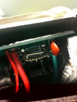
I attached a picture of the controller opened up. Is it these thingies here? There's markings for three of these jumpers, but only two are mounted. the one in front is bigger and has ridges along the top, and the second one is a smooth looking jumper and is shorter. So I should try filing down one of those, or eventually clipping one off if I still blow fuses?
 

Attachments

  • shunt.jpg
    shunt.jpg
    45.6 KB · Views: 1,399
bigchief said:
I attached a picture of the controller opened up. Is it these thingies here? There's markings for three of these jumpers, but only two are mounted. the one in front is bigger and has ridges along the top, and the second one is a smooth looking jumper and is shorter. So I should try filing down one of those, or eventually clipping one off if I still blow fuses?

You could unsolder one of the shunt legs and lift it free from the board.

When you ride, it should feel emasculated, but it probably won't blow fuses. You could then build up solder on the remaining shunt until it just blows a fuse, then shave the solder back to a "safe" amount.
 
Sounds good, I just de-soldered a leg and I'll give it a try. Thanks for the help!
 
Just go for a 25A fuse and you should be fine, those are the EB709XC series (I can tell by the shunt adjustment) and are calibrated for 21A but they will pulse above to about 23/24 for a second (literally) on initial launch at WOT (wide open throttle) but will simmer down - on my CA I could see no more than 21.7A on the User Real time display of current but when I checked the Max Amps - it was 24.7 just too fast for me to see it happen...

25A should suffice, however... you could also try 30A if that fails... but if 30A pops, you have an issue!

I wouldn't worry about the literally "INSTANT" peaks (hey maybe a slow blow 20A would suffice) and a 2C LiFePo4 will not be damaged by the transient 22 + surges...

Where did the fuses come from, I've received fuses marked as 20A before which were proven to blow at 15 or 18 in some cases...

Sadly you can't reprogram that controller - the software is not available at this time so it's not possible anymore.

Hope it helps!

-Mike
 
the reason that one shunt has the ripples in it is because they adjust the shunt value by crimping the shunt with dikes several times along the length in order to RAISE the resistance of that shunt which increases the overall resistance of the two or three in parallel. so the cuts from the dikes show that it was actually calibrated at manufacture.
 
If u think a bit deeper about it, it was indeed calibrated at the factory but physically calibrated with minor tolerances which obviously aren't (never are) accounted for with software recalibration.

One fix would be to try wicking up some of the solder near the base of those shunts but I don't think it's an issue, they will peak a tad higher than rated but no longer than a second by default (block time)

-Mike
 
OK, so get a load of this: I completely desoldered the leg of the crimped shunt, leaving only the middle shunt in. I was expecting the bike to have it's speed and acceleration gimped. Turns out the bike is now performing *exactly* the same as when I had both shunts in, only without any blown fuses (and I've been flooring it for about an hour). I shudder to think of how many amps that must have been trying to draw if I could remove an entire shunt and still keep the same performance. I'm hitting a top speed of around 20mph, and it took me up a 15-degree incline without peddling, at a faster speed than my super-high torque Heinzmann could manage. This thing is amazing!

Thank you all for the help, especially TylerDurden who was right on the money.
 
Back
Top