Thud
1 MW
New edit:
Seems there are few of these motors getting pulled off the shelf & guys are starting to use their old stock finally, I am getting some questions regarding them. Here is the recommended set up if your serious about getting the most out of them & a cheap controller:
Use Xpd in the tech section to flash settings
Do not solder the shunt (& throw all the calibration out the window)
Do the math with your voltage to arrive @ 6kw @ use that for battery amps.
Set the phase current conservatively (start with battery amps) & make small increases untill your happy with your accelleration, or the controller starts to show some heat.
Most importantly set the block time to zero.
This method has been tested on the race track & in the neighborhoods....you can drain a 25ah pack without overheating in controllers or motors from my experience.
Now go read the whole thread & see all the mistakes
Edit:
Rather than starting a new thread I thought I would add this info here. We will tear down & re-wind a brand new Turnigy 80/100-130 from scratch.
Step 1-Disasembly:
#1 inspect the shaft for any nicks or bump that would impead the removal through the bearings.
#2 remove the 4 inside bolt circle 5mm cap head bolts & remove the end cap (its a light press fit & pops off easily)
once removed your motor looks like this: (notice the yellow Phase wire was actually shorting to the end plate..this is a brand new never run motor!)
(Sorry guys, photo bucket pruned a few pics from my libraries...I'll have to take new ones....but these motors have dried up or gone the way of the dinosaurs)
#3 remove the circlip & spacer...& the 4 screws holding the skirt bearing to the can. use a proper fitting screwdriver as the screws are kinda soft.
#4 Using a plastic faced hammer, gently tap the end of the shaft a few times, this will loosen the skirt bearing from the can, once free we are ready to press the can off the motor.

#4 press the magnet can out of the bearing tube. You see I am using the stock motor mount to gain some purchase, I use a singe bolt from the end cap. My technique is to hold the motor mount with my index fingers & press the shaft out with my thumbs.If the shaft is properly smooth, it will slide right out.
BE CAREFUL the magnets are very strong & if you change your grip you can potentialy receive a nasty pinch.


You see I had a slight burr on the end of the shaft & its hanging in the bearing race. I just installed a 4mm cap head screw & tapped it through gently.
Now you can tap the skirt bearing off the bearing tube. Use gentle taps & apply preasure 180 degrees to the bearing & it will pop right off. Next remove the bearings from the tube, I use a length of 10mm rod with a very square face on it, reach through one end to catch the inside race of a bearing. Now alternate tap's in 180 degree incremants & the bearing should slide out also.
congrats. You have diassasembled your motor & it looks like this.

In close up, you can see several "flyers" or loose wires scattered about the stator. Lots of human error found throughout the assembly...several single strand shorts were obvious..but these are wound with 90ish strands of 33-ga wire so I don't really know if this motor would survive very long in its intended applicaion. My big concern is the shorted phase wire...so I dremel'd all the razor edges back & smoothed any areas that may come in contact with the wires.

FRESH WINDINGS
Lets get rid of this original set up & build us a motor, one that you can't buy.
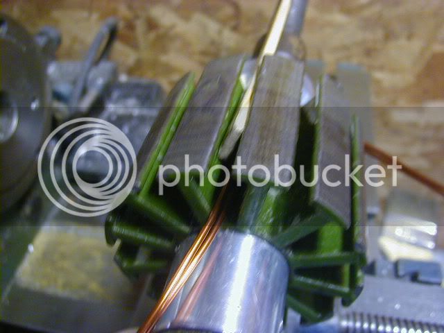
1st, I use a cut off wheel on the mighty dremel & make a slot through the super glue that the cheaters used to hold the windings onto the stator. We are very careful not to cut down to the stator & damge the precious green epoxy insulation on the stator.

Once through the boundry layer of glue, I use a utility knife to cut the remaning windings. Careful fiddling with a Jewlers screwdriver & needle-nose pliers will clean out the stator.
[youtube]w0cillAWq6k[/youtube]
RE-WINDING
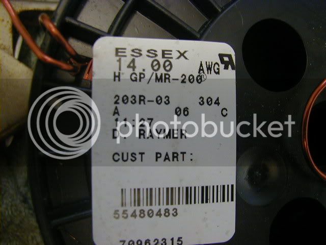
This motor originally was an 8-turn/delta & will become a 6-turn/wye with 2 X 14-ga wire.
Just to overveiw the changes:
(all #s taken from "Drive Calculator")
parameters------------Stock-------rewind
copper cross section--18.9--------25.0
R (mOhms)-------------30.1--------13.5
Delta R ----------------20.1--------9.0
WYE R------------------60.2--------27.0
COPPER GRAMS-------254.5------357.7
Addendum: just confirmed the re-wound Kv is 133
I spun the motor in a lathe at 800-RPMs & it genrates 6.01V on each phase
rpm/volts = Kv
You can see the re-wind video
http://www.youtube.com/watch?v=7i_GIXxUlQM
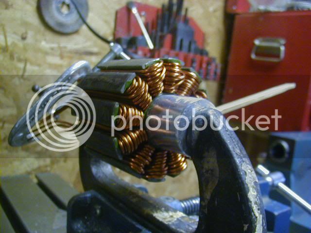
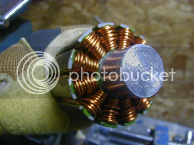
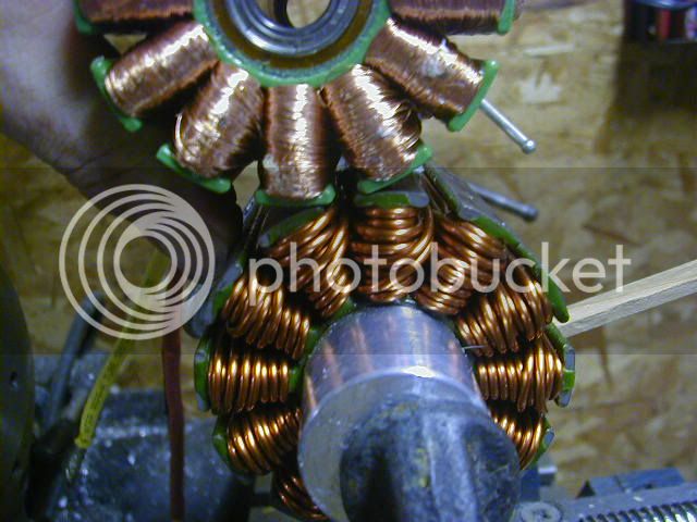
(remember...low expectations) Here it is all wound up & ready to rock.

& next to another stocker:

Additional Notes:
I did not take the stator off the bearing tube for this project.
I really must build a decent Dyn-O-mometer...need to re-read Jeremys links on load sensors.
hope this answers a few questions I been getting via PM's
Added 4/28/2011: Winding information to answer questions about Kv & wire lengths
1st is a chart of turns & expected Kv result. This is completely credited to Mr Jeremy Harris, & has proven to be a valuable quick reference for me.
Again, Thanks to Jeremy Harris.
I have found this chart to be super accurate with the 80/100 turnigy's & all RPM's are assumed terminated in Delta...
for a lower RPM "Wye" termination, divide by 1.73 to get your new Kv example- 132/1.73= 76-Kv
See how flexible these are for getting anything you want?
Next are some Jpeg's of drive calculator with some winding scenario's
I compare the copper cross section's & resistance values of the different winding senarios...to get an idea of what I will end up with.
View attachment 80-100 turnigy winds.zip
next some info for the 80/85 motor:
View attachment 80-85 Turnigy winds.zip
and this ought to get a few guys into trouble
Added 5/21/2011:
I have been testing & blowing-up bicycle controllers for almost a year...I have a small 63mm motor running with external halls that always just worked...& have been fooling around with external hall sensors on the 80mm motors...today I went with internal Halls and can finally say that the XieChang controllers will operate the motors satisfactorily.
1st time out: NO throttle cut outs, my wheelie power in low gear is restored! still a little soft on the high gear acceleration, but I am only programmed for 88 phase amps ATM...controller ran cool, motor runs cool after a mile of WOT. Time to ship this one out & make someone famous.
Seems there are few of these motors getting pulled off the shelf & guys are starting to use their old stock finally, I am getting some questions regarding them. Here is the recommended set up if your serious about getting the most out of them & a cheap controller:
Controller settings:So far, I haven't built a better motor & controller set up than the 6-turn, 2-in hand, 14G, dlrk/wye terminated motor...run the thing with a 12 or 18-FET xie-chang with a 6-Kw limit on 20 LiPo cells & you will not find a better RC power combination [with external hall sensors].
Use Xpd in the tech section to flash settings
Do not solder the shunt (& throw all the calibration out the window)
Do the math with your voltage to arrive @ 6kw @ use that for battery amps.
Set the phase current conservatively (start with battery amps) & make small increases untill your happy with your accelleration, or the controller starts to show some heat.
Most importantly set the block time to zero.
This method has been tested on the race track & in the neighborhoods....you can drain a 25ah pack without overheating in controllers or motors from my experience.
Now go read the whole thread & see all the mistakes
Edit:
Rather than starting a new thread I thought I would add this info here. We will tear down & re-wind a brand new Turnigy 80/100-130 from scratch.
Step 1-Disasembly:
#1 inspect the shaft for any nicks or bump that would impead the removal through the bearings.
#2 remove the 4 inside bolt circle 5mm cap head bolts & remove the end cap (its a light press fit & pops off easily)
once removed your motor looks like this: (notice the yellow Phase wire was actually shorting to the end plate..this is a brand new never run motor!)
(Sorry guys, photo bucket pruned a few pics from my libraries...I'll have to take new ones....but these motors have dried up or gone the way of the dinosaurs)
#3 remove the circlip & spacer...& the 4 screws holding the skirt bearing to the can. use a proper fitting screwdriver as the screws are kinda soft.
#4 Using a plastic faced hammer, gently tap the end of the shaft a few times, this will loosen the skirt bearing from the can, once free we are ready to press the can off the motor.
#4 press the magnet can out of the bearing tube. You see I am using the stock motor mount to gain some purchase, I use a singe bolt from the end cap. My technique is to hold the motor mount with my index fingers & press the shaft out with my thumbs.If the shaft is properly smooth, it will slide right out.
BE CAREFUL the magnets are very strong & if you change your grip you can potentialy receive a nasty pinch.
You see I had a slight burr on the end of the shaft & its hanging in the bearing race. I just installed a 4mm cap head screw & tapped it through gently.
Now you can tap the skirt bearing off the bearing tube. Use gentle taps & apply preasure 180 degrees to the bearing & it will pop right off. Next remove the bearings from the tube, I use a length of 10mm rod with a very square face on it, reach through one end to catch the inside race of a bearing. Now alternate tap's in 180 degree incremants & the bearing should slide out also.
congrats. You have diassasembled your motor & it looks like this.
In close up, you can see several "flyers" or loose wires scattered about the stator. Lots of human error found throughout the assembly...several single strand shorts were obvious..but these are wound with 90ish strands of 33-ga wire so I don't really know if this motor would survive very long in its intended applicaion. My big concern is the shorted phase wire...so I dremel'd all the razor edges back & smoothed any areas that may come in contact with the wires.
FRESH WINDINGS
Lets get rid of this original set up & build us a motor, one that you can't buy.
1st, I use a cut off wheel on the mighty dremel & make a slot through the super glue that the cheaters used to hold the windings onto the stator. We are very careful not to cut down to the stator & damge the precious green epoxy insulation on the stator.
Once through the boundry layer of glue, I use a utility knife to cut the remaning windings. Careful fiddling with a Jewlers screwdriver & needle-nose pliers will clean out the stator.
[youtube]w0cillAWq6k[/youtube]
RE-WINDING
This motor originally was an 8-turn/delta & will become a 6-turn/wye with 2 X 14-ga wire.
Just to overveiw the changes:
(all #s taken from "Drive Calculator")
parameters------------Stock-------rewind
copper cross section--18.9--------25.0
R (mOhms)-------------30.1--------13.5
Delta R ----------------20.1--------9.0
WYE R------------------60.2--------27.0
COPPER GRAMS-------254.5------357.7
Addendum: just confirmed the re-wound Kv is 133
I spun the motor in a lathe at 800-RPMs & it genrates 6.01V on each phase
rpm/volts = Kv
You can see the re-wind video
http://www.youtube.com/watch?v=7i_GIXxUlQM
(remember...low expectations) Here it is all wound up & ready to rock.
& next to another stocker:
Additional Notes:
I did not take the stator off the bearing tube for this project.
I really must build a decent Dyn-O-mometer...need to re-read Jeremys links on load sensors.
hope this answers a few questions I been getting via PM's
Added 4/28/2011: Winding information to answer questions about Kv & wire lengths
1st is a chart of turns & expected Kv result. This is completely credited to Mr Jeremy Harris, & has proven to be a valuable quick reference for me.
I've been trying to reverse engineer the constant to estimate the Kv for this size motor, based on the sparse data we have at the moment. This is what I've come up with in terms of turns and Kv:
Turns - Kv
1 - 1060
2 - 530
3 - 353
4 - 265
5 - 212
6 - 177
7 - 151
8 - 132
9 - 118
10 - 106
11 - 96
12 - 88
13 - 82
14 - 76
These figures are pretty much the best fit I can get to the known data points, and they would apply equally to someone rewinding an 80-100 motor
Again, Thanks to Jeremy Harris.
I have found this chart to be super accurate with the 80/100 turnigy's & all RPM's are assumed terminated in Delta...
for a lower RPM "Wye" termination, divide by 1.73 to get your new Kv example- 132/1.73= 76-Kv
See how flexible these are for getting anything you want?
Next are some Jpeg's of drive calculator with some winding scenario's
I compare the copper cross section's & resistance values of the different winding senarios...to get an idea of what I will end up with.
View attachment 80-100 turnigy winds.zip
next some info for the 80/85 motor:
View attachment 80-85 Turnigy winds.zip
and this ought to get a few guys into trouble
Added 5/21/2011:
I have been testing & blowing-up bicycle controllers for almost a year...I have a small 63mm motor running with external halls that always just worked...& have been fooling around with external hall sensors on the 80mm motors...today I went with internal Halls and can finally say that the XieChang controllers will operate the motors satisfactorily.
1st time out: NO throttle cut outs, my wheelie power in low gear is restored! still a little soft on the high gear acceleration, but I am only programmed for 88 phase amps ATM...controller ran cool, motor runs cool after a mile of WOT. Time to ship this one out & make someone famous.