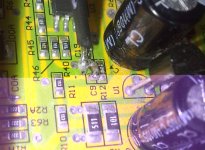
Infineon has REGEN BRAKING (and more)

Ahh so you have had it over a year - interesting.

Bad news I'm afraid, those 7XX series controllers don't have software at all available so no easy way to mod squat.

That said - the fets are likely P75&75NF stock stuff for infineon - just added more for additional current handling and on that topic - the standard stock stuff comes programmed as rated so 30A for primary current and 2.5X for the phase current so 75A (theoretical limit on the stock fets) - I imagine they implemented both syncronous rectification (3 low side, 2 high side per phase) and I would wager even vector based control is in there (timing advance for more top end) but you can't program it - and default is 100%

-Mike
 
I've seen that fet reference before, but a search for P75&75NF comes up empty. I want to compare it to real 4110's especially from a thermal standpoint. For over 12 months of the 19 months I was running one controller, I ran with a modified shunt using a short shunt wire on the bottom that raised the current to 50-60amps, along with the higher voltage.

I pulled a real bonehead move recently and modified that controller's shunt further instead of starting with another of the 5 I originally had. Not only did that cost me a proven modified controller with acceptable performance by overdoing the shunt, but I killed another one trying to copy the shunt mod from a year ago. The ability to program would be great, but I have 4110's so if they are a thermal upgrade, then I'll swap the FETs as part of a repair job. Doing that along with going to a switcher for the voltage stepdown, should allow higher performance while staying durable, while keeping the controller case stock instead of getting radical with force air cooling like I've done one of my remaining 2 controllers.

At my current 74V nominal pack voltage, my motors stay in current limiting up to 37mph, and that is proving deadly for controllers when I try to get the acceleration I want. I want to be able to carry 50lbs of cargo, which puts my total load at 400lbs, up nearby hills of 8% without worry. If I can't do it through controller mods, then my next option is going to all the trouble of a series/parallel switching system just so I can cut Kv in half for hills to relieve system stress.

John
 
John, you just need a 36 fet controller with phase and battery limits set 1:1 at the max safe value that controller can handle. Would solve all your problems!
 
tostino said:
John, you just need a 36 fet controller with phase and battery limits set 1:1 at the max safe value that controller can handle. Would solve all your problems!

I don't think that necessarily solves the problem, because I don't believe it's the current itself, but switching it on and off at partial duty. Every single controller failure I've had, with only one exception, occurred at partial throttle and less than max current and lower phase currents than previously run through the same controller.
 
Switching losses can be pretty big I know, but the more fets your distributing that heat to, the less of an impact it has.

I made up the attached spreadsheet to try and figure out what controller losses would be in every instance. I'd take a look at it if I were you just to see.

Edit: correcting complete lapse in brain function.
 

Attachments

  • Controller heating.zip
    6.5 KB · Views: 130
tostino said:
Switching losses can be pretty big I know, but the more fets your distributing that fet to, the less of an impact it has on heating.

I made up the attached spreadsheet to try and figure out what controller losses would be in every instance. I'd take a look at it if I were you just to see.

Thanks,
Nice spreadsheet. Those losses go up pretty incredibly with less than 100% duty. Decreasing the current has a much greater than linear reduction in losses too.
 
I'm helping dbaker program his infineon 116, EB212, 72V60A controller for regen.

he's running 24s lipo. any suggestions how to mod r12 appropriately? i guess LVC for him is 79.2V...

we added a 1k resistor bringing the measured resistance down to 500ohm i think. then I started having doubts... :oops:

suggested phase current setting?
 
After reading Knuckles post about his mods to create regen for his 72 volt NiMH packs I understand the stock R12 value is 1200 ohms. So when we paralleled 1k we brought R12 down to 546 ohms. This brings the regen voltage up to 60v x 1200/546 = 132 volts. We need to raise R12 to bring the regen voltage back to 100 volts. Working the equation backwards: 100v = 60v x 1200/R12 or R12 = 60v x 1200/100v = 720 ohms. 1/720 = 1/1200 + 1/x solving for x gives x = 1798 ohms
 
XieChang Controller Regen (All Models):

1) Regen DOES NOT bring wheel to complete stop.
2) Regen has an upper (programmable) voltage limit (HVC or high voltage cut-off).
3) You can't "regen" more current than your battery chemistry/size can accept at the HVC.
4) Front wheel Direct Drive motor is best for regen braking IMHO.
5) Using right ebrake lever for "ebrake" and left ebrake lever for "BK-GND"
allows throttle based variable regen (program controller for throttle regen).

no brake levers ... allows coasting during low throttle.
right lever only ... cuts controller but no regen.
left ebrake only ... throttle controlled regen.
both ebrakes ... full regen down to near full stop.

pasta said:
Good information - that helps. A few stupid noob questions below... I hope you don't mind!
What is your experience with the controller by keywin?
Can you tell me something about the compatibility of XieChang controllers and my setup? I have mostly crystalyte products from Justin (ebikes.ca). What are the changes I need to do? (connectors/wiring similar?)

Knuckles said:
XieChang Controller Regen (All Models):
1) Regen DOES NOT bring wheel to complete stop.
2) Regen has an upper (programmable) voltage limit (HVC or high voltage cut-off).
3) You can't "regen" more current than your battery chemistry/size can accept at the HVC.
What determines that current? Can I regulate it somehow or are there motor / battery combinations which just don't work? (current too high)
Justin's study is quite interesting ( http://endless-sphere.com/forums/viewtopic.php?f=2&t=7891) but he doesn't actually say what his setup is, so I don't know how general those results (i.e. the generated return current) are... :(

Knuckles said:
4) Front wheel Direct Drive motor is best for regen braking IMHO.
5) Using right ebrake lever for "ebrake" and left ebrake lever for "BK-GND"
allows throttle based variable regen (program controller for throttle regen).

no brake levers ... allows coasting during low throttle.
right lever only ... cuts controller but no regen.
What's the purpose of cutting the controller? (I only know of this as some kind of safety feature...)

Knuckles said:
left ebrake only ... throttle controlled regen.
So, any "reverse current" goes back to regen.
Also, I am trying to get an idea of the braking force, i.e. for instance the amount of reverse current that's generated. That would also help me understand if my batteries can actually handle it; that must depend on the windings, rpms, motor type... any idea where I can find that information? Any experience with a 5303 motor?

Knuckles said:
both ebrakes ... full regen down to near full stop.
You are saying "near full stop"; what determines the lowest speed?

Comments are welcome ...
 
Hi
Two things for you to check, first what do you use to control the speed settings do you have a LHM switch or similar or a speed limiter switch if you do make sure that the speed setting were set as they should be also that you are on switch mode, if you have a single speed system then also check that you are on switch mode and the speed 2 setting is set to at least 100% you can set it as high as 120% if you want. The second thing to check is a bit more difficult checking the voltage range of the output from the throttle, from tests I did about 2 years ago I found out a lot about what the infineon would do, for one set of tests I had to have a steady throttle voltage input so I setup a system to me sure the voltage coming from a throttle setup from this I was able to get a lot of information I also found that the voltage range for a throttle is from 0.8V to 3.3V and if things went a long way over that some very strange things happened.
I think you will find your problem will be in the speed settings good luck.

Geoff
 
John in CR said:
I've seen that fet reference before, but a search for P75&75NF comes up empty.
Do you mean the STMicro P75NF75 (or the B75NF75)?
http://www.alldatasheet.net/view.jsp?Searchword=STP75NF75
http://www.alldatasheet.net/view.jsp?Searchword=STB75NF75
 
solarbbq2003 said:
just to confirm 6 fet board uses 1k2 resistor ( 122 ) lvc set for 42v approx

Today I opened my 6FET 17A 9c controller to find the R12 and mod it to get 62.5V instead of 60V regen voltage. I was surprised to see that the R12 had 242 written on it (instead of 122), which indicated the board used double the resistance of standard boards. I am now confused what to do. I intended to parallel the R12 with a 100k pot set to 24kohm, but does this mean I should set it to 48kohm instead? Don't want to blow the 63V caps, although my battery only has 15 lipo cells so I shouldn't get past 63V anyway. Anyone seen this board before?
 

Attachments

  • 6FET_R12_s.jpg
    6FET_R12_s.jpg
    197.9 KB · Views: 1,145
If your batteries are full, it might be possible to go past their normal max charge voltage if you did a lot of regen right as you start riding (like a long downhill right after you start out from a charge), so it could be possible for regen to damage a controller this way.

I think that's what happens to BionX controllers at 40+MPH based on some recent posts in a thread about that.

I dont' knwo what resistor values you need, though, to do what you want. :(
 
I'm not regen braking with a hot off charger battery, of course. But being limited to 60V means I can only regen brake after my battery is 30-35% discharged. My controller has 31.5V LVC handwritten on it, and a 2.4k R12 resistor (parallel to the C9 cap). How do I test the max regen voltage? Just riding at different voltages and looking at my wattmeter to see if I get any reverse current?
 
So I paralleled the 2,4k pot with 50k. Connected BK and GND. Now the controller won't do anything. If I disconnect the BK-GND, it works OK again. Can't really find any resource about regen on a 6FET 9c board. I may just give up on this, but still I'd like to know why activating e-brake disables the whole controller instead of just locking up the wheel.
 
The controller might be programmed to disable throttle instead of regen breaking. It prob needs to be reprogrammed.
 
I don't know about anyone else, but I had a really difficult time with the R12 mod. There was only one through hole on the ground side, so I had to solder the other side(leading to the mcu through a cap)to the smd resistor. It works, but I am not too confident that it will hold very long.

Has anyone else run into this problem and have a beeter solution? It seems Knuckle's board version had a through hole on each side of R12.
 
The trouble with an idle mind and hands is that they start thinking of new things tinker with. I am waiting ( again ) for the return of my battery box ...for my still un completed bike.

I started thinking about the control on the bars, and how to fit them, do i need new gear change levers, etc...that got me wondering about my re-gen braking.

Now I do not want it for re charging the batteries as i have read enough to know that this is not really worth while..I only really wnat the braking effect.

Here is what I have
18 FET Lyen edition Overclocker ready modded controller
rear 5304
20 s lipo

So from what I understand I will need to modify R12..Have sent Lyen an e-mail to confirm this.

But where in the software is the e-brake voltage set..is this the "Highest Voltage Box? I have 55, 60 and 70 Volt options only.

I have about 18 threads up on the screen here in front of me, and am getting a bit bogged down in what I actually need to do...Probably nothing...at least till I get the bike running...at least I can avoid f****ng the controller up before I even ride the bike. But when i do do the mod, where do i start...what other info am I going to have to get before I can make any decisions

Cheers

Neil
 
Neil- Check out the last page of this tech doc. You've probably read it. It talks about ways to mod the LVC and regen voltage with out to much mods to the controller. I would like to do this also, so if you figure it out, be sure to post pictures!
 
Hi, and thanks for that link.
No , I had not seen that google doc.

I had seen a couple of references to a single reference point being created, and it being an idea to do 'in the pipeline' ...but never came across any reference to it being done. May well have been buried somewhere within one of those 10 page plus threads that soon begin to make you loose the will to live :)

To avoid any damage to the controller, before I even get the bike running...I am going to leave the mod for the moment, at least till I have got he bike together and can be sure that my still new and un connected controller does work and is not a dud out of the box...If it does not work, when firs connected, at least I'll have eliminated one cause of failure (ham fisted soldering or zapping static sensitive devices !)
 
Hi well having had to have my controller apart ( blown FETS) I can look more closely at the board...Unfortunately different board to the one in the Google doc.

Have found R12 and think I can find the places to fit a parallel resistor

got to get a soldering out anyway to replace the FETs so may do the regen mod too
 
ufa.hujuk said:
:D Thanks for Your quick replay.
I took a few Pic's of my controller .
At the Rear side there is some contacts described.
I figured some of them out:
SM -- some component's missing ---possibly speed output from MCU
AUX-- one resistor 1,5 k to JZ102 left contact ( ? RX-data?)
VCC-- Batterie 36 V +
JZ102--- ? Programming input? if I compare these thread on EB812 boards
SA--
SB-- 3 lines to the hall sensors of the NC-motor JZ-RH205
SC--
Gnd-1 ...Gnd-10--- Signal ground for different in/outputs
BK-- ?regen break? when switched to Gnd - I put thes line to my right hand break handle "until now no action"
SL-- speed limit when grounded Gnd-4 -- "worked in the original configuration"
EBS-1-- Switched off Pedelec action -- " original attached to the hand break levers " ( left and right)
TA-- signal from PAS ( pedelec sensor ) " startet full support after 3/4 rotation of pedals" I d'ont like this way !!!
SP-- throttel signal ( 1,3 - 4,2 V ) " worked in the original config without pedaling" not to the German trafic rules !
Here the pads , which I d'ont know:
X1 , X2 , X3 , HF , TB , P1 , P2 , P3 , EBS+ , XC , LED , SR
Is there any where a explanation on those contacts ???
The contacts of JZ102 from top and from right I conected to:
RX-data to Rs232 9pol pin 2
TX-data to Rs232 9pol pin 3
middel no conection ? what is this ?
+5v to RS232 9pol pin 9 ( normal RI wired to 5v+ from usb pin 1
Gnd to Rs232 9pol pin 5
Transmit started "no reaction of the program designer , only greyed and blinking Transmit Gauge"
So far my experience with this controller , labled Nine continents 36V, 17A max current
Who can help ?
Best regards and nice biking
Udo

on my cheap chinese not branded 250 and 350 watt controllers, wich have a motor cutoff wire to connect to the brakes; but couldnt actively regen, if i connect pads to ground by bridging them to the brake pads( wich connect to ground when brake is applied ) then the brake levers instantly are able to do regen braking, a function they didnt have brought out but appears to be available ( and working ! ) ,on the pcb - it is briding the ' xh ' Pad to the brake low pad on pcb to enable the regen. i found this out by reading on http://rdkzq.com/English/html/621473521.html - but thanks for mapping out the pins ! it got me to here - thomasdb.net
 
geoff57 said:
solarbbq2003 said:
TB is the new one and what that is doing we do not know yet

TB gets on our bikes 5V, when the controller is powered on. Pull it down to ground (no resistor, just shortcut) and the bikes immobility function gets activated. This means: the motor is doing everything to prevent the wheel being turned
 
Back
Top