Doing the Math

When discussing airgap, flux density, etc. it's helpful to understand that magnetic flux forms closed circuits just as electric current does, and we can analyze it using the same principles. Magnets behave like voltage sources, the permeability of materials is analogous to conductance (inverse of resistance), and magnetic flux becomes analogous to current.

Let's consider the electric analogy. Take a simple circuit with a source and two resistors in series, one 1k-ohm and one 1-ohm, for a total resistance of 1.001k. It should be obvious that the 1k resistor determines how much current will flow while the 1-ohm resistor has relatively little effect. In a magnetic circuit, iron or another magnetic material has a much, much higher permeability than air. So, even for a very small airgap, the permeability of the air dominates and determines how much flux will flow. Copper is not a magnetic material, so as far as the flux is concerned it's no different than air. Flux requires a closed circuit, so the total airgap around the circuit is what matters.

In your design, the wider airgaps around the outside will increase the magnetic "resistance" there. Just as it would in an electric circuit, that will cause the flux to concentrate toward the inside. The total amount of flux will probably be lower as well. Placing wedges of magnetic material in the gaps between magnets will help with this.
 
rhitee05 said:
When discussing airgap, <snip>...
... Placing wedges of magnetic material in the gaps between magnets will help with this.

The idea you tender has merit. My only concern is one of cogging. However since the iron (or similar material) is in the path of the magnets and not in the stator, should we presume the affect is nil? Maybe we should add adhesives & fillers to the Magnetic Wire & Nd Magnets Reference
:)

Best, KF
 
Adding filler material to the rotors would not cause cogging, and I do not believe it would add eddy losses either.

Cogging is caused by magnetic interaction between the rotor and stator. If the stator is made of entirely non-magnetic materials, as in a coreless motor, no cogging can occur regardless of the construction of the rotor(s).
 
Right then, I’m on the hunt for bonding agents and magnetic fillers this week. If you good lads should find one of interest I’d be much obliged if you tossed the hot potato my ways please. :D

Hmm, silly question: With regards to my post on Fri Sep 10, 2010 4:59 pm, I calculated Inductance (L) to be 26.43 μH. Is that math correct? Admittedly it hasn’t caused me to lose sleep, nonetheless I am a bit concerned about accuracy. Pesky thing that – accuracy. :roll:

Cheers, KF
 
Kingfish said:
Admittedly it hasn’t caused me to lose sleep, nonetheless I am a bit concerned about accuracy. Pesky thing that – accuracy.

I don't want to crush all of your hopes and dreams, but in this case accuracy is the realm of FEM tools or a ridiculous amount of time with equations and integrals. :) We really only have equations for the most trivial of geometries, and even those are likely to be upset by the collision with reality to some degree. But, since you asked...

<deep breath>

Starting back with the calculation that you need 2.53m of wire for X torque, assuming Y current and Z flux. That's all well and good, but that's only valid for 2.53m of wire in the radial direction. The equation F = IL x B is a vector equation, and the directions of L and B determine the direction of F. In order to produce a force that is entirely in the tangential direction, L must be in the radial direction (assuming B is perpendicular to the surface). If L is offset from the radial direction, then only a portion of the resulting force will the in the useful tangential direction and the rest will be in the useless radial direction.

The circular geometry of your example spiral winding is actually easy to analyze. It so happens that the "effective" length of each half-circle of wire is 2*r, so the effective length of the coil is the actual length multiplied by 2/pi. To get the desired effective length of 2.53m would actually require a coil of about 4m of wire. Only about 64% of the wire contributes to torque, but it all experiences loss. The exact percentage varies depending on geometry but it's impossible to get 100%.

Regarding the inductance, the spiral happens to be one of the simple geometries that we do have equations for. However that will not be the same as the wedge-shaped coils shown in your picture. Even if you did find a way to calculate the open-air inductance of that coil shape, it would still be different in situ because of the presence of the permanent magnets and magnetic materials. It really is almost impossible to make an accurate calculation, there are just too many factors which will affect the inductance of the physical coil.
 
Ahh well, my Cabernets are crushed, but not my spirit! So – moving right along, this means that we will have to be rigorous with our deductive testing :)

I might as well design from the outset with planned losses. Let me step back a moment then to gather new examples to study, for if the concept can be understood I will be better for it than hunting for boar guilelessly armed with a blunt stick :D

There are several questions now and I shall try to keep this organized; the proverbial can o’ worms has been kicked:

Air Gaps and Filler:
Briefly I investigated what I think might be a more suitable approach than an initial idea of some additive to the bonding agent.
  • Soft Core material: Ignored.
  • Electric Steel Laminations: 4000X that of air. Good choice and commonly available even locally in my metro.
  • Permalloy: Twice that of Electric Steel. No sources.
  • Mu-metal: 5X that of Electric Steel. Expensive, though has my imagination twitching wildly.
This now brings up a question of construction, and methinks the most economical would be to have wedges that fit between the bar magnets rather than a challenging water-jet-cut cage. I’m just thinking out loud; the wedges would be very cheap to fabricate, less waste of material, and better than a poke in the eye – as in doing nothing. See Figure 1.

Fig-1.png

(Green) Electric Steel Lams between magnets

Magnetic Circuit:
Similarly, I got to thinking about completing the magnetic circuit as you well pointed out. On the left side of Figure 2 is a representation of the initial assembly: Two rotors with magnets separated by a cap at the top and bearings at the bottom (not shown), with a stator in the center and copper in-between.

The second idea to explore is using a horseshoe shape for routing the flux as displayed on the right of Figure 2. Fanciful, though I wonder how practical. Moving on…

Fig-2.png

Double-Sided Rotor & Stator arrangements

Simplistically we’re taught that the magnetic force of attraction is inversely proportional to the square of the distance. However in a double-sided Halbach arrangement, the calculations are expressed here:

I bought the book, but found the references on Google first. Actually the section begins on Page 107, with the Equation for Peak Flux at the top of Page 109 (3.42), and in the double-sided configuration with 3.45 & 3.46.

Bm0 = Br[1 - exp(-βhM)]((sin(π/nM))/(π/nM)) [3.42]
Solve for Bm0, where
  • hM = 6.35mm (1/4-inch)
    nM = 4
    β = 2π/la,
    la = nM * (hM+ Ag) where Ag = median airgap between magnets = 10mm. This figure will vary depending on the ID of the rotor face and the number of poles in the array.
    If I use an N52 cube magnet, Br = 1.48
    Therefore, Bm0 = 0.61 T
We can use 0.61 T if you like, but I rounded down to 0.5 T for the sake of discussion. :)

The part where I’m a little bit lost is βx and βz, however I have space between the discs (z) as 10 mm (again for the sake of discussion).

I’m going to hold on the Winding Calculation until we sort out the Flux Density.

Have I lost anyone? :roll:
~KF
 
Don't take anything I said to mean that there isn't value in analyzing a simple case like the one you used. Just have realistic expectations. Also, even a not-quite-right expression will (usually) give a result that's in the same ballpark as reality. That can be instructive, too!

Kingfish said:
This now brings up a question of construction, and methinks the most economical would be to have wedges that fit between the bar magnets rather than a challenging water-jet-cut cage. I’m just thinking out loud; the wedges would be very cheap to fabricate, less waste of material, and better than a poke in the eye – as in doing nothing. See Figure 1.

Wedges sound reasonable. You're along way from construction, but a word of magnet caution - those wedges will be powerfully attracted as you try to put them in place! I wouldn't worry too much about using a high-end magnetic material, I doubt you would be able to tell the difference. The airgap will still dominate the magnetic circuit. At this point I feel it does beg the question - at what point does the effort of making the Halbach array make it worthwhile to do the simpler wedge magnets and flux ring instead?

Kingfish said:
The second idea to explore is using a horseshoe shape for routing the flux as displayed on the right of Figure 2.

You're getting the idea, which is good, but this is not necessary and would actually be counterproductive! The complete magnetic circuit in this case does not run through the air around the stator, but instead through adjacent pairs of poles on the two rotors. That's the function of either the flux ring or Halbach array. A little flux bridge like you've drawn, if it had any effect, would likely serve to divert some of the useful flux around the stator. You're thinking in the right direction, though.

Your book looks like a good reference. In this case Bx and Bz refer to the two components of the flux vector. Bz is the useful flux perpendicular to the magnet faces. Bx is wasted flux parallel to the faces. The equations express them as functions of x, moving horizontally across the array, and z moving from one rotor to the other. Probably the most useful value for you would be the value of Bz centered between a pair of poles. In that case, z=t/2, so the two cosh terms will cancel and the sine will be 1 at x=0, so Bz=Bm0.
 
Probably the most useful value for you would be the value of Bz centered between a pair of poles. In that case, z=t/2, so the two cosh terms will cancel and the sine will be 1 at x=0, so Bz=Bm0.

I am very happy to learn that. :D One source in particular suggested the best transformer would be one where the wires were embedded with the laminations (not possible, but still the best one could hope for). Indeed, I was hoping that the flux density between the rotors would be similar in theory. I suspect that it would only grow stronger should hM, Br increase, or z decrease – all of which is possible.

Flux Ring:
I presume you mean this sort of arrangement in Figure 3, yes?

Fig-3.png


That design requires a backing steel plate, or at least some way to capture the flux on the backside, maybe with a sheet of electric steel. Also there are only 8 pole-pairs, meaning high-rotation. Let’s compare/contrast with for example a 9C 2806 hub, which is what I presently own – and I should add that I find it to be quite a capable motor and a worthy challenge to better…

  • 9C 2806: 23 pole-pairs, 51 Teeth. Magnets are 3 x 13.5 x 27 mm. K = 0.93 (according to ebikes.ca). I would be keen to know what the Tesla rating is for these magnets; for argument I presume that are 42N since that is commonly available, though perhaps the temp rating is higher.
    Ref: http://www.ebikes.ca/simulator/
    If you enter the custom values as 62V and 32A that is just about what I am achieving. On a flat at WOT, depending on wind I top out between 33-36 mph, and obviously faster on a downgrade. It’s plenty quick for urban, however I want and desire to go faster yet.

  • Windmill: magnets ¼-in x 4-in ID x 8-in OD, N42 is common, and ½-in is available. 8 pole-pairs; about 1/3 the gearing of the 9C. Even with double-sided, I fear the rotation is much too fast. Definitely the easiest to assemble having the fewest poles and essentially no air gap between the adjacent poles. See Figure 3.

  • Halbach Array: magnets 6 x 25 x 10 mm x 2 = one pole, with 20 pole-pairs & 21 teeth; that's 43% of the poles for the 9C 2806, and more than twice the Windmill. The airgap between adjacent magnets is 4mm at the OD. Planned Coil cross-section is 36 mm^2 within the 10 mm air gap (z). Leaves me room to add 1 mm carbon fiber facing/reinforcement on each side to retain the windings to the stator plate. See Figure 4.
EDIT: Corrected typo.

Fig-4.png


Horseshoe Revisited:
A little flux bridge like you've drawn, if it had any effect, would likely serve to divert some of the useful flux around the stator. You're thinking in the right direction, though.

Ha! Now I’ve got the “happy puppy” syndrome – with my tail all wagging. :lol: Early on I had considered adding a Radial Flux component to the design but discarded it because of the issue of trying to reduce the airgap between the winding and the magnetic face. In reference with Figure 5, is that what you meant?

Fig-5.png


Miles of smiles, KF
 
Kingfish said:
Flux Ring:
I presume you mean this sort of arrangement in Figure 3, yes?

That's one configuration, but not the only one possible. With the flux ring, it's no longer necessary (or actually desirable) to have the magnets tight against each other. The magnetic circuit is completed through the flux ring rather than directly from magnet to magnet. If the magnets are too close together, some of the flux will actually short-circuit to an adjacent magnet rather than across the stator. I believe the usual rule of thumb is to keep the separation equal or greater than the airgap. Since separation isn't an issue, you can use any convenient shape of magnet. You could make a large diameter, high pole-count rotor out of circular puck magnets, for example.

Kingfish said:
Ha! Now I’ve got the “happy puppy” syndrome – with my tail all wagging. :lol: Early on I had considered adding a Radial Flux component to the design but discarded it because of the issue of trying to reduce the airgap between the winding and the magnetic face. In reference with Figure 5, is that what you meant?

Er, you were on the right track but you must've taken a hard right turn while I wasn't looking. :)

For the axial flux design, the only useful flux is exactly that - in the axial direction directly from rotor to rotor. Are you familiar with vector cross-products? (For the moment I'll assume you're not, otherwise feel free to ignore me) Going back to your Lorentz equation, the direction of the force is determined by L x B, that is the direction of the current cross the direction of B.

First of all, we can easily show that the current flowing through the end windings (that is, tangential around the circumference) will never give us a useful result. A tangential L vector (theta-directed in engineering speak) can never produce a force that is also in the theta-direction. It could only produce a force in the radial (r) direction or axial (z) direction. Both of those do nothing but put stress on the stator.

Now let's look at the current in the radial direction. A flux in the radial direction will do nothing - r x r = 0. A flux in the theta-direction will produce force in the +z or -z, doing no useful work except stressing the stator. Finally, z-directed axial flux produces theta-directed force and thus useful torque. So, any flux that does not a)travel in the z-direction and b) pass through the stator windings does not do any useful work for us.

Radial flux such as you've drawn would only do useful work if current is flowing in the axial direction... would would be a standard radial-flux motor! I'm sure some sort of hybrid is possible, but I doubt that's a rabbit hole you want to go down.
 
Er, you were on the right track but you must've taken a hard right turn while I wasn't looking.
Gotcha. That’s why I discarded the concept early on, but for a moment you had me thinking of something else. Was it perhaps the laminate shoes as indicated in Figure 6 as another type of Flux Ring? Hmmm, I prefer to keep it simple. :)

Fig-6.png


Air Gaps & Adjacent Magnet Spacing:
It seems to me that the Air gap between Magnets (Agw) and the surface of the Copper Windings should be closest. Are you suggesting that the distance between magnetic faces (z) should also be less than the air gap between adjacent magnets (Agm) as well so as to promote the inductance across z (Agz)?

With all these air gaps, I figure we better have some shorthand :wink:

BTW – thanks for explaining this :)
~KF
 
Kingfish said:
Was it perhaps the laminate shoes as indicated in Figure 6 as another type of Flux Ring? Hmmm, I prefer to keep it simple. :)

That is a valid configuration. Not sure about the relative merits, but it would work.

Kingfish said:
Air Gaps & Adjacent Magnet Spacing:
It seems to me that the Air gap between Magnets (Agw) and the surface of the Copper Windings should be closest. Are you suggesting that the distance between magnetic faces (z) should also be less than the air gap between adjacent magnets (Agm) as well so as to promote the inductance across z (Agz)?

With all these air gaps, I figure we better have some shorthand :wink:

Sorry, I'm probably being a little unclear in my terminology. When I say airgap in this context (a coreless axial flux machine) I'm referring to the entire distance from rotor to rotor. A better term is probably "rotor spacing", which would reserve the term "airgap" for the usual magnet-to-stator definition.

The important concept here is that flux will take the path of least resistance (like electric current, water, etc). Remember that all the stator materials here (copper, aluminum, carbon fiber, whatever) all equivalent to air in terms of reluctance, so for now let's pretend the stator is gone. All the flux cares about is going from N of one magnet, to S of another magnet, then from N of the 2nd magnet back to S of the first to form a complete circuit. It'll take whatever the shortest (least reluctance) path is to do so. If one of the adjacent magnets is closer than the opposite rotor magnet, some of the flux will tend to take that path instead of the useful one through the stator.

This isn't true of the adjacent magnets in the Halbach configuration, since they are oriented to form the desired flux path. You would want the opposite rotor pole to be closer than the next Halbach pole, though, for the same reasons as above.

For fun, a couple of FEM examples:
View attachment Planar Array1.png
 
Understood. Neat FEA pics; did you make those? :)

OK - So image me as a dog with a bone; I’m not quite finished chewing on this yet: :D

In a Halbach Array, the orientation will be

  • …L-S-R-N-L-S-R-N…
With L = Left, S = South, R = Right, and N = North, repeating etc.

In my design I can guarantee that the distance between a N and a S pole at the shortest leg on the ID of the Rotor face will be just about twice as far as the z-distance, the Agz, the opposite rotor pole. Therefore I think we are good here and in the pink. :wink: <nods>

In this case, does it matter then if in the Halbach array the adjacent magnets touch since we want the L and R flux to be directed towards N and away from S? See Figure 7.

Fig-7.png


I have another flux ring for you since we’re talking out loud:
The top diagram in Figure 7 is a Halbach Array representation: Nice n’ happy flux is flowing, we have a dandy lil’ sine-wave, looks pretty good, all is swell.

The bottom image has pole shoes applied. Now, I’ve seen a diagram like this on the K&J Magnetics website and it’s also in the book I’ve been using – though the authors could be talking Swahili as I don’t understand a word of the technical speak (recoil line, excitation current, permeance, and demagnetization action on pages 99-102). It seems to me that putting shoes on a magnet shorts out the circuit and reduces the force; in fact I’ve seen horseshoe magnets stored this way with a little bar across to tie the field down. I wouldn’t think we’d want something like that in this motor unless maybe I am in the midst of assembly. Am I making any sense? :)

BTW - So far I haven’t seen anything negative about the design other than it will be a bugger to secure the magnets. :roll:
Best, KF
 
Just your friendly neighborhood tourist droping by to say keep the discusion going.....

I looked at Halbach arrays while playing with motor design.....my biggest issue was the increased pole count...& the issue of all the other magnets not contributing to the motor's power generation. by the time you add all the magnets for the effect, you are close to the same weight as an iron flux ring on my scale models :eek: ( I copped out & went low road)

The bigger isue also was flat/square magnets layed out to create the halbach effect on a radius that is in the vein of Axial topography.......I went looking for some custom magnet manufacturer to "zap" up a set with the N/S poles askew 45 or 60 deg. & in a modified "pie" shape(just like the launchpoint) but I am a lowly basment experimentor...with nothing but old ideas & bad habits to create with....so I side stepped(gave up untill I can manufacture my own magnets) & moved onto utilizing tangibles within my reach.

Given my status as a confirmed "dullard", I will be watching intently from the shawdows for some scraps of knowledge to fall within my reach. Where in I will pounch on it & incorperate into my database, & re-spew it in a build that will make me look far schmarter'r then I really am. :lol:
Thanks for this thread KF.
I assumed you have seen this thread KF, but never assume as a they say.
http://endless-sphere.com/forums/viewtopic.php?f=28&t=13957&hilit=axial+flux+discusion
 
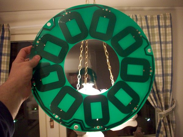
KF, have you thought of a stator solution with PCB's ? The one on the picture is 780 µm thick and contains 140 gr copper. They can be stacked in unlimeted number.
a2.jpg


/Göran
 
After sleeping on the air gap between adjacent magnets (Agm), I would like to add another diagram in hopes of crystalizing the issue for better comprehension:

Fig-8.png


In Figure 8 we have two Magnetic Arrays; if these are of Halbach design, the flux density (Ф) on the left will vary and weaken as the radius from the center expands, while the one on the right should remain consistent - at least in the ideal sense. We can likewise observe that the air gap widens on the left (left dimension), whilst the air gap on the right is consistent.

Conclusions:
  • The Left array could benefit if the air gap was filled with more permeable material such as electric steel because it would condition and spread the field strength as the radius expands towards the OD. See Figure 1.
  • The Right array does not require filler material since the geometry already propagates the desired affects.
  • If the Left array requires filler material, does this material need to touch the adjacent magnets?
  • What is a reasonable ratio of air gap to adjacent magnet?

I think once we get this resolved we can return to the windings aspect.

Thud: Oh gosh, I’ve read and re-read your posts on the subject, and searched and plumbed the depths of ES on various aspects in the quest to comprehend this quirky twisty AF solution. The question I have for you is:
  • When you asked for bids on the custom design of the shape, were you daunted by the quote or quantity? Can you briefly outline the issues that you faced? Perhaps together as a team we can overcome this, yes? :)

Goethe: Yes, a PCB stator has been conceived as one way to accomplish the windings. LFP has the same recommendation. We need to evaluate the characteristics of the windings relative to the flux density and the expected torque before evaluating which is the best approach to packaging. BTW – that is an awesome pic of a PCB stator! Where did you get that? I can easily imagine a multilayer heavy-copper board. Can you imagine though the torque upon the trace face when going WOT? I wonder how thin we could make an internal layer?

Winding Material:
OK – I’m taking the plunge. Have you guys considered the multipath Litz wire to reduce eddy currents? I am imagining the Hz becoming something like 7 rps * Teeth/Phase-Count and then multiply that by how much faster than [30 mph/ 48,3 km/h] we wish to go. Therefore…

Solve for frequency (f) if the number of poles-pairs is 20, and the number of teeth is 21 for a 3-phase motor at 7 rps:
  • f = (21 teeth / 3 phase) * 7 rps = 7 * 7 = 49 Hz (previously solved on Sat Sep 11, 2010 12:38 pm).
If I want to go 1.5X faster then f would need to be 1.5 * 49 = 73.5 Hz. Nothing here suggests fear of eddy currents from high frequency. The part that is missing is how fast we need the microcontroller to pulse the FET stage, and I don’t have an answer to that.

Regardless, I think it’s worth evaluating all the winding options, and to do that we need to calculate the turns per winding next. :)

Best, KF
 
Kingfish said:
Understood. Neat FEA pics; did you make those?

Yes, using a software package called FEMM. It's freeware and very useful for this sort of thing. It does require a little bit of knowledge to use, but they provide a few helpful tutorials and I believe more info can be found on the web.

I'm not really sure what pole shoes are, but Google seems to tell me that's referring to the wider "face" part of a stator tooth. I don't think that's applicable here; as you say I think it would tend to divert the flux in a non-useful way.

Talking of air gaps, spacing, and so forth:
The important bit to understanding here is to draw and visualize the complete flux circuit. In the Halbach case, you already drew the picture:
Kingfish said:
Fig-7.png
You got it right here, although the arrows going from rotor-to-rotor are in the wrong direction (should be N-to-S). If you draw them in the correct direction you can easily see the circulation patterns that are set up. The total reluctance around that path determines the flux that flows. Just like V=IR, here we have F=R*phi, where F is called magneto-motive force (MMF, script F), R (script R) is reluctance, and phi is the flux. R for magnets and magnetic materials is very low, R for air and non-magnetic materials is very high. The flux path flows from S-L-N and N-R-S through the adjacent magnets, so any spaces here which are not filled with magnetic material will increase R and thereby decrease flux.

In the non-Halbach case, using regular N/S magnets and a flux ring, now the flux path flows down one magnet, through the flux ring, through the next magnet, across the stator and so forth. Now the flux ring is carrying flux from one magnet to the adjacent one, so a gap between magnets does not increase R. In fact, as discussed earlier, we want to have some spacing here. Tracing out the path lets you see which gaps are bad and which gaps are good (or neutral).
 
The PCB stator is a slick solution, but power handling would be limited I think. FR4 is a lousy conductor of heat. If you stacked multiple boards you'd have to leave an air gap between or the inner layers would be very effectively insulated. You'd face the same problem using the inner layers on a multilayer board. Also, even if you used 2 oz copper, the traces are pretty thin so they'd need to be wide to have a reasonable resistance.

I think it'd be great for a small, low-power motor, but probably not well-suited to something for high-power. I remember this was discussed here previously but I don't remember if there were any other pluses/minuses brought up.
 
Flux, Air Gaps, Reluctance…

Fig. 7:

Fig-7a.png


Corrected; I thought it was off. Thank you! :wink:

Fig. 8:
  • OK, so if these are NOT Halbachs then we’d have to use a high-permeability/low-reluctance back plate, and air gaps are not a large factor – in fact we want some gaps; gotcha.
  • But if they ARE Halbachs, then we want them to touch, or fill the void with high-permeability/low-reluctance material.

If I have this correct, let’s call this section done, finished, baked, closed. :D
Thanks, much appreciated KF
 
Cool. We’re baby-steppin’ makin’ progress 8)

Halbach and Windmill magnets - Compare/Contrast on Mass:
Thud brought up a good point on the mass and I wish to run a quick review. Given Figure 7 – Right side, let’s presume that we have two arrays, one Halbach and one Windmill, and that the total pole counts are the same as is the Tesla rating.

  • Windmill requires an attached plate or permeable rotor to complete the magnetic circuit, and Halbach does not.
I would wager that by virtue of the elimination of the backing plate the Halbach array will be lighter. Without physical evidence we can’t be certain, however as much can be inferred by review of Shane Colton’s thesis and looking at the relatively thick steel plate. Aluminum in the 70-series has similar strength properties to steel alloy given slight dimensionality adjustments, however the weight is significantly less, perhaps as much as 40% less. I like not having iron in my motor, and I wouldn’t have any at all – except for say… for the bearings. This is the motor I wish to build.

Teeth and Poles:
The Windmill magnets commonly available would allow for Qty-16, or 8 pole-pairs/8:1 gearing. This likely would translate to a low-voltage high-current fast-spinning rotor. In contrast, my 9C 2806 has 51 Teeth, & 46 magnets/23 pole-pairs/23:1 gearing. This motor will consume about 2 hp to push me up a steep hill at 30 mph/48,3 km/h. I want to craft an AF design that re-creates that experience – and then improve upon it by making it go faster with the same amount of power.

  • I studied the Wiring Diagram here http://fast-results.com/lnl/nutpol_e.htm
  • In addition, I played around with the Motor Winding Scheme Calculator and developed a spreadsheet that was quite revealing.
Observation: The most optimum Teeth/Pole-Pair ratio follows this pattern…
  • Teeth/Pole-Pair ≈ 1:1 where
  • Teeth/Pole-Pair ≠ 1, and
  • Teeth/Pole-Pair ≠ integer, and
  • Pole-Pair/Teeth ≠ integer, and
  • Teeth = (Pole-Pair +/- 1 or 2)
Here is a wiring diagram that estimates beyond 18 Teeth & 20 Poles given previously for up to 36x36:

WiringDiagram.36x36.png

Wiring Diagram for optimum Teeth/Poles up to 36x36

My Plan is to shoot for 20 Poles and 21 Teeth, 3-Phase. This is not set in stone; we can change it – though we have to start someplace, yes? :)

Questions?
~KF
 
KF,
If your going to attempt ironless, i see no reason not to follow the leaders in the feild. they have been very generous in documenting some of their "secret sauce" in their version of dual Halbach arrays in axial motors
http://www.launchpnt.com/Documents/halbach-electric-motor-slideshow.pdf
still spinning fater than your goal from my observations...but that may be addressable....to a degree.

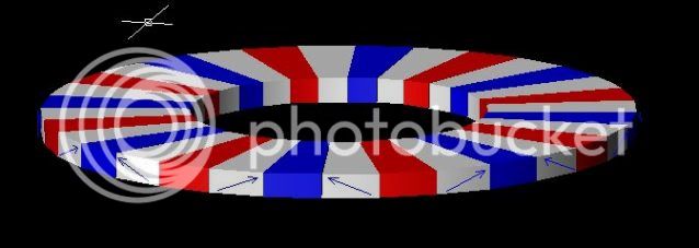
i did a simpler take-off of single halbauch aray & went with 16 poles (before you posted your ideal senario) it looks a little like this:
AXIALHALBACH.jpg


notice i have the pole askew on the intermediats....this may or may not have any real effect.....perhaps FEMM would tell us more....need to search for that.

I contacted KJ magnetics for a quote but that info is long gone...it was over my budget by 10x & I don't recall the exact #s.(something like 2k$ for custom wedge molds & multi set ups for biased magnifcation & min orders)

Also, where is Madact's input in this exchange? he is on the same path:
http://motoredbikes.com/showthread.php?t=27658

I can resubmit a RFQ & see where the #s come in....tell me a diameter & thickness you desire, I will model it & send it through for quote. & copy the info here. we'll see if it a reasonable enough request for board sponcership.
Thud
 
Thanks Miles,
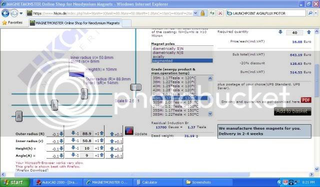
that a nice site & a lovely way to order special magnets....I ran a quote for some mid range magnets to do the 20 single halbauch....
178mm od x 50.8mm id. 9deg x 40 segments (I asume aposing magnet arrays so X2)

The conversion comes to roughly $1338.00 USD before shipping costs. The lead time is reasonable also. if i were totaly commited to building an ironless motor with a halbach array....i may be able to justify that cost. but not in the forseable future. it would be fun to build a motor utilizing the configuration though.
20POLEH2.jpg
 
This seems like an opportune time to point out that you could use other magnet shapes to build a (non-Halbach) high pole-count rotor. I've seen a few designs using circular puck magnets, I think rectangular magnets would work fine as well. Choose size to suit your desired pole count and diameter. A flux ring would be required.

Tossing another wrench into things, have you considered that axial flux machines can be "stacked" for higher power? Instead of your R-S-R configuration, you could add another rotor and stator to make it R-S-R-S-R (extend as far as you like). I think that would pretty much double the power/torque. Since the two stators could be wired in either series or parallel, you could even put in a switch to get two different Kv's.
 
Thud:
Yeah, I expect the 10:1 ratio to be too fast; I just need to make a stab at it, run through the calcs, and build a worse-case scenario. I have seen that LaunchPoint presentation before in the hunt for information. Thanks for putting that back in front of me; it’s good for review. :)

In reference to that doc, I am going to pass on the 45*F flux pieces; that doubles again the part count. Did you note how they were cooling it with the baffled separator between the rotors? I had a similar design drawn up weeks before seeing theirs. Also they are using the adjacent coils where I do not plan to do so; the power requirements are lower for my design; no need to go higher than 5 hp on race day unless we introduce LN, right? :D

The Plan is to have only two orientations for wedge-shaped, or one orientation for bar, then flipping as prescribed. I have a good impression of the bar cost but the wedge is more interesting. The OD will probably be similar to the 8” Windmill, though I may opt for higher ID to keep the mass down. Let’s evaluate for moment the 9C 2806 magnets:

3 x 13.5 x 27 mm. I am guessing they are N45. LFP said someone on ES had a Gauss meter and they could measure. Let’s just said for conversation that I’ll use the same. The dimensions will be 6 mm thick and slightly longer. With two rotors we’ll have twice as many poles - though our radius arm will be a little less because we are axial not radial. Though comparing apples and oranges, I still expect the torque to be greater and the motor to be more efficient.

Budget: Man if someone quoted me $2k I’d get put-off too. We have to do better.

Thanks for sharing Madact's thread; it was very interesting; lots of user-experience there worth noting. The FEMM software I downloaded had a Trojan attached; it was trapped and deloused, but I haven’t got back to it.

Miles:
Wow what a neat wizard – and with instant quotes! Thanks man, I’ve added that to the Magnetic Wire & Nd Magnets Reference. :)

Eric:
I am committed to doing Halbach, however I think it would be prudent, prudent (fingers pointing), to have a Plan-B with the traditional bar magnets in parallel. :)

Multiple Rotor-Stators: Oh yes, that was conceived for the next motor such as a single gear rear hub. If you get rid of the disc brake you can fit two stators in the front hub. What are the distances between mountings for endure-class motorcycle? I’d think we’d be able to do two stators in front and three in the rear. It’s got to be modular construction though; Kingfish idiot-proof assembly.

~KF
 
Back
Top