Commuter Booster - <1kg Friction Drive

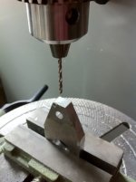
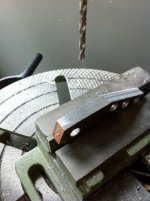
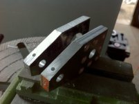
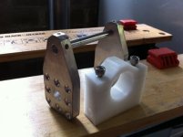
And a new side plate for the bearing side.

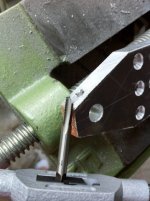
Note what happens when you guess the drill size for a tapped hole... a broken tap. :x

IMG_1219.JPGView attachment 5IMG_1223.JPGIMG_1224.JPGIMG_1226.JPGIMG_1227.JPG
 
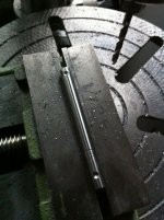
Dimple the shaft to take the torque to align the side plates.

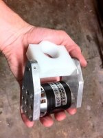
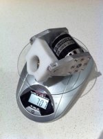
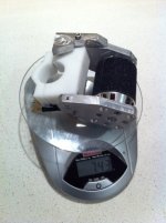
Throw it together, chuck it on the scales..... and ......

707 grams or about 1.5 pounds. :D

Still need to add a few deadstops etc. But not bad.

IMG_1240.JPGIMG_1231.JPGIMG_1250.JPGIMG_1251.JPG
 
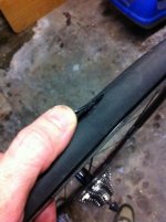
Next step, get it on the bike and spin her up . But ....arrggghhhhh... a major flat and tire failure.
I just rode the bike to work yesterday. Inner tube must have let go, and blown the tire out over night. :x

Will have to get a new tire tomorrow.

View attachment 1

IMG_1241.JPG
 
I really like your tube-clamp a lot! It would also be useful for battery enclosures, or any other frame-attachment problem. I really appreciate you showing the progression of how to make one, so that the two bolt holes are in perfect alignment. Great work! The design is very elegant and simple.

If someone had an oval or triangulated tube cross-section, you can fill the void with JB or Devcon (putting grease/wax on the frame till it dries, do one half of the clamp one night, the other half the next)

I broke a small drill bit a couple months ago (I have also broken small taps in the past) and based on an Endless-Sphere suggestion I recieved, I put it in boiling water, and the aluminum expanded more than the steel.
 
Good work Adrian. Lots to like about your solution. I especially like the low parts count, something i am working really hard on at the moment with my drive.

The clamp looks good. Nice and simple and I really like how the clamp becomes the the pivot bearing. What type of material is it? I wonder how the tapped threads will go in the clamp? Need to put a fair bit of pressure on the clamp to keep it in place so I hope the threads are up to it.I am sure we will soon find out. If they don't hold, you always have the option of making the clamp wider and drilling the clamp hole right through above the pivot shaft then using nuts and bolts.

No road testing in sunny Melbourne today :(
 
Kepler said:
Good work Adrian. Lots to like about your solution. I especially like the low parts count, something i am working really hard on at the moment with my drive.

The clamp looks good. Nice and simple and I really like how the clamp becomes the the pivot bearing. What type of material is it? I wonder how the tapped threads will go in the clamp? Need to put a fair bit of pressure on the clamp to keep it in place so I hope the threads are up to it.I am sure we will soon find out. If they don't hold, you always have the option of making the clamp wider and drilling the clamp hole right through above the pivot shaft then using nuts and bolts.

No road testing in sunny Melbourne today :(

Yeah. Time will tell.

The clamp is made of acetal, with M6 clamp screws with about 15mm of engagement.
I might need the relieve the bolt region from the pivot region in case the pivot hole is distorted with the load. If I do this I could put a nut in the relief slot easily enough.

But I will wait and see how dead stops and springs work out first. As I think that will change the shape a fair bit depending on which version I end up using.
 
A few updates:

1) Dead Stops/Travel Limit Stops, done
- motor no longer slams into the seat tube, or seat stays.

2) Torsion Spring, built and tested
- I now have a torsion spring around the main pivot, that takes most of the weight of the motor.
- it needs to be a little bit stronger, but it was the best spring option I had on hand.
- This means only a small start torque is required to lift the motor in to engage the wheel

3) First Test ride , DONE !!!!!!

Good news:
- clamp didn't slip
- pulled 1000W
- nothing blew up

Bad news:
- torsion spring too weak, and can't wind it any tighter as it is starting to lock out on the shaft. So the motor wasn't picking up properly.
- motor was slipping on the tyre.

Next steps:
1) tune torsion spring
2) improve motor to tyre grip
3) tune the mounting position again, with new spring/grip set-up
3) play with soft-start


Actually, thinking about it I might be able to used two springs, one on the other side.... hmmm off to the shed to have a look. And take some more update pictures.
 
Here are a few pics to show the new travel limits, and torsion spring.
Rough but good enough to test out.

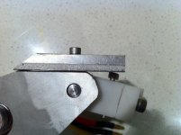
Pic #1:
- shows the new travel limit to stop the motor smashing in to my seat stays.
- Screw allows adjustment
- this can easily be integrated into the side plates, and main pivot block for the next prototype.

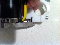
Pic #2:
- shows the new lower travel limit to stop the motor smashing into my seat tube
- the screw is what hits against the new recess in the main pivot block.
- it also secures one end of the torsion spring.
- the other end of the spring tucks into a radial hole
- as it is a fairly soft spring, you can only adjust in in full revolutions of preload at the moment.

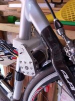
Pic #3:
- show the whole thing on the bike.


Video coming soon... :D

IMG_1264.JPGIMG_1265.JPGIMG_1260.JPG
 
Bench Test #1

2s 1300mah Turnigy LiPo
[youtube]L_mPArb2018[/youtube]
 
adrian_sm said:
Note what happens when you guess the drill size for a tapped hole... a broken tap. :x

Hi, FWIW, if you mean that you didn't know what size to drill, metric threads are dead easy to remember: it's the diameter - pitch eg M6 1.0 pitch tapping size is 6-1= 5.0mm. If you mean you knew that but guessed the drill size, measure the bugger next time :lol:

Like the drive

Cheers,
GT
 
Bench Test #2

6s 5000mAh 20C Turnigy LiPo

[youtube]w79wNBCy5G8[/youtube]
 
gtadmin said:
adrian_sm said:
Note what happens when you guess the drill size for a tapped hole... a broken tap. :x

Hi, FWIW, if you mean that you didn't know what size to drill, metric threads are dead easy to remember: it's the diameter - pitch eg M6 1.0 pitch tapping size is 6-1= 5.0mm. If you mean you knew that but guessed the drill size, measure the bugger next time :lol:

Like the drive

Cheers,
GT

Thanks GT. I was just lazy. Picked up a bit, eye-balled it against the screw, and thought she'll be right.... :roll:

I might take two seconds next time, and remember "metric threads are dead easy to remember: it's the diameter - pitch". Thanks.

Adrian
 
Looks great so far! So small and light.

What are the no-load speed and current?

Careful of squashing those butted Al tubes, could always make the clamp wider to distribute the load.
 
Thanks mate.

I am loving the light weight, only about 1.5kg, including battery, controller, drive everything, added to an already light bike.
You totally forget it is there. So different to the usual ebike that weighs in around 30kgs, and you try and avoid having to pick up.
This one still feels totally like a normal bike. :D

Haven't looked at no load speeds, as speedo is on the front wheel at the moment. Based on kV and 6s, should be up around 50-55 kph.

No load power was (from memory) about 20w for 2s LiPo, and if I fully engaged the motor by hand, to simulate the full loaded rolling friction, I think it was 50w. But this was with huge amounts of motor engagement into the tyre, and I may have totally got these numbers wrong, as I had had a few beers at this time, and my memory isn't great at the best of times.

And this was really quick and dirty tests, without tuning the amount of engagement, and really should be done at 6s LiPo once I get the friction, geometry, and amount of engagement all tuned.

I think the most important thing to get the no-load losses down is to get the motor to tyre friction better. This means less pressure is required, which means less tyre deflection, which means less rolling friction. Well that is the theory any way, we will see how it goes in practice.

Next challenge will be the throttle, at the moment I just have the servo controller taped to the top tube. :shock: Way to dangerous, once I get the drive engaging properly. Bit like setting cruise control in the car, but putting the controls in a really non-intuitive location. So if you need to turn it off in a hurry, you brain just can't react quick enough. I have images of that guy that got stuck in his car without being able to override his cruise controll.... :lol:

At the moment I am thinking of have a normally open button up at the handle bars, adjust the controller for a soft start, and leave the servo controller some where handy to tune speed. So you have to hold the button down to engage the throttle. This should do for testing, then I can work out a more permenent/user friendly solution.
 
full-throttle said:
Careful of squashing those butted Al tubes, could always make the clamp wider to distribute the load.

Not too worried. It is clamping on the entire circumference, no point loads, and the seat-tube would support things on the inside if you got crazy. But to be honest it isn't clamped down that tight.

Thanks for the warning though, I'll probably crush it and then you can tell me I told you so. :D

- Adrian
 
..and being made of plastic won't even damage the paint, right?

Your friction drive is a very elegant and simple alternative. What are you going to do against the road grit ingress?

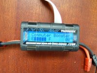
BTW feel free to borrow the throttle interface, it works with both pot and hall throttles AND the code now runs on the Turnigy meter which is extremely easy to hook up to throttle, making it an inexpensive monitor at the same time. Here's a teaser ;)CBM1.jpg
 
full-throttle said:
..and being made of plastic won't even damage the paint, right?

Your friction drive is a very elegant and simple alternative. What are you going to do against the road grit ingress?

BTW feel free to borrow the throttle interface, it works with both pot and hall throttles AND the code now runs on the Turnigy meter which is extremely easy to hook up to throttle, making it an inexpensive monitor at the same time. Here's a teaser ;)

Sounds cool will have to give it a go. Will it work on this turnigy watt meterhardware?

As for road grit. I'll let it run with no protection at first to see how it goes. Then add protection later if needed. Got an idea on how it can be done neatly. Might use the same mounting features as future hall sensors.
 
file.php


Man I should stop posting from my phone. I missed the text on the screen 8) , and that it is identical to my turnigy meter. Awesome work. Too cool.

Update:
Dropped off at Bunnings and picked up some no-name anti-slip tape.
$7 for 5m. That works out as 22 cents for per motor. I can live with that.

 
full-throttle said:
What are the no-load speed and current?

Just did a quick test at 6s, with anti-slip tape on the motor.

The amount of engagement into the tyre makes a huge difference. On the second try with a smaller amount of engagement was up around 150W. Then I applied the brake and saw about 1000W with no slip.
Lots more tuning to do.

I also weighed all the parts for a complete drive system.
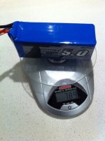
789g - 6s 5000mAh LiPo
743g - Commuter Booster Drive
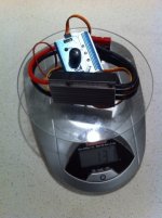
131g - 85 Amp ESC + Servo Tester
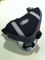
107g - Little frame bag to hold the battery

Total weight for the whole system 1771g, or 3.9 pounds.

Not bad for something putting out a 1000 watts. :D

IMG_1289.JPGIMG_1288.JPGIMG_1290.JPGView attachment 1

It all manages to fit in the little frame bag too.
IMG_1292.JPG

- Adrian
 
Hillhater said:
Adrian,
have you tried testing it with a load on ( brake ).
.. curious to see if you have any sync issues :wink:

Sorry missed this, before.

No real data on sync issues yet.


My only onroad tests so far were before the grip tape, so when I hit the throttle too hard the motor would tend to slip, rather than lose sync.

I have the grip tape on now, seemed to work well in the shed when applying the brake. But I had the wheel going pretty quick, then applied the brake. I believe it will be more of an issue at low rpms, when you suddenly hit the throttle. The road test should defeintely show this up, but unfortunately family and work keep interupting testing.
 
Just had full-throttle drop by my desk at work, and tried a throttle interface he has built. Very nice work.

This would allow the use of a hall or pot throttle, or he said you can use up/down buttons.
You can see his creation at the bottom of screen in this little video of one of his bench tests a while ago.
[youtube]hlJR9A6VWTY[/youtube]

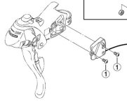
But the big problem is on a road bike there is no nice place to put a typical throttle. I was toying with the idea of using momentary buttons somehow/somewhere, and noticed that my Shimano control levers have little button moldings in the grip region. Full-throttle said these are for the Shimano Flight Deck bike computers.

A quick goodle search later, and here is a picture from a shimano manual, that shows the location of one of the buttons, and the hardware you can buy.
Shimano Flight Deck Buttons.PNG

This looks promising. I might be able to install a couple of buttons discretely in existing hardware, in a pretty damn good ergonomic location. Great for me, not so good for anyone without these control levers.

Question is what the button logic would be. Maybe use these to increase/decrease speed, and a momentary switch that must be held down to go.


Good food for thought, but must get the mechanicals sorted first.
 
That is a great idea, for a booster all you would really want are maybe three different throttle positions: off, hi speed, lo speed. Adrian, you are designing a brilliant drive, and super stealth. You could probably tell a cop it powers a light on your handlebars and he wouldn't think twice IMHO. That would help you get by the ridiculous watt limit you guys have there. :roll:
 
Back
Top