Simple ebike 'fuel gauge'

Oh no not another project I must start!!! Very Very cool, I was looking to do something similar my self since I was finding nothing on the market that could pull this off inexpensively. Thank you very much Jeremy for putting this up and sharing with everyone :D PS where did you get that rocker switch that is in the photo near your throttle in the first post?
 
magudaman said:
Oh no not another project I must start!!! Very Very cool, I was looking to do something similar my self since I was finding nothing on the market that could pull this off inexpensively. Thank you very much Jeremy for putting this up and sharing with everyone :D PS where did you get that rocker switch that is in the photo near your throttle in the first post?

Thanks for the kind words.

The rocker switch came with the bike, it was an ebay buy, the details are in this thread: http://endless-sphere.com/forums/viewtopic.php?f=6&t=21945

I've seen similar switches on other ebikes, so I'm guessing that they are a generic Chinese part. I've not seen a supplier of them yet, though.

Jeremy
 
Alright I have been working on my own version of this little circuit for the last week but have changed the code quite a bit to allow for up to 30ah packs and would be independent of the controller. I am using a hall effect open loop current sensor to give the current readings. I would really like to add an LCD display to just interpret serial and give a percent and a fullness gauge. Since I have ditched the voltage sense part of the circuit I do have an extra output line. Is this within the capabilities of the 08, I do see that it can only do 4800 baud out the serial connections and all the cheap lcd units I see only have 9600 baud.

I was thinking about dropping the average current sampling rate to 50 so I can save to eprom each round so users can shut down at any time. Is there enough time in a cycle for this in your experiences?

I see that you dump out a calibration pulse but how did you actually interpret that and calibrate your setup?

I am also trying to get a consistent 5v and picked up some linear regulators that are good from 20-125v. So far in testing them they are consuming about 1.3 watts while my 5v output is only needing 0.075w. Is there any more efficient way to get 5v at such low power levels?

Thanks Jeremy again for this great project!
 
magudaman said:
Alright I have been working on my own version of this little circuit for the last week but have changed the code quite a bit to allow for up to 30ah packs and would be independent of the controller. I am using a hall effect open loop current sensor to give the current readings. I would really like to add an LCD display to just interpret serial and give a percent and a fullness gauge. Since I have ditched the voltage sense part of the circuit I do have an extra output line. Is this within the capabilities of the 08, I do see that it can only do 4800 baud out the serial connections and all the cheap lcd units I see only have 9600 baud.

The only two serial displays I've driven from this chip are the AXE003 from the Picaxe people and the Cat's Whisker Textstar display that's in this thread: http://endless-sphere.com/forums/viewtopic.php?f=2&t=14498 Both work OK from any output pin on the 08M, in my experience.

magudaman said:
I was thinking about dropping the average current sampling rate to 50 so I can save to eprom each round so users can shut down at any time. Is there enough time in a cycle for this in your experiences?

I think it should work, the reason I only write to eeprom every power shutdown was just to limit the number of write cycles to it, but the reality is that it should last a long time even if writing to it once a second. There should be time for this, you just need to adjust the pause values (coarse adjustment inside the repeated measurement routine, fine adjustment in the loop) to get back to 1 second (or whatever value you choose to use) for correctly calculating remaining capacity. In practice the shutdown routine very reliably detects power off and saves data in plenty of time before the power supply dies. If you wanted to make it independent of the controller, then adding a bit of capacitance to the supply will hold it up for the very short time that the Picaxe needs to save and shut down.

magudaman said:
I see that you dump out a calibration pulse but how did you actually interpret that and calibrate your setup?

I hooked mine up to a USB 'scope, looked at the calibration output pulse edges and adjusted the two pauses to get as close as I could to 1 second between them. I managed to get mine to 999.8mS, which was plenty good enough. You could do the same with a counter/timer hooked up to this pulse, or even set it very roughly with a LED on the output and a stop watch.

magudaman said:
I am also trying to get a consistent 5v and picked up some linear regulators that are good from 20-125v. So far in testing them they are consuming about 1.3 watts while my 5v output is only needing 0.075w. Is there any more efficient way to get 5v at such low power levels?

What's really needed to do this efficiently is a switch mode regulator, but they are hard to find at these high input levels. LFP pointed out in the simple controller thread that there are some cell phone chargers around that do the job, maybe gutting one of these might get you what you're after. If you can cope with a lower input voltage, then I think johnrobholmes has some for sale.

Sounds like you're having fun with this, I look forward to seeing how it turns out.

Jeremy
 
One thing that you should do to extend EEPROM life in micros is first read the EEPROM value and compare to what you want to write. If they are the same, don't bother writing it. Very simple, very obvious, and for some strange reason it is seldom done. I know of one commercial product was killing its micro in under a month because of this very issue.

Another useful thing to do is after reading or writing an EEPROM location or page, read an EEPROM page that is not used by your code (for several reasons the page starting at address 0 is usually best... i.e. some micros are know to corrupt this page). This will leave the EEPROM address pointer pointing to unused data. This will minimize the chance of useful data being corrupted during power cycles/glitches.
 
texaspyro said:
One thing that you should do to extend EEPROM life in micros is first read the EEPROM value and compare to what you want to write. If they are the same, don't bother writing it. Very simple, very obvious, and for some strange reason it is seldom done. I know of one commercial product was killing its micro in under a month because of this very issue.

Another useful thing to do is after reading or writing an EEPROM location or page, read an EEPROM page that is not used by your code (for several reasons the page starting at address 0 is usually best... i.e. some micros are know to corrupt this page). This will leave the EEPROM address pointer pointing to unused data. This will minimize the chance of useful data being corrupted during power cycles/glitches.

Good tips. It the obvious things like this that are so dead easy to miss. In my case it only writes to eeprom on a power loss event, where the value will almost certainly have changed since the last save, but it might still be worth doing the check I guess, as it doesn't take any headroom, that code is only run at power on.

For the "save every second" idea then it'd be a great saving in write cycles, because I bet that a lot of the time the bike is powered up it's not drawing any appreciable power (stopped at junctions, powered up but no moving while you get on/off etc or even just free wheeling down hill).

Jeremy
 
I definitely am having fun with this stuff! It's pretty awesome learning how to code these little beasts and really seeing how powerful simple code like this can be. My mind starts to swirl with all the idea I can make possible so easily now with just simple programs.

Any how I did the math and saving each cycle doesn't seem like a good idea at all. It appears I would burn up my 100,000 writes in something like 27 hours?!?! SO, maybe I will go back to using your voltage line sensor on mine to do the saves and get that figured out.

I checked out that textstar LCD and that is a very cool module but they are quite pricey at about $45usd! They do save you from having to do the graphing code though which proves to be pretty darn nice. I just might have to pick one up. It would be pretty cool to be able to show a fuel gauge, percent remaining, and current with no display changing.

You mentioned the switch mode regulator and I cringed a bit since I know I am not able to build on my self and usually prove to be quite expensive if purchased in a DC-DC form (new that is). And since I wanted to keep the costs down for this project and keep the possibility of small scale production for members I thought that was out. But then I did remember I can get those switch mode Ipod supplies that measure about 24x24x24mm and provide up to 500ma at 5v for something like 3usd. I figured I would crack one open and hook it up to DC. Sure enough good to like 15v dc and seems to regulate pretty well to 5.34v just varying by 7 thousands. The unit seems to consume about .125w + the load so it sure beats the linear regulators

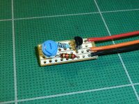
Here are a couple crappy photos:

img1722vd.jpg


img1721w.jpg
 
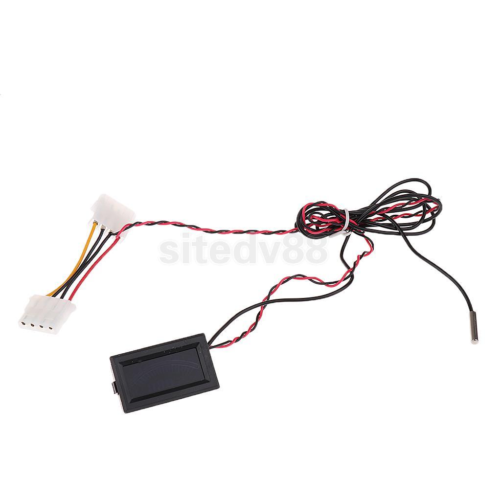
Regarding cheap and effective display options, could these units be employed?
image.jpg

Price is about $9 (inc post):
http://cgi.ebay.com.au/Digital-Thermometer-Temperature-LCD-Module-Gauge-C-F-/110627111029?pt=AU_Gadgets&hash=item19c1e3c075#ht_2367wt_918

Just cut off the sensor and feed it a (biased and scaled) analogue voltage?
The numerical display and scale (-10 to 80C or the F equivalent mode) wouldn't be so helpful, but could simply be masked to leave the 19 segment LCD dot graph.
Weather proofing would also be required.

BTW, I'm a long time fan of your work here on ES Jeremy!

- Ben
 
BenMoore said:
Regarding cheap and effective display options, could these units be employed?
image.jpg

Price is about $9 (inc post):
http://cgi.ebay.com.au/Digital-Thermometer-Temperature-LCD-Module-Gauge-C-F-/110627111029?pt=AU_Gadgets&hash=item19c1e3c075#ht_2367wt_918

Just cut off the sensor and feed it a (biased and scaled) analogue voltage?
The numerical display and scale (-10 to 80C or the F equivalent mode) wouldn't be so helpful, but could simply be masked to leave the 19 segment LCD dot graph.
Weather proofing would also be required.

BTW, I'm a long time fan of your work here on ES Jeremy!

- Ben

Thanks for the kind words, Ben.

To be honest, I'm not sure if those displays could be made to work or not. It'd be neat if they could, but it all depends on what sort of sensor they use to measure temperature. If the meter can be adapted to accept a voltage input, then the simple answer is yes, they could be made to work. I guess the answer would be to get one and experiment with it to see how it works.

Jeremy
 
I found the problem with a lot of the true or digital analog gauges is there voltage ranges are a little crazy or rely on power and then different ohms (like car fuel gauges). I have been messing around with a couple alternatives and settled on just using 3 led directly driven from the picaxe. Since all my inputs and outputs are tied up I decided to give the circuit a given current and timed it to calibrate the unit.

Here was my earlier idea prototype which could still be used, and these sub micro servos can be as cheap as 4 bucks:

[youtube]zMYxd204uRI[/youtube]

The 3 LEDs actually gives the equivalent to 6 positions of remaining capacity, I got the code all done and just need to put it on the battery to do the final testing. This is how it works:

fuelguage.gif
 
I have found the lipo V indication that I have incorperated very useful and am now thinking along the lines of the above post i.e just use maybe 2 leds for battery capacity and keep the 2 leds for battery voltage. I have not used the current indicator at all so I think I will now like to drop the 10 bar led display that Im am using ( which do work very well by the way ) . Im all for trying to keep it simple. We shall see :D
 
Ok so I decided to go to the 10 segment led display for my unit after seeing how simple the LM3914 type unit is but have run into an issue. It seems that I ended up with a PWM output range of 155 to about 280. I have the equation setup so it sweeps that range based on percentage and is calibrated. But the new issue seems that my lm3914 is not very linear. It shows about 50 percent at about the 70% mark but then slows down end correctly when expected. I did have to use a capacitor to filter the PWM output so the display wouldn't go crazy.

I also just created a quick sweep program and can see it spend more time on the lower value leds then the upper ones.

What gives any ideas?
 
magudaman said:
Ok so I decided to go to the 10 segment led display for my unit after seeing how simple the LM3914 type unit is but have run into an issue. It seems that I ended up with a PWM output range of 155 to about 280. I have the equation setup so it sweeps that range based on percentage and is calibrated. But the new issue seems that my lm3914 is not very linear. It shows about 50 percent at about the 70% mark but then slows down end correctly when expected. I did have to use a capacitor to filter the PWM output so the display wouldn't go crazy.

What gives any ideas?

Have you used any pd or have setup the input to the lm chip at all ?. I just ran the filtered PWM signal straight into the chip ( I think from memory it was about 0-1.2v fsd ), I cant say as I notice this non-lin on my one. I have since changed it, and now only use one led to indicate low capacity ( off/on and flash ) and 2 other leds to indicate battery voltage ( blue(on/flash then off) red (on/flash), I personally find the voltage indicator more use than the other functions.
 
gwhy! said:
Have you used any pd or have setup the input to the lm chip at all ?. I just ran the filtered PWM signal straight into the chip ( I think from memory it was about 0-1.2v fsd ), I cant say as I notice this non-lin on my one. I have since changed it, and now only use one led to indicate low capacity ( off/on and flash ) and 2 other leds to indicate battery voltage ( blue(on/flash then off) red (on/flash), I personally find the voltage indicator more use than the other functions.

Yes I did set it up for a different range but took that out just for one less variable. I was trying to get 0 to 4v so I used a 1.2k resistor for the led current and 2.2k for the range. So with only the 1.2k resistor I end up as you said a 0 to 1.2v range (according to spec sheet) but it seems that to pulse that out of the chip I set it up to pmwout 2, 99, (100 to 240). What's odd is 100 calculates to 25% and 240 to 60%. ARG still isn't linear, maybe its an issue with the size of my capacitor?
 
ok it has something to do with the way I am filtering the PWM. I didn't have any resistors on the output just the cap. It seems that I should use the cap in parallel (as I was doing) but put a resistor in series with the output pin to the lm3914. This will properly do the filtering. Ok well I need to play some more but I think I am done for the day.
 
I am moving my intended project of Jeremy's PIC power indicator with linear LED display further into infinity, but I need now at least the indication of voltage of the battery. The original LED indicator on the twist throttle is in a good position, is for 24V lead battery and cannot do much on my 40V Lipo's as it is. So I have made a little scale shifter with low impedance emitter follower and voltage divider to drive the existing LED display. 32V on Lipo translates to 20V on the indicator, showing "Empty" and 38V refers to 24V "Max" all LED's on. It is not exact approximation on the Max. voltage, but the most important "near end" low voltage is shown well.
 

Attachments

  • LED indicator driver.jpg
    LED indicator driver.jpg
    102 KB · Views: 3,513
otas said:
It is not exact approximation on the Max. voltage, but the most important "near end" low voltage is shown well.

Nuthin' a couple of 32 bit microcontrollers can't sort out...
 
Exactly, but I wanted to KISS - keep it simple s... LED's will start dropping off after approx 70% remaining power, which I think is acceptable. For me at least...
 
otas said:
Exactly, but I wanted to KISS - keep it simple s... LED's will start dropping off after approx 70% remaining power, which I think is acceptable. For me at least...

I'm not sure that this will really be the case. I did something similar to lower the trigger voltage of the LEDs on my throttle (I just used a series resistor, as it turns out that the current variation as the LEDs turns on isn't that great) but found that the indication wasn't that reliable. I was running on a pack of Headway LiFePO4 cells at the time, that tended to sag a bit more then LiPo under load, but one thing I noticed was that the LEDs tended to drop as the power came on then recover back at lower power settings. Leaving the bike off for a few minutes would restore the "full power" indication as the cell terminal voltage recovered, even when I knew that the battery pack had to be close to being fully discharged. Trying to interpret the voltage drop under load with the battery charge state was difficult, which is why I opted to build this meter instead.

Jeremy
 
It's a bugger that you blew a couple of chips, but nice to see another one working!

Jeremy
 
Wow! This thread is growing fast. Serves me right for not watching it recently!
I am also working on a derivative of this meter, with a 16x2 LCD to give me a bargraph, and numeric readout. I realise this is straying from the the purity of Jeremy's original concept, and I have wondered about making a KISS version, by using an LED bargraph as the Ah meter. Right now the risk is that I am just reinventing the cycle analyst meter ;)

However, I was just going to chip in with a couple of observation on some earlier posts just in case they help.

Serial LCD displays : I am using the serial modules from sparkfun (they have a uk distributor for those of us on this side of the pond). They work fine, but like most they default to 9600 baud. They can be set to lower rates, but there seems to be some suspicion they sometimes revert to 9600 by themselves. Not seen this so far myself. To avoid this possibility I went for a picaxe 18x, as I had some getting lonely, and they will do 9600 baud. However it has just dawned on me that with all those spare pins I might as well use a parallel LCD, as these are <$5 on ebay. Time for a code rewrite..

Cheap and small 5v power supplies : A friend has just loaned me a controller with a cycle analyst plug built in (6 pin connector) which has made me rethink my power options. This connector doesn't have a handy 5v line, so I am planning to use a cheap and cheerful 78L05 regulator to get my 5v. But wait! you say, these release their magic blue smoke at >35v. True, but if you look at the spec sheet (or dissect a cheap Chinese controller), you will see you can use a resistor on the input side to drop the voltage before the regulator. This only really works if you are using a few mA, as these meters are, and if the load is pretty constant. On the plus side these regulators are really cheap, and small. Something like a 4k7 resistor should work, as the regulator needs around 5mA.

Programming the PICAXE with no (real) serial port : Ok, I confess I do have and ancient PC somewhere in the garage that has an honest-to-god RS232 port on it, which works well to program the chips, and as many of you may have discovered, a USB-Serial dongle is pretty hit and miss. However, I also have a usb-ttl lead I bought a while ago sitting about, based on a FTDI chip. The handy thing about these is that you can reconfigure them with some free software from FTDI to invert the signals on the Rx and Tx pins and then, voila! You can plug the wires directly into the PICs, giving you the latest in USB-linked simplicity. As an added bonus you get a 5v supply to test your circuits with, before you fry it with the PSU idea above. There are some details in http://www.zbasic.net/doc/USB-TTL/USB-TTL.pdf . Not the module I use, but the same chip, and good description, skip to page 8 for the reconfig info.

Hope these random ramblings help someone. It has finally stopped raining here, so I had best get off the sofa and on with testing the bike outside..
 
Back
Top