Commuter Booster - <1kg Friction Drive

I see where you're coming from and I'll consider using thicker aluminum. However, I just wanted to do it within 2 weeks because in 2 weeks I'm going back to school and don't have access to same tools. Ordering a sheet online might get here in time, but I have some time on my hands to make it work. It might be cheaper this way as well. Maybe I could do dual arms like your initial build, but also use some aluminum tubing as supports between the two plates.

Kind of like this:
DSC00912.jpg


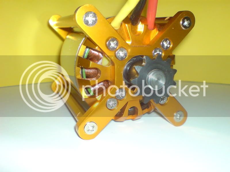
What are the dimensions I need to mark for drilling motor holes for the motor of choice: 63-74?
Hole size?


$300ish is a little high for me for the eboost. Aside from this, i don't need to mount batteries there, and I don't want to use lipos. Furthermore, I don't think it would fit properly with my geomtery (won't fit inbetween stays). I think eboost is mainly for touring and mountain geometry bikes. Lastly, I don't like the way it looks.
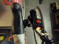
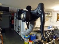
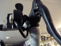
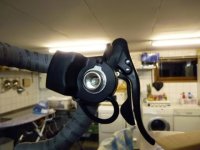
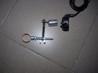
 
I saw that post when I went through the thread. I just was seeing if maybe others might come to encourage me to use what I already have. So you think it might have to be metal? I guess it would need to ahve the least give possible.
 
adrian_sm said:
So if others are interested I'll debug this thing properly, and get quotes for a small batch of the custom parts. Any takers?
I'm an enthusiastic supporter of FD. If your testing proves out, then I think you could do small batches of these to sell in the For Sale area on ES. If these can be produced cheap enough & your parts will last longer than the motor & battery, then I think you should be able to sell many at least as a kit for DIY. :mrgreen:

Anyway, I hope you continue with the R&D just so we can continue to refine the FD, and I hope you can find success with it as a DIY kit too... if that is your goal. I'm interested if your kit can work on a bike I already have, and you have good results with further testing. :wink:

Please shoot some video with the friction drive on the road. It would be ideal to watch the motor engage & disengage over a wide speed range, and nothing compares to an action video showing what it can do up close. You will generate interest & sales with a good video, imo. :idea:

:twisted:
 
Hillzofvalp,

Looks like things will change a bit compared to my design. It might be time to start your own thread.

But if you only have two weeks, I would just do a straight copy, otherwise you'll have lots of debugging/problem solving/time wasting. Remember this is still a WIP. :) I still don't have a throttle design I am happy with that suits road handle bars.

If you do your own design. Try and keep it a strong as possible. That bike lock mount won't be up to the task.

As for arm length the centre to centre distance I used was 50mm.

DeVries,

I might consider a small batch of kits, but just to help prove the design. Then I would look at a full plug and play design if it went well. The ES community appreciates the kit approach, but everyone else just wants something that works out if the box.

Good idea about the video too, it would probably help me understand it too.

When I am back home, I'll get stuck back into it.

- Adrian
 
hillzofvalp said:
Adrian, do you mind cutting me a mount as well as an arm (paid, of course. I don't know what you paid for materials though, but would estimate around $50 for whole deal shipped?)? I'm under the impression that you are not planning on going commercial with this. Correct me if I'm wrong.

Come on Adrian, that sounds like a very reasonable offer for half a days work :roll:
 
My initial impression was that Adrian had one lying around after deciding not to use two arms. I'm going to try to build one with the 1/8" aluminum I've got and some jb weld or something to keeep them together. It'll be around 12.7mm wide with four plates. Might consider 3. As far as the mount goes, i don't know which one to choose. One of the ones you guys linked me to might work out.

I'm drilling the holes on my plates now, and I plan on using one as the template for the others that are clamped to it. 9/32" is the right hole size? I'm left with 4-5" to work with for arm length.

Can someone link me to the part that explains how the tensioner is positioned/fastened? Any recommendation on which springs to use?

Thanks!

edit:
Hobbyking is out of stock of the KF 100 A. What would be my second choice when running the 64-73 outrunner? the castle 160A? It's a bit expensive....
 
I have links to some cheap clamps early on the thread that may work. I bought them from wiggle, but ended up I intergrating the clamp with the pivot.

As for the spring, it is not optised at all. I just found a fairly heavy gauge wire extension spring with a big enough internal diameter to fit over the main pivot shaft. Then trimmed and bent the ends. on end is fixed to the pivot block, the other end is fixed to the pivot shaft with that little aluminum ring. I just drilled an off axis but axial hole for the other end of the spring. To adjust it you just rotate the ring to take the weight of the motor, the do up the grub screw. Easy.

As for a ESC, I have used the smaller 85amp one from hobbyking, but only on the smaller motor. If you don't try and use the drive at low speeds it should be all right. I never had it get hot, I actually fried my little motor without it breaking a sweat.

Hope that helps.

- Adrian
 
9/32" is the right hole size?

If you are talking about the 4 holes in the motors stator plate where the shaft comes out, I have been using 5/32” drill bit(0.156”-3.96mm). I believe the print says it takes an M4 bolt and the factory hole is 4.2mm.
 
I meant holes on the arms for mounting the motor. I believe 5/32" is right (error in post) but I don't have a motor on hand to try.

Adrian: so you think the big 63-74 (the one you're working with) will be okay on a little 85A esc? Are we talking about using no motor under 15 kph?
I'm also interested in the Hyperion Z4045 solely because I don't want to deal with hobby king right now. They just sent me a $130 helicopter kit instead of my $30 charger. Are any extra parts required for the Hyperion Z4045 (I can get it for $84)?

Is it straight forward using the servo tester to control the esc?
 
I haven't tried the combination of 63-74 and 85amp ESC but if anything kills it it would be low speeds and lots of throttle.

Kepler has tried the Hyperion motors, search his threads for more info. Not sure what the bolt pattern spacing is.

As for the servo tester, if you are happy to use it directly to controller the motor it works perfectly, but I found it annoying. As I said before no one has a good solution to mounting a throttle on road bars.... yet.
 
Hello,i am new here . I have a good solution to mount the throtle on a road bike bar .http://eshop.meijerijzerwaren.nl/index.php?item=flamco-beugel-8-x-28-mm&action=article&group_id=10000065&aid=4726&lang=NL
 

Attachments

  • P1020076.JPG
    P1020076.JPG
    28.1 KB · Views: 4,459
  • P1020077.JPG
    P1020077.JPG
    27.5 KB · Views: 4,459
  • P1020079.JPG
    P1020079.JPG
    21.1 KB · Views: 4,552
  • P1020080.JPG
    P1020080.JPG
    24.3 KB · Views: 4,552
Ooooooo. Very interesting. Welcome to the forum, and thanks for posting.

So let me see if I have it right. You put one of these clamps around the handlebar tubes, have a little bracket rise up to a turned part that a standard thumb throttle can mount on. Then route than cable where you want, wrap you grip tape again and you are good to go.

Not a bad idea for a permanent throttle mount. I might just use that.

Is this your bike? How do you find the ergonomics if it. I find the thumb throttle a but tiring for long rides. But this was with it is a different non-standard location. Would love to hear how you find this location.

Thanks again for dropping by and sharing your knowledge

Cheers,

Adrian
 
hillzofvalp said:
I meant holes on the arms for mounting the motor. I believe 5/32" is right (error in post) but I don't have a motor on hand to try.

Adrian: so you think the big 63-74 (the one you're working with) will be okay on a little 85A esc? Are we talking about using no motor under 15 kph?
I'm also interested in the Hyperion Z4045 solely because I don't want to deal with hobby king right now. They just sent me a $130 helicopter kit instead of my $30 charger. Are any extra parts required for the Hyperion Z4045 (I can get it for $84)?

Is it straight forward using the servo tester to control the esc?

I have done plenty of testing with the 85A 63-74 combo. Works quite well but does get quite hot under constant load. I have had them tripping out on high temperature quite a few times but never actually hurt one. The 100A gives you a bit more head room.

The Z4045 is a nice motor. Bolt pattern is 25mm centre to centre. As this is 48mm motor, go with the 320 kv since speed is what you are after. Main negative with the Hyperion is that the bearings are quite small. I ended up retiring mine due to noisy bearings and not being able to find replacement bearings for it.
 
ES Post - throttle

Okay I need to start getting the electronics sorted out for this drive. My options are either the mythical Kepler interface, or a custom one. Let's talk about the custom one. 

So I was thinking of starting off with the Turnigy Watt Meter, making the shunt remote (thanks Jeremy), then modifying the software to do a few extra things (thanks Jonas). Here is my wish list:
- throttle interface to go from hall or buttons to the RC ESC input
- current limit, reduce PWM when limit is exceeded
- speed/distance display, will require a wheel speed sensor input
- minimum speed for friction drive, throttle set to zero below threshold speed
- 5v output for MagicShine style headlight/taillights from ESC BEC
- display mounted in custom waterproof enclosure on handlebars
- shunt mounted back at motor/ESC
- switch to turn it off/reset Ah/Wh/distance
- button to switch between display modes
- on/off switch for lights

Display modes I am thinking of having are:
1) Speed, distance, Wh/km, Wh used
2) Speed, distance, Ah/km, Ah used
3) Speed, distance, power, Wh/km instantaneous 
4) Speed, distance, Volts, Amps

So to do this I need some extra inputs:
1) mode button
2) wheel sensor
3) throttle input

And the throttle output. 

Now I need to see if this is all possible with the number of extra IOs available, and the programming options, space, speed we have available. 

- Adrian
 
Hi,thanks for the reply .Hope i can help for this throtle problem.I use it now 10 weeks on my roadbike with hub wheel 700c23.This system works perfect you can choose te right position with the parts on the photo.No problem to switch the gear.First photos campa,and i use shimano by my self.Ergonomics ,it is verry fine to use when you have found the perfect position.Photo with all the parts :D
 

Attachments

  • P1020387.JPG
    P1020387.JPG
    24.7 KB · Views: 5,320
Very nice work.

That final photo makes it crystal clear how to build your own. Thanks a lot for sharing.

- Adrian
 
Adrian I think you can have this but may change Up to ATtiny461 or 861 to get some free code space.
http://www.atmel.com/dyn/resources/prod_documents/doc8273.pdf
For button you can use a A/D input and get ex 16 input , Speed you have one free I/O for that.
Then you need to make some more change in program but that I think it will work.
//Jonas

Quote Adrian
So to do this I need some extra inputs:
1) mode button
2) wheel sensor
3) throttle input

And the throttle output.

Now I need to see if this is all possible with the number of extra IOs available, and the programming options, space, speed we have available.
 
I was really hoping to not have to make significant mods to the PCB like swapping for a bigger attiny. Being a Mech Eng my skills and patience with a soldering iron are limited, and little surface mount chip soldering is definitely outside my skill set.

Think I would prefer to limit what I try to get it to do instead.

Only just started looking at the assembler files now, and it us making my head hurt. I'll need a lot of help if I am going to make these changes. Any recommendations from people on where to start getting my head around the changes I would like to make. I haven't done programming in about a decade.

- Adrian
 
To answer my own post. I found this resource for programming these.
http://www.attiny.com/assembly.htm

- Adrian
 
What for the spring? Haven't seen too many springs made from copper, the yeild strength would be too low at a guess. Justplug the figures in to an online spring calculator and work it out for yourself.

Personally I would just find a real spring and modify.

- Adrian
 
Back
Top