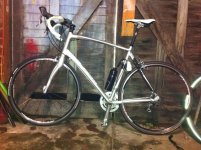
Commuter Booster - <1kg Friction Drive

Very Nice & clean Adrian... Good job !! Your doing good for others on the forum also ...

It looks like you , and I are on opposite ends of the bicycle spectrum .. You up on your Road bike ,and me down on my recumbent :lol: Best part is they are running .. Bill
 
How does it run?! it looks great. Do you think that the 63-74 will work on my 59cm steel frame? it looks like it would. I just ran into a speed bump because the mounts in my seat tube keep the batteries from going down. :(
 
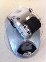
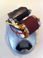
Update: Weigh-in, and size comparison
- CBv2 with 5063 motor = 0.65kg
- Full bike = 12.1kg !


Okay I upgraded the old CBv1 that had the small 5063 motor, to the CBv2 design. This includes:
- single swing arm
- adjustable dead stops
- new adjustable torsion spring

This shaved some weight off.
CBv2 with 5063 motor weighs: 646 grams, or 1.4 pounds
CBv2 with 6374 motor weighs: 1239 grams, or 2.7 pounds

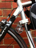
2011_01_09 - CBv2 - 5063 weigh-in (small).jpg
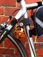
2011_01_09 - CBv2 - 6374 weigh-in (small).jpg

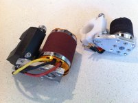
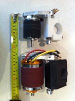
I also took a few photos to show the difference in size.
Here they are side by side on the bench. Bit hard to tell the difference.

2011_01_09 - CBv2 - 6473 vs 5063(small).jpg
2011_01_09 - CBv2 - size comparison (small).jpg

Once you mount them on the bike it is a lot more obvious. The larger frame motor only just fits my large framed bike. As I think this style of drive suits a road bike the most, I think I am going to focus my efforts on the smaller motor for now.

2011_01_09 - CBv2 - 5063 (small).jpg
2011_01_09 - CBv2 - 6374 (small).jpg

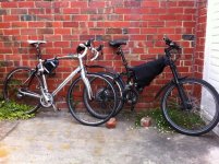
I still think the most impressive thing is the overall weight of the bike, only 12.1 kg :shock: , or ~27 pounds, with CBv2 5063, and 5s10Ah of battery, and CycleAnalyst on the bars. It makes my Giant AC1 with x408, and 80v10Ah feel like a motorbike, at 32.1kg, or ~71 pounds.

2011_01_09 - Avanti Giro - CBv2 vs Giant AC1 - 408 (small).jpg

Now I just wish the weather forecast would improve, so I can get some more road time on it. As I have not weather proofed anything yet, I am reluctant to use it on my commute to work yet. Maybe this is just mother nature's way of telling me I need to resolve that issue now. :)

- Adrian
 
adrian_sm said:
Update: Weigh-in, and size comparison
- CBv2 with 5063 motor = 0.65kg
- Full bike = 12.1kg !

Okay I upgraded the old CBv1 that had the small 5063 motor, to the CBv2 design.
Most excellent documentation, as usual. 8)

Can you make a video that shows how you adjust the motor into the ideal location/position, or explain that adjustment in detail?

Can you shoot some video of the friction drive working on the road showing it engaging & disengaging the tire?

Please, please, please. :p

Thanks! :D
 
Sure. I just need to finish the camera mount for the on-road shots.

As for drive adjustment, I still don't know the optimum yet. So will hold off sharing the installation instructions until I do.

- Adrian
 
Update: Weatherproofing & ESC mounting

Playing around with ESC mounting, and weather proofing at the moment. I was planning on using a little electronics enclosure and cutting a hole for the ESC heat sink to poke out. Then mount the enclosure to the bike somewhere. This would protect the ESC from the elements, let me hide any additional electronics and provide panel mount connection possibilities for throttle, lights, dashboard. But I might just make the enclosure the ESC came in waterproof instead, and keep wiring exposed. The 85A ESC comes with a 5 sided plastic cover, that wouldn't be too hard to seal up, leaving the heatsink exposed. Unfortunately the 100A ESC only has a 3-sided plastic cover, so this would be a bit more of a challenge.

As for mounting positions, I tried a lot of different spots, but only liked two of them, and one of those would restrict the frame size the drive would suit. So then there was one.
- ESC to be screwed on to the front/centre of the clamp/pivot block in the vertical orientation.
- ESC battery wires enter from the bottom, phase wires exit out the top.
- motor phase wires now enters the bottom of the motor to add a drip loop.

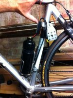
IMG_1782.JPG
Here is the bike in minimalist mode, <12kg.
- CBv2 5063
- 85A ESC
- Single 5s 5000mAh battery in the water bottle.
IMG_1784.JPG
- Adrian
 
It will have to wait until the weekend. I am back at work now, and the weather is pretty dodgy. But the weekend looks good.

How is you build going?

- Adrian
 
Just realised something pretty good. Bikes have standardised seat tube outer diameters, for deraileur mounts etc, and variable inner diameters to shave weight, or increase strength. This means there are heaps of difference in seat post diameters, but only a few seat tube outer diameters.

- Older style road bikes 28.6mm (1 1/8")
- Newer style road bikes 31.8mm (1 1/2") <-- Size of my white CB
- Mountain bikes 34.9mm (1 3/8") <-------- Size of my black CB

Too easy. :D No need to stuff around with shims if someone wants to try out my drive on their bike. 8)

- Adrian

[EDIT] Old steel frames, really cheap bikes and BMX's may have a 25.4mm (1"). But I think the 32.8 & 34.9mm sizes cover most modern bikes this drive would suit.
 
Adrian,
your drive is a very attractive option , but its main limitation is (as you mentioned earlier) that most modern bikes are designed with a "compact" frame layout to minimise weight and maximise rigidity etc. That means that there is a smaller rear triangle . Only the biggest frames on road bikes have space where you fit your drive.
Checking my current collection of 6 bikes ( 2 MTB, 2 Road, 1 commuter, and one BMX) ..only one of the MTB's has space to fit even a 50mm motor in the triangle ( even then there are issues with shifter cables on the seat downtube !)
In contrast , i believe all of them could be fitted with a "Kepler" style drive.
so, not a knock at your brilliant compact design, but i suspect potential users will have to either be lucky with their current bike, or deliberately select a bike with sufficient space in order to fit your drive .
 
You are absolutely right. The two biggest mounting problems are:
1) Motor Size
As Kepler just mentioned in another thread, the 50mm motors just don't have the thermal mass of the 63mm motors. So they are inherently less robust.

2) Frame Space
A lot of modern road frames just don't have the space.

Add these two competing issues together and it will definitely restrict who can use the drive on their bike. Actually I might make a 2D template that can be printed to make it easy to see if it will fit a frame. Hmmm.

And finally the shifter cable problem. I hadn't mentioned that before in this thread, but some bikes do have the shifter cbales running down the back of the seat tube, rather than up from the bottom bracket. These cables are exactly where I clamp my drive. There are ways around it. But I need to have a look at a few more frames before I decide which solution I would chase.

- Adrian
 
Good stuff! I love it when we get more improvements to design by sharing here!

I have to ask, though, what with the limited space in the placement of the CB, isn't it going to mean you have to choose to have more motor slip due to the angle at which the drive engages? If you tried to draw a straight line from the pivot, motor and rear hub, wouldn't the motor still be considerably under that line (meaning forward towards the front of the bike)?
 
Not sure. I think it was Kepler that said this is the optimum engagement, to be able to draw the straight line between motor pivot, contact patch, and wheel hub. I don't quite agree and have been setting up my drives to limit the travel before that point with success.

I think I outlined my reasoning in this earlier post. But I have not totally convinced myself so take it with a grain of salt.

I can still have the same amount of engagement with the tyre but at an angle. The allowable angle is dictated by the coefficient of friction between motor and tyre. Come to think of it this will be the worst when the motor is first coming in contact with the tyre when you will have the largest angle. This could be improved by increasing the radius at whcih the motor pivots. :shock:

Damn. That is a good argument for a longer pivot arm.

:D Funnily enough now that I have a single pivot arm, I could fairly easily do this by placing my pivot point infront of the seat tube, and having a longer pivot arm. Hmmm. It would increase weight, but may help avoid slip during initial pick up. But it would also require the drive to pivot further to have the same engagement into the tyre. So it wouldn't help trying to get it on smaller framed bikes. Damn.

From my understanding of the geometry, the most critical time it will slip is during initial engagement for the pivoting designs like mine and Keplers. Once it gets over that point the geometry will only be able to apply more contact force until it is limitted by a force balance, or deadstop. If you slip at the fully engaged position you would need to adjust the drive such that you acheive more engagement, ie. lower the drive, or adjust the deadstop.

To directly answer your question. Yes the geometry of the frame does limit the travel of the CB, and could restrict engagement. But you don't need to aim to have a fully straight line between motor pivot, contact point, and rear wheel hub. You can stop short of this and have just as much tyre engagement.

- Adrian

P.S. One of the other reasons I don't let the drive pivot that far, is that you see a drop off in the torque required to maintain the drive in that position as you get closer to the straight line. This means the drive suddenly accelerates its rotation towards the deadstop, and hit is with a bit of a clunk. I was previously just adding a dampening material to my deadstop, but by adjusting the geometry I effectively used the compliance of the tyre to do the job instead.
 
Update: Installation Tempalte

For those interested if this style of drive is even close to fitting your frame, I made a very rough template you can cut out and try.

I used the "Kepler" approach of engagement (every thing in a straight line), as this appears to require more travel then my approach, so the templates should be pessimistic.

Anyway if you do try it, please let me know if it worked or not. I am beginning to suspect a lot of frame will have issues with space or cables, and that I have just been lucky with mine.

- Adrian
 

Attachments

  • Commuter Booster v2 - The “Will it fit my frame” Template - rev A.pdf
    691.1 KB · Views: 531
I have been working on the battery packs more recently, but I did get four ~7/4x1/8x4"arms made which have terribly drilled holes. Even when I used the whole punch it went off a little.

The club I'm participating in is new at Purdue University, and you can check it out at electricvehicleclub.org, which was only put up couple of months ago. Many of the senior members are affliated with Purdue's evGP electric go-cart racing, so I suspect my future prototypes will come together well after having gaining access to machinery and guidance in the engineering building.

Actually, the brand new machinery rooms at purdue are very sophisticated, and they even have job openings. I plan on applying soon so I can learn to use their cnc and maybe even their water jet machines someday. Pretty cool oppurtunity, and, if I major in Mechanical Engineering, it will look really good on resume ;).

LUCKILY, my frame is pretty big at 59cm, not to mention they're 1" 1/8" tubes, also giving me extra room. I will try out the template today and get back to you, but I still haven't ordered a motor or esc yet. Waiting to see what club thinks. Btw, could/did you experiment with different tire widths?
 
hillzofvalp said:
I did get four ~7/4x1/8x4"arms made which have terribly drilled holes. Even when I used the whole punch it went off a little.
Did you use a drill press, or hand drill? The motor mounts holes can be off a little, but you defintely want the pivot axle hole a very close fit for the pivot shaft, if you want to go for a single arm design.

The club I'm participating in is new at Purdue University, and you can check it out at electricvehicleclub.org, which was only put up couple of months ago. Many of the senior members are affliated with Purdue's evGP electric go-cart racing, so I suspect my future prototypes will come together well after having gaining access to machinery and guidance in the engineering building.

Actually, the brand new machinery rooms at purdue are very sophisticated, and they even have job openings. I plan on applying soon so I can learn to use their cnc and maybe even their water jet machines someday. Pretty cool oppurtunity, and, if I major in Mechanical Engineering, it will look really good on resume ;).

Defintely get as much hands on experience at Purdue as you can. It will pay off. And you can get your own jobs done :D
Before you decide on your major, think long and hard about the type of job you would ultimately like. For what I am doing now, a mechatronics degree would have been better suited, than the Mech Eng/Bach Commerce I did.

LUCKILY, my frame is pretty big at 59cm, not to mention they're 1" 1/8" tubes, also giving me extra room. I will try out the template today and get back to you, but I still haven't ordered a motor or esc yet. Waiting to see what club thinks. Btw, could/did you experiment with different tire widths?

As for the motor, the 6374 seems like a good cheap option. If you go smaller you will be restricting the power that it can reliably handle. So I would recommend the large 63mm motor, in as lwoer a kv as you can get, with the best bearings, and preferably a skirt bearing to internally support the motor can.

Tires. No other that switching between my mountain bike, and road bike. Both have worked. Thye both have a pretty smooth centre section for contact. I don't think I am getting close to enough torque to shear the rubber so a narrow road tyre doesn't appear to limit things too much.

- Adrian
 
Ugh, I hate dealing with hobbyking. I wish I could get a cheap 63-74 in the US.

My question about tires is more along the lines of: Will a 28mm, wider tire, work better? Maybe ideal tires or tire pressures could be investigated. how much surface area contact is ideal?

I've got 20mm on my bike now (hehe a little small) but I've got some 23s as well.
 
I have 23s on my bike. Worked fine.

As for ideal. I haven't spent much thought on it. I would prefer it to work on whatever is one the bike already.

One thing to note is that a wider tire is usually taller, which will restrict space for the drive.

- Adrian
 
hillzofvalp said:
My question about tires is more along the lines of: Will a 28mm, wider tire, work better? Maybe ideal tires or tire pressures could be investigated. how much surface area contact is ideal? .

I think that is referred to as... "sweating on the details" ... whilst ignoring the real issues. ! :lol:

build the drive onto a bike first ..then refine the details like tire size etc once you have a working test bed.
Unless you plan on a multi kW drive, friction onto the tire wont be one of your biggest problems.
 
adrian_sm said:
Not sure. I think it was Kepler that said this is the optimum engagement, to be able to draw the straight line between motor pivot, contact patch, and wheel hub. I don't quite agree and have been setting up my drives to limit the travel before that point with success.

I think I outlined my reasoning in this earlier post. But I have not totally convinced myself so take it with a grain of salt.

I can still have the same amount of engagement with the tyre but at an angle. The allowable angle is dictated by the coefficient of friction between motor and tyre. Come to think of it this will be the worst when the motor is first coming in contact with the tyre when you will have the largest angle. This could be improved by increasing the radius at whcih the motor pivots. :shock:

Damn. That is a good argument for a longer pivot arm.

:D Funnily enough now that I have a single pivot arm, I could fairly easily do this by placing my pivot point infront of the seat tube, and having a longer pivot arm. Hmmm. It would increase weight, but may help avoid slip during initial pick up. But it would also require the drive to pivot further to have the same engagement into the tyre. So it wouldn't help trying to get it on smaller framed bikes. Damn.

From my understanding of the geometry, the most critical time it will slip is during initial engagement for the pivoting designs like mine and Keplers. Once it gets over that point the geometry will only be able to apply more contact force until it is limitted by a force balance, or deadstop. If you slip at the fully engaged position you would need to adjust the drive such that you acheive more engagement, ie. lower the drive, or adjust the deadstop.

To directly answer your question. Yes the geometry of the frame does limit the travel of the CB, and could restrict engagement. But you don't need to aim to have a fully straight line between motor pivot, contact point, and rear wheel hub. You can stop short of this and have just as much tyre engagement.

- Adrian

P.S. One of the other reasons I don't let the drive pivot that far, is that you see a drop off in the torque required to maintain the drive in that position as you get closer to the straight line. This means the drive suddenly accelerates its rotation towards the deadstop, and hit is with a bit of a clunk. I was previously just adding a dampening material to my deadstop, but by adjusting the geometry I effectively used the compliance of the tyre to do the job instead.

One of the good things about this type of design is that the geometry is quite flexible. I think the "straight line" geometry is still the optimum setup, at least for my drive but I can also see that with a shorter swing arm, you can stop short of this and still have good pick up at first start.

Having the pivot on the opposite side will certainly open up some bike frame options. Be careful not to step on some "hidden" patents though :)
 
Motors: the 63mm Turnigy with a skirt bearing and a 200-kV is proving to be popular, but keep in mind that before rushing into that one, Kepler is testing the similar 63mm Aeolian motor with a 170-kV, results to be posted soon.
 
kevo said:
Adrian,
Love your bike build and writeup! Do you have a link for the triangular bag on your white road bike?

Thanks. It was from Aldi. I think it is one of those items they only occasionaly stock. At least in Oz.

Kepler said:
Having the pivot on the opposite side will certainly open up some bike frame options.
Probably only in avoiding shifter cables.

Kepler said:
Be careful not to step on some "hidden" patents though :)

:)
 
I think I am more worried about infringing on John's (Kepler's) design.

There are heaps of differences between mine and the other "hidden" design
Theirs has a one way bearing, mine mechanically disengages
Theirs has an in-runner motor mounted infront of the tube, mine an out-runner behind
Theirs has belt drive with reduction, mine direct contact.
Mine uses rotational inertia reaction to engage the tyre, theirs remains in contact via spring.
.
.
.

The main common ground is the pivot mounted to the seat-tube, but I can't see that being an individual claim in the patent.

I think I am clear.
 
Back
Top