Adding hall sensors to outrunners

Jeremy Harris said:
Thanks for that, Ryan, looks like I just got lucky with all the other motors I'd modded this way and unlucky with the 6374 I did at the weekend.

Jeremy


Yep, just unlucky. Since you can actually advance the electrical signal quite a bit and the motor will still work at low speed and work better at high speed, you really can put the hall sensors almost anywhere (as long as they are all 120deg electrically apart) and find a combination that gets the motor working.
 
I am looking to modify a large "scorpion" outrunner for hall effect sensor operation. Couple of issues with this: 1) the motor has 18 stator poles and (I think) 20 magnets; and 2) being an "upmarket" type of motor, it seems to have a much better magnetic circuit in the bell. The upshot of this is that very little flux leakage occurs - ferrous items simply don't stick to the outside. Compared to the big turnigy that catches any nut or screw I drop...
The problem is that I've managed to convince myself that external hall sensors are the way to go; better than internal in that
1)easy timing adjustment
2)no grinding of stator
3)no routeing issues with sensor wires
4) less work (I need a lot for my project)
and sensorless operation seems to be unreliable below 10% speed
I'll make up a jig with 3 sensors at 60degrees mechanical on the outside & see what the signals look like; but I do fear the signals will be noisy. (60degrees signals is a single signal inversion away feom being 120degrees signals, but far more attractive mechanically! Or I could just fit the middle sensor upside down??) Originally I thought the halls could be right next to each other - getting the 120degree phasing from a single magnet... but this thread has shown the error of that assumption!
By the way - the project will have quite a lot of motors in fairly close proximity, which will also screw about with external fields... (90mm centres, 65mm rotor diameters)
 
bobc said:
I'll make up a jig with 3 sensors at 60degrees mechanical on the outside & see what the signals look like; but I do fear the signals will be noisy. (60degrees signals is a single signal inversion away feom being 120degrees signals, but far more attractive mechanically! Or I could just fit the middle sensor upside down??) Originally I thought the halls could be right next to each other - getting the 120degree phasing from a single magnet... but this thread has shown the error of that assumption!
You can glue the same number of magnets to the outside of the can as there are inside and use those for position sensor, you can use any sort of little magnet as long as each side only has one pole. I am pretty sure someone already mentioned that in this thread, I am just to lazy to try and find it. I think the flexible magnets (like you would put on a fridge) have south and north poles on the same side, so they won't work. Use a compass to make sure you alternate positions. To figure out the mechanical spacing between sensors, use the following logic/math.

each pole pair is 360electrical degrees
If you have 20 magnet poles in the rotor, that gives you 360degrees electrical is 18degrees mechanical. or 1degree electrical is 0.05degrees mechanical.

That means that 120degrees electrical is 6degrees mechanical. So as long as you put your sensors multiple of 6degrees apart from each other, you will get some form of 120 degree commutation, There is a little bit more to it to make sure that they are all in the proper phase, but if you keep them all equally spaced, it should work. The 60deree separation that you proposed should work fine, but something that comes out of the above calculation is the precision that you have to have on your sensor placement. If you are out by 2 mechanical degrees, you have just moved your timing out by 40electrical degrees, so when you built your sensor mount, you need to ensure that the sensors are accurately placed relative to each other.

-ryan
 
There was some time ago a plastic film with magnetic particals in it, in a window on a paper card, placed on a magnet you could see the shapes of the magnet flux.
 
JEB said:
There was some time ago a plastic film with magnetic particals in it, in a window on a paper card, placed on a magnet you could see the shapes of the magnet flux.

Yep, something like this

http://www.teachersource.com/ElectricityAndMagnetism/EddyCurrentsAndMagneticFields/MagneticFieldViewerCard.aspx

Or it looks like you can make your own.

http://www.instructables.com/id/3D-Magnetic-Field-Viewer/
 
Ludo91 said:
Hi, exactly what hall sensor have you used? may you tell me its specific code so I can look it up on DigyKey?
thankyou so much :D

I've used Honeywell SS411A sensors and found them to work very well.

Jeremy
 
Ludo91 said:
extremely fast reply! thnakyou so much dude :)

edit: have you tried those sensor both glued between stator poles and outside the motor`s can?

Yes, they work fine either internally or externally, no problem.

Jeremy
 
Yesterday I got my two channel scope and checked the hallsignals of my first sensored colossus.
At first I was dissapointed, because the scope didn't show anything on the halls output, but then I remembered Jeremy mentioned pullup resistors :roll:
FYI; I glued the sensors upside down in the slot between two twin tooth. ( should be OK for Delta ) I thought it was easier this way, because the 45°edges of the sensorfront snugs neatly in the slot.
But I couldn't find a matching phase. Either the halls were advanced, retarded or 180° shifted. Maybe that's another reason why the motor is so noisy ?

On my second motor, I glued the halls face up between two phases and wired it in wye. What a difference! Not only the hallsignals matched the phases. The motor only has a 0.1A no load current at 46V, spinning with 800rpm. And it's quite powerful. If it wasn't built for an airco-compressor drive, I would use it with a single reduction on my recumbent!

t80-85_100t_w_halls.jpg

-Olaf
 
That's interesting, Olaf. I've always fitted the sensors with the flat face outward when fitting them in the slots.

My experience of the motor no-load current and torque at low rpm is like yours, a massive improvement from running the same motor on a sensorless controller. I've also found that wye connected motors run much more smoothly at low speed and draw a much lower no load current. My plan at the moment is to wind my Colossus as a fairly high Kv (around 150 to 200) wye connected motor because wye seems to work so smoothly compared to delta at low speeds.

Jeremy
 
I agree Jeremy, wye is the way to go.
Also for our poor controllers and batteries. Up the voltage and drop the current to get the same result.

I just finished the third motor and will fit the sensors 'face down' but between the phases for a wye-wound motor.
Then I'll repeat the hall-matching procedure again and see how it works best.
I'll use meltglue and kapton tape this time to fix the halls. Easier to disassemble, if things go wrong. ( No power tests possible though...
-Olaf
 
Whats wrong with these motors?
I merely changed the winding on the third one to get 40kV in wye and I got more than 8A noload current with an RC-esc and 46V? The motor is hard to turn by hand. It's not a short between stator&windings. Must be a short between stator and shaftholder?!
I have finished two colossus' and one turnigy 80-85 and the turnigy is the only one, who turns easy by hand. I was hoping, it's related to better magnets in the colossus, but that wouldn't make the motor cook after some short noload runs.
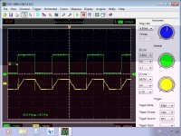
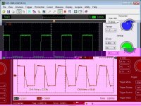
Here is a snapshot of a hallsensor and one phase. Can anyone tell from the yellow curve, whats wrong with this motor?

55wx4wye_phaseA.jpg

Maybe the rc-esc had trouble with finding the right timing and with a sensored infineon it would run better. I'm afraid to test it, since I had three 'lab-accidents' last week...
-Olaf
 
I think it looks a bit like a shorted turn somewhere, Olaf. This would explain the high no load current and the increased cogging when turning the motor by hand. My guess is that two wires have somehow got damaged during winding and are shorting - it will probably be quite difficult to find without stripping the motor, unfortunately.

Jedremy
 
Olaf,
I had the same symptoms when re-winding AJ's motor origanly. I could not find any short from the windings to the stator...but careful measurment did show a minute varyance in coil resistance. After all was said & done I am 99% certain that I had coils shorted to each other or to a single lamination in the stator that I couldn't find with the meter. The cogging felt very different than when conecting phase wires together like in a generator application.

Re-insulating the stators solved my problems on the 2 occasions this has happend to me. I wraped the damaged stators with dyneema thread (hi performance fishing line) to better protect the windings. yes its a ton more work...sorry to say.
Good luck. T
 
Rewinding is no issue, the wires aren't epoxied yet. But before I do that, I check the last unwound stator for lamination shorts with each other or with the shaftholder. If that's the cause for the trouble, Markobetti will get a package from me...

I gathered all my guts and tested the turnigy with the all new 150v 12FET infineon I got from Lyen. And it runs smooth as butter at 120V :D
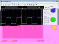
The scope picture didn't look much different to the previous one: The spikes are not the problem though.
t80-85_100t_w120V.jpgView attachment t80-85_120V.jpg

Have a nice sunday
Olaf
 
I don't think that inter-lamination shorts or a short from the laminations to the bearing carrier would have this big effect, although a winding to lamination short might. My money is still on a shorted, or partially shorted turn somewhere, or maybe a turn shorted to one of the laminations.

Jeremy
 
When I mount the bell on an empty stator, would it run free if the stator has shorts with the shaftholder?

It's ironic, I had to remove the original wire from the turnigy and hadn't been extra careful using a lathe to cut off the copperhead and a hammer to punch out the epoxied wires.
Turns out, this is the only motor running well so far. :lol:
BTW: It runs without skirt bearing so far. That's where the 0.1A noload current comes from.
-Olaf
 
olaf-lampe said:
When I mount the bell on an empty stator, would it run free if the stator has shorts with the shaftholder?

I think it should, as any eddy currents are going to be mainly flowing in the outer edges of the stator - I don't think that having the stator laminations contacting the shaftholder would cause a problem.

olaf-lampe said:
BTW: It runs without skirt bearing so far. That's where the 0.1A noload current comes from.

That doesn't surprise me, for the sort of use we're putting these motors to I don't think we really need the skirt bearing. Exceptions would be people making friction drives and maybe someone building a trials or dirt bike, where severe shock and vibration might present a problem, but most of the time we're not loading these motors with anything like the side and gyroscopic forces that an aerobatic model aircraft would impose.

Jeremy
 
Can someone put this very simpy:
Where and in which direction do I put the (3) hall sensors inside an Outrunner, on the stator?
I read through all this and are not much wiser.
 
There is a lot of explanation in this thread:

http://endless-sphere.com/forums/viewtopic.php?f=30&t=9061&p=325809&hilit=+4th+slot#p325809
 
OK I've read through this thread a few times (and even replied a while back) but it's getting so long that I found myself skim reading, missing parts and getting annoyed with myself so I'll just ask for a quick clarification to the following:

As previously stated I have an Axial flux motor that I am building. I want to mount hall sensors internally on the stator. It's a 9 tooth, 6 pole motor. This means the motor has 3 pole pairs. 360/3 is 120 degrees, with 3 hall sensors that means they need to be placed 40 physical degrees apart from each other around the stator.

The question is thus: is there a specific place they should be placed? Right in the middle of a tooth/coil? In the gap between teeth? Towards the outer rim of the stator or (as I suspect) as close to the center of the magnetic pole pairs axis as possible? I understand the position is calculated relative to the position of the stator - but how does the controller know where on the stator the sensors are located?

I'm going to go back and read some more I think...

EDIT: I have read through the thread Burtie linked to above, but as with this one I probably managed to miss the important bits. For the record I get the impression that sticking them between the teeth (the spaces between each adjacent coil) at around the distance from the center of the axis of rotation to half way up the coils is the way to go. 8)
 
You'll wind the stator ABCABC... which makes it neccessary to put the halls right in the middle of a tooth. If you put it between teeth, you'll need to know which direction the motor will spin. One direction you'll have a retarded hall signal; in the other it is advanced. The best way of course is to make it adjustable...
-Olaf
 
Back
Top