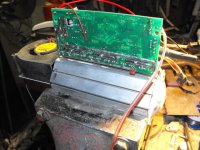
Doc EXTREME 36 FETS controller

Forget the case and the copper bar. Put the fet banks on separate heat sinks (add the isolated coolant tubes if you want) and add a few coats conformal coating to mechanically and thermally protect the board components and electrically insulate everything. Then just put it all in a plastic or wooden box with a couple of small centrifugal fans, and viola a controller you don't have to worry about changing FETs on again.

FWIW, forced ventilation of a stock alignment works extremely well, so you could just assemble it normally, conformal coat, and ventilate. It almost doubles the case surface area as a heat sink, and allows the surface area of all components to dissipate heat directly instead of baking inside a hot stagnant controller.
 
John in CR said:
Forget the case and the copper bar. Put the fet banks on separate heat sinks (add the isolated coolant tubes if you want) and add a few coats conformal coating to mechanically and thermally protect the board components and electrically insulate everything. Then just put it all in a plastic or wooden box with a couple of small centrifugal fans, and viola a controller you don't have to worry about changing FETs on again.

FWIW, forced ventilation of a stock alignment works extremely well, so you could just assemble it normally, conformal coat, and ventilate. It almost doubles the case surface area as a heat sink, and allows the surface area of all components to dissipate heat directly instead of baking inside a hot stagnant controller.


Without or with a small heatsink that works only with a few watts.
If you will have more power, then you will have also more loss in the FETs!
On the contrary, there is a large choice of industrial IGBT-Modules, but I don't tested it on
my BLDC controller. The price of the IGBT's are insane, but the 1200AMPs per module are
insane too!!!
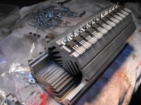
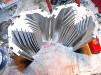
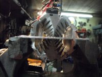
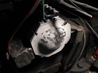
I'd to prever a tunnel heatsink, here I can fix a blower fan like I want.
If DOC take 2 of this 0.4K/W heatsinks with a "papst" fan, he can blow 500 watts in loss away!
So the high power controller could be very compact and light weight :wink: :wink: :wink:
This model of heatsink is made of 2 halves, very user friendly! :mrgreen:

http://www.elv.de/Leistungs-Luuml;fteraggregat-LK-75/x.aspx/cid_74/detail_10/detail2_2613/flv_1/bereich_/marke_
 

Attachments

  • Kühlkörper.Versuche.JPG
    Kühlkörper.Versuche.JPG
    61 KB · Views: 2,006
  • Kuehlkoerper.modifiziert.JPG
    Kuehlkoerper.modifiziert.JPG
    64.2 KB · Views: 2,006
  • Controller.mit.Kuehlkoerper1.JPG
    Controller.mit.Kuehlkoerper1.JPG
    45.3 KB · Views: 2,006
  • Kuehlkoerper.Umlenkung.JPG
    Kuehlkoerper.Umlenkung.JPG
    34.9 KB · Views: 1,995
  • Controller.mit.Kuehlkoerper2.JPG
    Controller.mit.Kuehlkoerper2.JPG
    71.6 KB · Views: 2,006
Lowracer, as usual all I can say is WOW, and yes of course that is the right way to do it.

My point was really about ventilating everything. With some simple ventilation Doc's 18fet controller from '09 would probably still be alive operating under the same conditions it failed.
 
John in CR said:
Lowracer, as usual all I can say is WOW, and yes of course that is the right way to do it.

My point was really about ventilating everything. With some simple ventilation Doc's 18fet controller from '09 would probably still be alive operating under the same conditions it failed.

Yes.. guys... ventilation.. BUT... That create a problem... ebiking during RAIN !!!... airflow mean exposed electronic part to the rain and moisture!

most of the very powerfull controller on the industry.. including E-cars dont work with fan.. they use sealed enclosed electronic and sometime watercooling.

My goal is having a controller that is compact and can still have multi kW continuous.

and... during next winter i could use the hot water to warm my jacket when ebiking in cold conditions too...

The bike frame offer also alot of great aluminum surface to fix copper tubing to transfer heat..

Lowracer, I already have couples of great monster heatsink similar to the one you showed.. these remind me old Class A Hi Fi amplifier project i've made in the past :mrgreen: But they are too big.

Also. I really want trying watercooling for a first time. I think now you understand why i'm sticking with watercooling :lol:


Doc
 
Doctorbass said:
and... during next winter i could use the hot water to warm my jacket when ebiking in cold conditions too...

Wrong fluid for winter... circulate propylene/ethylene glycol...
 
texaspyro said:
Doctorbass said:
and... during next winter i could use the hot water to warm my jacket when ebiking in cold conditions too...

Wrong fluid for winter... circulate propylene/ethylene glycol...

Yes... As well! :D
 
Doctorbass said:
John in CR said:
Lowracer, as usual all I can say is WOW, and yes of course that is the right way to do it.

My point was really about ventilating everything. With some simple ventilation Doc's 18fet controller from '09 would probably still be alive operating under the same conditions it failed.

Yes.. guys... ventilation.. BUT... That create a problem... ebiking during RAIN !!!... airflow mean exposed electronic part to the rain and moisture!

most of the very powerfull controller on the industry.. including E-cars dont work with fan.. they use sealed enclosed electronic and sometime watercooling.

My goal is having a controller that is compact and can still have multi kW continuous.

and... during next winter i could use the hot water to warm my jacket when ebiking in cold conditions too...

The bike frame offer also alot of great aluminum surface to fix copper tubing to transfer heat..

Lowracer, I already have couples of great monster heatsink similar to the one you showed.. these remind me old Class A Hi Fi amplifier project i've made in the past :mrgreen: But they are too big.

Also. I really want trying watercooling for a first time. I think now you understand why i'm sticking with watercooling :lol:


Doc

Conformal coating. That's how electronics are protected under water and for other harsh environments. For extra insurance you can easily use a downward slanted intake tube(s) or duct that makes it virtually impossible for water to enter.
 
Doc, even with the water cooling setup i'm going for, I still plan on putting a blower in the case of each controller. There is no reason to have 0 airflow, even if your fets are kept perfectly happy there are other components that will have at least a bit of heat buildup (shunt, caps, traces if not properly done). I will keep my controllers well out of harms way on my motorcycle, so I won't worry too much about water being sucked into the case.
 
Tonight i decided to test the water cooling idea with the first iidea i planned with the copper tube inside the "L" Bar just back to the mosfets.

I installed 5 x 10W DALE resistors on the heat sink .. just where the mosfet would be installed.

I used a little airpump to pump water and two temperature probe to measure the water temperature and the heatsink.

( btw.. I finally succeded to solder using brazing, the copper tube to the aluminum heatsink.)

The water measured waterflow was: 425ml per minutes
The ambiant temp of the water at input was 22.3 degree C
The water at the output of the heat sink tube was 24.9 degree C
The dissipated power was exactly 100Watts ( i doubled the power to the resistors)
The heat sink was at 34 degree Celsius

so that 100Watts of heat increased the heat sink temp by ( 34 - 22.3) =11.7 degree C

Conclusion: for each watts of heat, the temp increase is 0.117 celsius at a waterflow of 425ml/min

I took a little video of that:

(In that video i'm using 50 Watts for the test)
[youtube]XhZsYh86mKg[/youtube]

Doc
 
Doc did you use an insulator between the resistors flowand the aluminum bars? you should test the difference in heat at the bar with different water flow rates.
 
CamLight said:
Nicely done!
Where did you measure the heat sink temperature?

At 0:59 you can see where it is, I pointed it with my finger.

But probably i should install it closer to the resistors.. just like between two resistor near the output of the last resistor ( the one that is close to the liquid output and that is the most hot)

I was still very impressed to see how fast the heat sink get cold with so low liquid flow rate!

After i soldered the copepr tube using brazing solder, i noticed that the flatness of the aluminum has changed a bit so i reworked it a bit to get the flatness back.

To avoid too complicated fabrication i think i'll keep this method of liquid cooling i already prepared, but i will add the option of soldering the mosfet in group of 6 to a copper sheet under them.( just like you see on the video) That will help better current share, heat share and will ameliorate the effective surface of the mosfets to the aluminum bar by a around factor 2. But i will insulate them with the grey silicone insulator because i like the rubber effect that compensate for the flatness and also the little spring load effect it add to keep constant pressure. I know the thermal conductivity if it is not so good, but that's with it that i had the less problem with all my controller. Kapton was too hard and the pressure against the mosfet to the heat sink was not stable enough.

Doc
 
tostino said:
Doc did you use an insulator between the resistors flowand the aluminum bars? you should test the difference in heat at the bar with different water flow rates.

No i did just used thermal paste. The goal was not to test the thermal conductivity between the resistor and the aluminum.. but just to test the heat extraction of the liquid cooling.

Yes, that wold be nice to test at different waterflow rate.. that would give the answer to the slope of the liquid flow vs heat extracted and also give the offset generated by the air cooling contribution that affect also the the entire system in the equation.

Doc
 
Your test seems to be reasonably close to the math.

W (rejected heat)=((water temp in - water temp out) x water flow in L/s x specific heat of water)x1000

W=((24.9-22.3) x 0.00708 x 4.19) x 1000

=77 W of rejected heat through the water source.

Heat transfer inefficiencies would account for the difference due to a relatively high approach temperature between the heat transfer surfaces.
(34-24.9= 9.1K approach) Improving this approach temperature would improve how much heat is transfered to the water. As it stands, It looks like approximately 25% of your heat is being rejection directly to the air.

Doubling the water flow will effectively double the heat rejection capability (at that DeltaT)
 
The tube size looks a lil on the small size Doc, in comparison to what i am using in my PC watercooling setups where cpu temps at least comparable to the heat your putting into the alumnium bars with the moffsets, in fact your temps are likely to be even higher i'm guessing.... 7/16 tubing rammed onto 1/2inch ID fittings is the standard with PC watercooling. So, why such small ID tubing with this setup i am wondering? Also, was curious to what pump and heat exchanger your planing on using? I was looking at my 12fet Infineon on the weekend and thought how much work it would be to run a copper bar waterblock on the fets a mcp-350 Laing pump to move the water through a 120 or 240 size Thermaltake heat exchanger, would fit neatly on the my bike but... trying to keep with a more 'bicycle' look, hanging rads and pumps off it sooorta distracts from the whole bicyle thing a lil haha ... I'm prolly best sticking to watercooling my pcs for now :wink: haha... All the best for a leak free good performing cooling setup Doc :)

KiM
 
What is the final steady-sate temperature without water flowing and also with the output water being recycled into the input tank? That should give a good indication of the system performance. I assume you will be using a radiator/heat exchanger in the final design, but seeing how it behaves just recirculating a gallon or so of water should be very informative.
 
Kepler said:
Doubling the water flow will effectively double the heat rejection capability (at that DeltaT)

Yes, I plan on using alot more waterflow. This was just a little piston AIR pump that i used to pump the water.. so the performances was really poor.

Btw.. thanks for the math.. . I always remind about 50 to 100% of the formula that You, Luke, zappat and camlight and others are writing so that help when it's not 100% i remind by myself :wink:

AussieJester said:
The tube size looks a lil on the small size Doc, in comparison to what i am using in my PC watercooling setups where cpu temps at least comparable to the heat your putting into the alumnium bars with the moffsets, in fact your temps are likely to be even higher i'm guessing.... 7/16 tubing rammed onto 1/2inch ID fittings is the standard with PC watercooling. So, why such small ID tubing with this setup i am wondering? Also, was curious to what pump and heat exchanger your planing on using? I was looking at my 12fet Infineon on the weekend and thought how much work it would be to run a copper bar waterblock on the fets a mcp-350 Laing pump to move the water through a 120 or 240 size Thermaltake heat exchanger, would fit neatly on the my bike but... trying to keep with a more 'bicycle' look, hanging rads and pumps off it sooorta distracts from the whole bicyle thing a lil haha ... I'm prolly best sticking to watercooling my pcs for now :wink: haha... All the best for a leak free good performing cooling setup Doc :)

KiM

Yes.. I know that the tube are very small.. ( 1/8" I.D) and i choosed that approach of having copper tube the closer area of the back of the mosfet instead of bigger tube far from the mosfet and the need to have the heat transfered thru a long distance between the aluminum to the mosfet and the copper tube.

The PCB and the smaller case i choosed dont leave me alot of room for fitting the heatsink, mosfet and tube. According to my measurement and Kepler's calculations, with just 425ml per minutes i was still able to remove 77W of heat so i guess that knowing the total heat i need to remove, will help giving me the final liquid flow i need to have.


texaspyro said:
What is the final steady-sate temperature without water flowing and also with the output water being recycled into the input tank? That should give a good indication of the system performance. I assume you will be using a radiator/heat exchanger in the final design, but seeing how it behaves just recirculating a gallon or so of water should be very informative.

I will answer to that with the experiment i'll do in the next minutes :wink:


Doc
 
Doc,
Others have touched on this (and other points) but by taking the temperature so far away from the point where the resistors touch the heat sink, you're measured temperature is MUCH lower than it would be for the FET case or actual FET heat sink temperature (which can ONLY be measured directly next to the rear plate of the FET's case). The thermal resistance of the water-cooled bar is much higher than you measured and, as mentioned previously, the amount of heat put into the bar isn't 100W since some is radiated out to the air with those big aluminum resistor cases. Adding thermal insulators under the FETs will also add another degree-C or so to the FET junction temperature for each watt the FETs have to dissipate.

If you can, measure the temperature of the heat sink directly next to the middle of the resistor case, running the thermocouple wire parallel to the resistor so the wire leads are heated up and do not draw away heat from the junction as well. Carefully cover the thermocouple bead with tape, pressing it very firmly against the heat sink and making sure it doesn't ever come even the slightest bit loose. Epoxy is best here. Carefully cover the resistors and metal bar with something to block heat loss (directly on the resistors and bar, do not allow even a few mm of air space) to force as much of that 100W you can into the metal bar and not radiated into the air. Never leave the table after this if the covering material is flammable! :shock: Then measure the heat sink temperature when it stabilizes.
 
Please can someone can calculate for me the max watt i'll need to remove from all these 36 fets to get safe operating area for these conditions?


100% throttle:
150A continuous battery current
100Volts system
using the 4110 ( 6parallel per phase per side)


50% throttle
150A continuous battery current
100Volts system
using the 4110 ( 6parallel per phase per side)


I would have calculated something like this: for the 100% throttle

6 parallel fet rds on =
1/ ((1/3.7mohm)*6) = 616uohm

P(6) = (616uohm x (150A x 150A))

P(36) for 36 fets= (616uohm x (150A x 150A)) * (6bank of 6 parallel fets) = 27.72 watts for all 36 fets at 100% duty cycle ?.. this seem a bit low to me!

I know i'm missing something.. please can someone better calculate that for me?

Doc
 
I don't know enough about phase current relationships to battery current but at 150A, you have 13.88W just in that one bank of 6 FETs. I think there's an error in your calculation of P(36).

But, you can't use 3.7mOhm for the Rds(on)!
That's only a typical value for a FET at room temperature. Some FETs may have a higher value, and others lower. A good cooling system design will use the max. Rds(on) to either take into account a batch of FETs that have typical values near to max. or help provide a bit of a safety margin for the cooling system in case the system's efficiency ever goes down (dust in the fan(s), deposits inside liquid cooling pipes, higher ambient temperature, etc.).

You can calculate the power levels for both typical and max, if desired, to see the range of power levels and decide on what safety margin to include in the design.

Soooooo....
Assuming a 100C junction temperature, and using the Normalized On-Resistance vs. Temperature graph in the IRFB4110 datasheet, the typical Rds(on) = 3.7mOhm x 1.65 = 6.1mOhm. The max. is 4.5mOhm x 1.65 = 7.4mOhm.

But, I think 100C is wayyyyyy too low an actual-use number for just about any controller used by you guys so let's use the 175C junction temperature. :) That sets the typical Rds(on) = 3.7mOhm x 2.5 = 9.3mOhm and the max = 4.5mOhm x 2.5 = 11.3mOhm

Calculating the power at 100C...
P(6) power levels using six "typical" FETs = (.0061 / 6) x 150 x 150 = 22.88W
P(6) power levels using six "max Rds(on)" FETs = (.0074 / 6) x 150 x 150 = 27.75W

Calculating the power at the more likely 175C junction temperature...
P(6) power levels using six "typical" FETs = (.0093 / 6) x 150 x 150 = 34.88W
P(6) power levels using six "max Rds(on)" FETs = (.0113 / 6) x 150 x 150 = 42.38W

You can see the huge jump in power levels from the 13.88W value calculated when assuming all the FETs will be "typical", at room temperature, to the power that needs to be handled at 175C, 34.88W. That's about a 250% increase!!!

If assuming a worst case (IMHO, always prudent, especially when operating at near the max ratings), it's a 305% increase in power you need to deal with at 175C!

[Edit] The above assumes 100% throttle (i.e., no switching of the FETs). Your 50% throttle power loss calculations will have to take into account the switching losses as well as the R(ds) on losses. The switching losses may or may not be lower. It depends on the FETs, driver voltage, and driver current, blah, blah. :)
 
Doc, I made this spreadsheet with the proper calculations for controller heating...

I am calculating that at 100v, 150 phase amps, 100% duty cycle, and using the max resistance from Camlight's calculations (at 175c junction temp), you will be seeing 99.73w of heat.

Cam, your calculations are correct... but they only take into account the low side fet losses.

At 50% duty cycle, you should see 311w of heat at 150 phase amps (I can't remember if you cut the duty cycle if phase amps will go up in a linear fashion?).
 

Attachments

  • Controller heating.zip
    6.4 KB · Views: 56
tostino said:
Cam, your calculations are correct... but they only take into account the low side fet losses.
Thank you sir! That's why I leave the motor/phase current/hall sensor stuff to the experts :mrgreen:
 
I am no expert at all. I luckily just asked how to calculate all the losses you will encounter in a controller at one point, and had someone hold my hand while they explained the calculations :p. I then put it in spreadsheet form so I couldn't possibly forget lol.
 
Thanks you John, and Tostino


John,
I did my work and did the exact suggestion as you suggested.

I am not sure that the thermocouple i used is the ebst but i tried to put as close as i can to the resistor and heatsink with little thermal paste and the max pressure i was able to put to keep it in place.

As you can see.. the blanket i used is more than enough!.. so NO air cooling here!

I did two more video ( part 2 and part 3), where part two is showing you the results and the setup i have.. and part 3 that give more details about the setup and some close up and also another measurement i did. I tried to measure the temperature decrease i get on the resistor in one minute right after i cut the power to the resistor to have an idea of the thermal inertia... I dont have any math to calculate that but i guess that will help..

Here are the data of this test:

PART 2
[youtube]8J3Pvb7WRP0[/youtube]

Please note that the 3 thermometers have some offset ( one is 0.3 higher and the other is 0.3 lower degree C ) so i corrected the value in the data below

The water measured waterflow was: 235ml per minutes
The ambiant temp of the water at input was 20.9 degree C
The water at the output of the heat sink tube was 24.3 degree C
The resistor temperature close to the heat sink was at 34.4 degree Celsius
The dissipated power was exactly 50Watts

Now using the calculations of Kepler;
W (rejected heat)=((water temp in - water temp out) x water flow in L/s x specific heat of water)x1000

I get:

W=((24.3-20.9) x 0.00391 x 4.19) x 1000

= 55.7W of heat at 235ml per minutes of TRUE water cooling and no air cooling of rejected heat through the water source


There might be some problem with the measured data since i'm using 50 watts of power... that not give 55 watts of heat... :shock: ..... :?

But data still are close enough to let me think it seem pretty close to the reality


CAMLIGHT HERE ARE THE DATA YOU ASKED FOR:

34.4 degree C at the resistor.. the closer as i was able to put that sensor and firmly pressed against the resistor and aluminum heat sink.

with 235ml per minutes


PART 3

Close up look of the setup and thermal inertia measurement

[youtube]UyM4Oo5MBig[/youtube]

Here are the measured temp at different time after i disconnected the power to the resistor but i left the waterflow unchanged

34.8 at 0sec
33.2 at 15 sec
30.2 at 30 sec
27.7 at 45sec
26.1 at 60 sec


Any data to calculate with that?

Doc
 
tostino said:
Doc, I made this spreadsheet with the proper calculations for controller heating...

I am calculating that at 100v, 150 phase amps, 100% duty cycle, and using the max resistance from Camlight's calculations (at 175c junction temp), you will be seeing 99.73w of heat.

Cam, your calculations are correct... but they only take into account the low side fet losses.

At 50% duty cycle, you should see 311w of heat at 150 phase amps (I can't remember if you cut the duty cycle if phase amps will go up in a linear fashion?).

Tostino, Does your spreadsheet calculate heat from an entire 36 fets controller?

If so, assuming that i use 150A continuous battery current , that's 375A of phase amp according to the 2.5x factor of the current multiplication effect with the pwm. previoulsy discussed on past threads http://www.endless-sphere.com/forum...p=289898&hilit=current+multiplication#p289898

with 375A of phase amp that's 2739 watts at 100% duty cycle :shock: .. unless at 100% throttle, current multiplication factor fall to 1.0 ??
 
Back
Top