Updated Cap choices for high power motor controllers Updated

bigmoose said:
instead of peanuts I filled the voids with shelf stock capacitors for you...
Capacitive Ghost Poop, eh? :)

For some reason I find it extremely funny, using electronic parts as padding/packing material for other more important electronic parts. :lol:
 
The ripple current ratings for the aluminim electrolytics are not that high.

Fechter, when comparing the ripple ratings in catalogues, a higher number is better? (Luke confirmed that a lower ESR number is better, and what a good range is)
 
Ok, lets compare five capacitors and you all can tell me which one will make the best FET snubber, OK?

EETED2D102CA Panasonic TS-ED Series Inverter Rated with short staked spikes, not wires
1,000 uF 67 mOhms ESR @ 20 kHz 4.06 Amps Ripple at 55 deg C

ELXA201LGB102TAA0M Nippon Chemichon LXA Large Electrolytic Series
1,000 uF 200 mOhms @ 120 Hz 1.5 Amps @ 120 Hz at 105 deg C

36DY102F200AB2A Vishay Sprague 36DY Large Screw Electrolytic
1000 uF 84 mOhms @ 120 Hz 3.43 Amps @ 120 Hz at 85 deg C

RBPS20545KA7G Aerovox Type RBPS IGBT Snubber Capacitor Modules
2 uF 7 mOhms ESR @ 20 kHz 22 Amps Ripple at 55 deg C

V-735P106X9400H Vishay Sprague V-735 P High Current, Metallized Polypropylene Cap with Tabs
10 uF 6 mOhms ESR @ 20 kHz 15 Amps Ripple at 55 deg C

It isn't about capacitance, is it? :mrgreen:

I explained in a private email a way to understand this. Think of capacitance as the size of a tank that you buy, say a tank to hold water, like a swimming pool. To fill or drain that tank I have to use a hose, and I can only flow water into or out of the tank for ... say 400 nSeconds. Now if I use a garden hose I can only flow a teaspoon or so, but if I get a firehose I can flow a few gallons, and if I get a 4 foot diameter pipe, I can flow thousands of gallons. If my tank holds 1,000 uf (gallons) but the pipe into/out of the tank (think ESR) is small, I cannot use the capacity of the tank to absorb or supply my water spikes. The pressure must buildup in the hose. Sometimes it holds, sometimes the hose (think FETs) blows up! I have capacitance (water) that I can't get to, so it serves no useful purpose to help with these short spikes. The big tank and small hose is useful however to water the flowers, when I have the "time" to let it run.

... hope this helps.
 
spinningmagnets said:
The ripple current ratings for the aluminim electrolytics are not that high.

Fechter, when comparing the ripple ratings in catalogues, a higher number is better? (Luke confirmed that a lower ESR number is better, and what a good range is)

Yes, higher ripple current rating is better. It's all about heating. If it gets exceeded during use, the capacitor will overheat, many times to the point of exploding. Even if the cap doesn't explode, running at or past the rating will significantly reduce the life of the capacitor.Exploded caps_2.jpg
 
From me in a PM:

AJ is running a 63V cap in a 44V system, Gwhy is using a 100V cap on his build, and several 44V systems seem to be doing OK with a 50V cap.

In the worst-case scenario (hard throttle at low RPMs causing large and extended PWM) ...If the cap voltage is too high, does that mean the system will experience more of the wide swings of voltage during PWM (100v cap in a 44V system), and if the cap voltage is low (50V cap in a 44V system), does that mean that almost all of the voltage spike is passing through the cap, perhaps wasting battery amps and overheating the cap?...

The "best" cap voltage is the last parameter I need to establish, and I hope to achieve success with a 6S/22V-24V system. I am looking for a formula, in case I change system voltage, so I don't have to ask again. If I use 22V, is it better to spec a cap that is rated for 25V, 35V, 50V, "X" ?...

Sorry to bug you so much, and thanks for the help you've given me already so far...

From Fechter:

No bother. Normally, the voltage spikes on the cap are only a few volts, but lots of amps. The voltage rating of the cap does not have much direct affect on system survival other than if it's too low the caps will blow. The caps really only need to be rated a little over the expected system voltage.

Using a much higher than needed voltage rating means the caps will need to be physically larger for the same capacitance. This allows for more surface area for heat dissipation, so it indirectly helps. It won't change the magnitude of the spikes, all other things being equal.

What you want is a cap with enough voltage rating to be a bit higher than the maximum expected battery voltage hot off the charger and the lowest possible ESR rating. Too high an ESR is what makes them get hot, waste power, and fail early.

AJ blew one of the big caps I was using on the throttle interface unit. Those were supposed to be "low impedance" and there were 4 big ones in parallel, but it wasn't enough.


Edit: Matt said that the closer your ripple voltage gets to 5V, the worse it is. I now have a Castle Creations ESC with data-logging. While running it at 24V, I have been getting ripple around 4v on flat ground, no hills yet. I added two of the 35V Nichicon caps listed just above, and the ripple is now down to 1V, a big improvement for $4.
 
We need "fly by wire" where the throttle is connected to a CPU and the CPU look-up table smooths out the commands to the controller, to what it can handle, without going up in smoke. Unlimited power in the hands of the uncontrollable need for speed, will always lead to molten metal. :lol:

Now comes the stupid question; Why not look at tank circuits, conventional L/C, or traps to chop off the spikes? Probably because you piss the power out the window (ground) instead of storing it and putting it back to the motor?
 
Gordo said:
Now comes the stupid question; Why not look at tank circuits, conventional L/C, or traps to chop off the spikes?
Well, the caps plus the motor coils *make* an L/C circuit. ;) So do the caps plus the PCB traces and wiring. :( That's the hard part--taking all of that into account. There's already plenty of L, but getting the right kind of C in the right amounts and in the right *way* is the problem we need to overcome.

Probably because you piss the power out the window (ground) instead of storing it and putting it back to the motor?
Any power you ground out (waste) is now heat in the components that grounded it. That means more heat to get rid of inside that tiny controller box; more heat that builds up to age or damage other components in there.

What is really needed is to make it more efficient with the right capacitors and layout. ;)
 
olaf-lampe said:
I wonder if it's useful to use 250V capacitors for a 75V controller? I have some older SMPS chargers as donors. Does it generally make any difference ESR-wise?

Most likely... as a general rule, the higher the cap voltage spec, the higher the ESR. Same goes for FETs (except ESR is called Rds).

Same goes for everything in life. The three laws of thermodynamics: 1) You can't get something for nothing (unless you are Amberwolf) 2) You can't break even 3) You'll die trying
 
texaspyro said:
Same goes for everything in life. The three laws of thermodynamics: 1) You can't get something for nothing (unless you are Amberwolf) 2) You can't break even 3) You'll die trying
Even I pay for everything eventually--either I paid for it before by losing out on something else (I do that a lot), or I lose/break/etc. something else instead. Or get my hands chewed on, or some other karmic balance sheet notation somewhere. :lol:

Everything gets even in the end. ;)
 
Is this spike in motor rpm because of back current messing up the rpm sensor...?? It says 57529 RPM but that is physically impossible. Unless it is the fastest electric bike in the world... it would be going 227 MPH at those motor rpms... :twisted:

But anyways is this the spike that also blows up capacitors? (i remember reading about people blowing caps when let off of the throttle...) As you can see right as i start to let off the throttle the rpm reading rises in perfect sync until i get back on the throttle. Would i have maybe fried something if i hadn't got back on the throttle as soon as i did..? i was only off throttle for about a half of second...

Also how many caps should i add to each Super Brain 100A esc? Are more caps always better..? I have 12 of each of these 1000µF and 1800µF. Would 2 of the 1800µF be sufficient? or should i use more...(2 of them are nearly as big as the esc... :eek: ) Or should i use 4 of the 1000µF..? ) I have 2 Super Brain's to upgrade, so i could use 6 of either on each...Or is that completely over kill? The 1800µF ones are 17mOhms and 3.5Amps ripple current compared to the 1000µF are 19mOhms and 2.9Amps. Also i remember reading multiple small ones are better the one big one.. Any thoughts would be great so i don't blow another esc. Thanks.


http://search.digikey.com/scripts/D...&site=us&keywords=EKZE630ELL102MLP1S&x=7&y=13
http://search.digikey.com/scripts/D..._button&KeyWords=EKZE630ELL182MM40S&x=30&y=27

file.php
 

Attachments

  • RPM Spike.JPG
    109.1 KB · Views: 3,463
HumboldtRc said:
Is this spike in motor rpm because of back current messing up the rpm sensor...?? It says 57529 RPM but that is physically impossible. Unless it is the fastest electric bike in the world... it would be going 227 MPH at those motor rpms... :twisted:

But anyways is this the spike that also blows up capacitors? (i remember reading about people blowing caps when let off of the throttle...) As you can see right as i start to let off the throttle the rpm reading rises in perfect sync until i get back on the throttle. Would i have maybe fried something if i hadn't got back on the throttle as soon as i did..? i was only off throttle for about a half of second...

It's hard to say what that spike is, but I'd suspect a glitch in the data logger. It doesn't look like valid data, as you've already worked out, so it seems probable that the logger wasn't able to read rpm during that part of the recording. Without knowing how it measures rpm it's hard to say why this may be. It could be something as simple as the logger reading the controller commutation frequency and the controller shutting it's logging commutation frequency output down when the throttle closes. The most robust way to read rpm is from a sensor on the motor itself - my guess is that this logger is in the controller, so is deriving motor rpm from the controller output.

Jeremy
 
Jeremy Harris said:
HumboldtRc said:
Is this spike in motor rpm because of back current messing up the rpm sensor...?? It says 57529 RPM but that is physically impossible. Unless it is the fastest electric bike in the world... it would be going 227 MPH at those motor rpms... :twisted:

But anyways is this the spike that also blows up capacitors? (i remember reading about people blowing caps when let off of the throttle...) As you can see right as i start to let off the throttle the rpm reading rises in perfect sync until i get back on the throttle. Would i have maybe fried something if i hadn't got back on the throttle as soon as i did..? i was only off throttle for about a half of second...

It's hard to say what that spike is, but I'd suspect a glitch in the data logger. It doesn't look like valid data, as you've already worked out, so it seems probable that the logger wasn't able to read rpm during that part of the recording. Without knowing how it measures rpm it's hard to say why this may be. It could be something as simple as the logger reading the controller commutation frequency and the controller shutting it's logging commutation frequency output down when the throttle closes. The most robust way to read rpm is from a sensor on the motor itself - my guess is that this logger is in the controller, so is deriving motor rpm from the controller output.

Jeremy

I figured out what the spike was, it was when i got sync-loss when accelerating to fast. So the reading of the motor rpm's is the frequency of the motor's phases. You can see where i cut the throttle and then got back on the throttle about a half a second later when it re-synced. The data is from a Turnigy Super Brain 100A esc.
Edit: looking at it again maybe not...i don't know, because i was already at full throttle and motor rpm's when that happened, so probably not an accelerating sync-loss..??? :?

Any help with caps count? How many to use? What is completely over kill?

Any info will help, Thanks
 
I wish this would have come up a few years ago. I used to be an engineer at a company that made film capacitors. I could have made something better than any of the catalogue caps mentioned (lower ESR & ESL at least). Some of my projects went on the motor controller units of aircraft & probably served the same function as what this thread is about. Here's some info about film capacitors (I didn't work with electrolytics):

Film caps have better electrical properties & are more rugged than electrolytics, but will be much larger for the same uF rating.
Polypropylene is probably the best choice if you use a film cap. It's cheap & has good electrical properties. Polyester & most other dielectrics have higher losses. Teflon is even better than polypro, but it's very expensive.
For a polypropylene cap, the voltage rating is not important for ebike use. Just get the lowest voltage rating you can find. A higher voltage rating mostly just means thicker dielectric, which will make the cap physically larger, but will not improve performance at low voltages. You don't need to derate it either; they are already very conservatively rated (as long as they don't get hot). I made caps from film similar to the film used for 100V catalogue parts & used them at 600V instead (tested some to 1300V).
spinningmagnets & liveforphysics mentioned using long thin caps to dissipate heat. Everything else being equal, a short fat cap will have lower ESR than a long thin one, for the same reason a short thick wire has less resistance than a long thin one. If you happen to have two caps with the same ESR rating, then the one with the most surface area would shed heat better, but a long & thin shape is generally the opposite of what you want for low ESR. A disk or hockey puck shape would be best.
ESR is frequency dependant. If you're making comparisons, make sure they are all stating ESR for the same frequency. If it doesn't say, it's probably at 1kHz.
If the spec doesn't state ESR, but has dissipation factor (DF), or tangent delta, you can calculate the ESR. ESR ~= DF / (2pi f C). DF and tangent delta are the same.
ESR drops in parallel connections similar to resistance. 3 caps in parallel, each with ESR = x, will have ESR = 1/3x for the set.
Keep the leads short. There's ~2mOhm per inch of a typical lead wire. Foil leads are better than wire (lower ESR & ESL).

I know how to design a cap for certain characteristics, but I'm not an electronics engineer (engineering physics instead). What is the minimum capacitance needed for this application? I know it was stated that it doesn't matter, but some snubber caps are pF, instead of the hundreds of uF typically discussed. There must be some practical minimum.
 
Sounds very interesting, EDS. Where would I find some of these that you describe? Would already know a part number that might be useful for the popular 22V and 44V applications?
 
EDS said:
spinningmagnets & liveforphysics mentioned using long thin caps to dissipate heat. Everything else being equal, a short fat cap will have lower ESR than a long thin one, for the same reason a short thick wire has less resistance than a long thin one. If you happen to have two caps with the same ESR rating, then the one with the most surface area would shed heat better, but a long & thin shape is generally the opposite of what you want for low ESR. A disk or hockey puck shape would be best.

Im excited to have you on the forum, but I think you may be mistaken here.

When I cut open and unwind my short fat capacitors, I get a long thin strip of plate material with the leads tapped at the center.

When I cut open and unwind my tall skinny capacitors, I get a wide strip of material that isn't very long with leads tapped at the center.

Meaning, the average distance the charge is stored away from the leads is much greater on the short fat caps, and it has to cover this longer distance on a more narrow conductor path. This makes for a higher inductance and resistance cap for a given capacitance value as the caps get shorter and fatter, and better characteristics as they get taller and skinnier up to the extreme point where the plate material would be shaped like a 2:1 aspect ratio rectangle on it's side. (which would obviously be absurd to try to package)

You bring up an excellent point about frequency. When I take my readings of caps, I make sure to include the picture of the screen of the machine so folks can see the test frequency, which defaults to 1khz, but I can set it to whatever people want to see.
chug100v1000uf.jpg
 
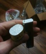
liveforphysics, I'm not sure I understand what you're describing. Maybe it's a different type of cap. I only worked with film. For wound film caps, there's no question that a low aspect ratio shape (hockey puck) results in lower ESR than pencil-shaped. All of the parts I worked on were custom, costing from a few hundred to several thousand dollars for a single capacitor unit. Certain customers will pay that much to get higher performance & have the parameters customized to their application, so I know how to manipulate the design parameters to affect performance.

View attachment film cap sketch.JPG

2 caps2.jpg

see thru2.jpg

I dug out my junk box to see if I could find a cap to put on my ESC. They are all scrap that was going to be thrown away. I thought there might be some that were good electrically, but just scrap because they were off cap, or a down rev prototype, or something like that. Unfortunately, they are just about all bad electrically. I had plans to use the film for a non-electrical purpose. I found one that is 1.3 mOhm, but it's the size of a cigar box.

Is the "plate material" you describe the endspray - labeled "sprayed area" in the sketch & the gray ends of the caps I'm holding with the lead sticking out of one of them? That's not part of the capacitive element, it's just the end connection. Some people call it "schooping", & it's pretty cool in its own respect. It's basically spray painting with semi-molten metal. My boss used to do a parlour trick if we gave a tour. He'd stick his hand in the spray right in front of the noisy blowtorch.

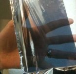
ESR for a film cap would be 2x (lead resistance + lead to endspray connection + endspray resistance + endspray to film connection) + dielectric losses + the resistance across the metallization on the film. The last one usually dominates all the others combined. Resistance across the endspray is probably the least significant. The endspray is about a millimeter thick. The metallization on the film is many orders of magnitude thinner. You can easily see through it in the picture. It's so thin that the thickness isn't even measured directly. It's rated in ohms per square. A high aspect ratio cap has higher ESR because the current travels further through the thin metallization. The fact that it travels a longer distance across the endspray is insignificant.

spinningmagnets, I know how to make it to meet spec requirements, but I'm not used to finding it in a catalogue. I never worked with catalogue parts. I'll try to find one, but what I'm used to will be expensive. All the voltages used for ebikes would take the same film cap. Don't bother looking for anything rated under around 100V since it isn't made. Polypro has a dielectric strength of hundreds of volts per micron, & the thinnest it's commercially available is about 3um, so they are all high enough voltage.

Something like this would get you down to 10 mOhm or better, & shouldn't be too expensive:
Polypropylene dielectric.
Heavy metallization (low ohms/square). Heavier is lower ESR, but somewhat less reliable since it doesn't "clear" or self heal as well.
Low aspect ratio

Better, but more expensive:
Foil leads (instead of wires).

Lower ESR but larger & more expensive:
Wound with double metallized polyester film & polypro dielectric instead of metallized polypropylene.

Even lower ESR, but even larger, even more expensive & no clearing ability:
Wound with solid metal foil.

Still lower ESR, even larger and more expensive:
An array of multiple cap elements in parallel connected to common foil or bus bar terminals (effectively making just one very low aspect ratio cap).

If you still have money left over, swap PTFE for polypro.

Somewhere down this list the ESR of the capacitive element will become smaller than to the ESR of the conductors between the cap & what you are trying to filter, so you'd have to get more creative with the system as a whole to see additional benefit. I'm not sure which one I'd pick - need help from one of the sparky's to finish spec'ing the requirements. What should the capacitance be for this application? Is there any practical benefit to getting super low ESR & ESL, or is it all the same as long as it doesn't blow up?
 
In that film cap design, I 100% agree short and fat is the way to go for low ESR. Electrolytics are quite the opposite of film cap construction with respect to leading and aspect ratio effecting ESR, as they don't spray the ends, they just spot weld the leads in the center of the foil strips before rolling it up.
 
Thanks for posting EDS. Even if a new option doesn't pan out for me, it can be educational, and I am definitely still learning. I was only curious because Digikey has about 50,000 capacitor choices, and if you don't know what you're looking for, you might only be one letter/number away (in the search window) from a good choice.

Most of the builds that have added caps, seem to only need two or four of the $2 variety. As long as those are working OK, there's not much incentive to find something that may be better in some way.
 
Here are the three cap choices I had selected after much study and searching. When comparing cap choices, impedance/ESR should be as low as possible, and amps (ripple capacity) should be as big as possible (dont ask me why they list it that way). The lower the voltage rating, the better the performance specs are, but if the cap voltage is too close to your systems top-voltage and it spikes up over the cap rating, the cap will pop open like popcorn (also if you plug it in backwards...don't ask how I know that).

I'm told the uF number (physical size) of the cap doesn't help us at all (bigger is not better), its only the other numbers that are of concern.

12 mOhm, 4.28A, 35V, 3900uF, http://search.digikey.com/scripts/DkSearch/dksus.dll?Detail&name=493-1602-ND
16 mOhm, 3.32A, 50V, 1000uF, http://search.digikey.com/scripts/DkSearch/dksus.dll?Detail&name=P12393-ND
17 mOhm, 3.50A, 63V, 1800uF, http://search.digikey.com/scripts/DkSearch/dksus.dll?Detail&name=565-1731-ND
26 mOhm, 3.86A, 100V, 820uF http://www.digikey.com/product-detail/en/100ZLJ820M18X40/1189-1048-ND/3133977
27 mOhm, 3.51A, 100V, 680uF http://www.digikey.com/product-detail/en/100ZLJ820M18X40/1189-1048-ND/3133977
capacitor 001.JPG
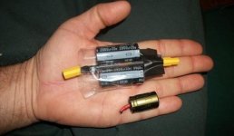
The two big caps on the pigtail are the 35V with slightly better specs than the 50V and the 63V. I am told 5V of ripple is bad, and with no added caps (just the two tiny ones from the factory) I was getting 4V of ripple with HARD acceleration.

I am told the most effective place to put the additional caps is as near as possible to the ESC on the power wire (red/black) inputs. Putting two the caps on a pigtail in-between the battery and ESC (4" from the ESC) still managed to drop the ripple to 1V (Not bad for $4 + shipping, recieved by mail in 5 days).

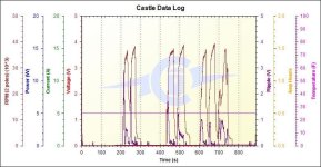
As you can see from the pic, the two 35V caps are twice as big as the 50V cap next to it in my palm (those are the only sizes Digikey had with the "best" specs). There is not a big difference in the specs, so today I tried the 50V caps on my 24V system to see if they would be slightly worse. On the Castle-Creations ICE-75A ESC data-logging, the brown peaks are the motor RPMs. I made two accelerations at the normal rate up to a stable speed of 20-MPH with NO added caps, and the result was 3V of ripple (it was 4V with hard acceleration).

I plugged in ONE of the 50V caps and made two more runs, and the purple graph line shows it lowered the ripple to 2V. I plugged in TWO of the 50V caps, and made two more runs, the result being the ripple reduced to 1V (six test runs, then I rode home). Although these runs were made with normal acceleration (ESC programmed for soft start) I no longer feel the need for the larger 35V caps at all.

After also considering the minor differences in the listed performance of the 50V and 63V caps, I would definitely use the 63V caps on 44V-48V system, rather than risk the 50V caps on a battery fresh off the charger. However, be aware the 63V caps are about the same size as the larger 35V caps in the pic.
capacitor 001 - Copy.JPG

I am 180-lbs, level/flat/dry road with no wind, friction-drive on a fat 26" rear tire, using an Exceed 63mm diameter motor with a 295-kV and a 1.25" roller, 24V SLA pack (reading 26V), E-Sky servo-tester as a throttle. Data-logging showed I was drawing 60A on hard acceleration (1:26 reduction-roller/tire) and about 10A at top-speed cruise. If your system draws more amps than this, you 'might' need more caps than me to get the same result.

From deardancer: http://endless-sphere.com/forums/viewtopic.php?f=2&t=5644&p=84577
...I put an oscilloscope on the various wires. To my surprise I found wild voltage swings, fairly high frequency spikes on the Battery positive line at the brushless controller; on a "constant" 26v input we had + spikes reaching over 50V and negatives going below ground. about 20 microseconds in width if I remember...This was a 24v Cyclone internal controller, but am suspicious that this might also be true of other controllers...Anyway, adding noise suppresion caps of sufficient size and voltage right at the controller incoming voltage line, and taking his accessory voltage tap closer to the pack, solved his problem...

Lukes lab: http://endless-sphere.com/forums/viewtopic.php?f=30&t=22582#p328568

CCCapPack2.jpg


http://www.endless-sphere.com/forums/viewtopic.php?f=28&t=7992&start=925#p285835
from recumpense: "...You want the caps as CLOSE TO THE BOARD AS IS HUMANLY POSSIBLE!!!! I mean, even 5mm of added wire increases inductance the the FETs. So, get those babies EXTREMELY close to the board (ESC inputs)...."

http://www.endless-sphere.com/forums/viewtopic.php?f=28&t=7992&start=975#p295154
from AJ/Kim "...I sorted the voltage ripple problem I was having by the addition of a single capacitor ~1 inch from the board on the input wires, max ripple was 7.6V, now its 3.4V..."
 
Thanks for this thread luke!
 
What about this alternative? The PEG226 series is intended for automotive applications. It is stocked by Mouser, but not Digi-Key. They have a low-enough ESR, and they have a really nice thermal design. The datasheet provided by Mouser includes additional thermal parameters, including total heat capacity and heat transfer coefficients. When the cap has a good heat sink, the ripple current rating goes up to the high teens.

These are all 63V rated caps:
MFR P/N, ESR (warm, high freq), max current, capacitance
PEG226MG3370QE1, 19 mOhm, 13.6A, 330 uF
PEG226MH3470QE1, 17.5 mOhm, 17.3A, 470 uF

What's the catch? The terminals are an axial design, so it isn't an ideal form factor with standard e-bike controllers. Oh, and one more tiny little thing, hardly worth mentioning: the can is electrically connected to the negative lead.
 
Putting some big MLCC caps in parallel with the electrolytics might be helpful. They are way more expensive, but can handle huge ripple currents without heating. It might make for a much smaller setup too.

Is the ripple current at the commutation frequency or the PWM frequency? I guess it would tend to be a combination of both, but I'm not sure which one is more important.
 
Is the ripple current at the commutation frequency or the PWM frequency? I guess it would tend to be a combination of both, but I'm not sure which one is more important.

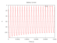
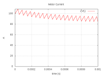
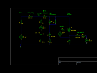
This is an interesting question. I coded up a spice simulation of a buck converter using parameters similar to what might be found in such a bike controller, and this is what I came up with. I think the answer is that the PWM ripple current is more significant, and the reason is due to the inductance of the battery pack and cables. I played around with some inductance calculators, and end up with a range of 100-500 nH of input inductance to the controller. At this level, the input filter caps endure an enormous amount of AC current.

The schematic and simulation were built using GNU gEDA and ngspice, so in principle anyone can build on this sim.

Unfortunately, if this cap current is accurate, then these controllers would be vaporizing the input filter caps on a regular basis. Since that clearly isn't happening, something must be wrong with the sim. The only way I can come up with a significantly lower cap current is if I lower the input inductance to less than 50nH, which just doesn't seem reasonable.

bat_current.png
Battery Current. RMS=74A

View attachment 3
Cap current. RMS=31A

motor_current.png
Motor Current. RMS=93A
 

Attachments

  • snubbers-schematic.png
    snubbers-schematic.png
    9.7 KB · Views: 11,668
  • snubber-sim.tar.gz
    2.6 KB · Views: 246
Back
Top