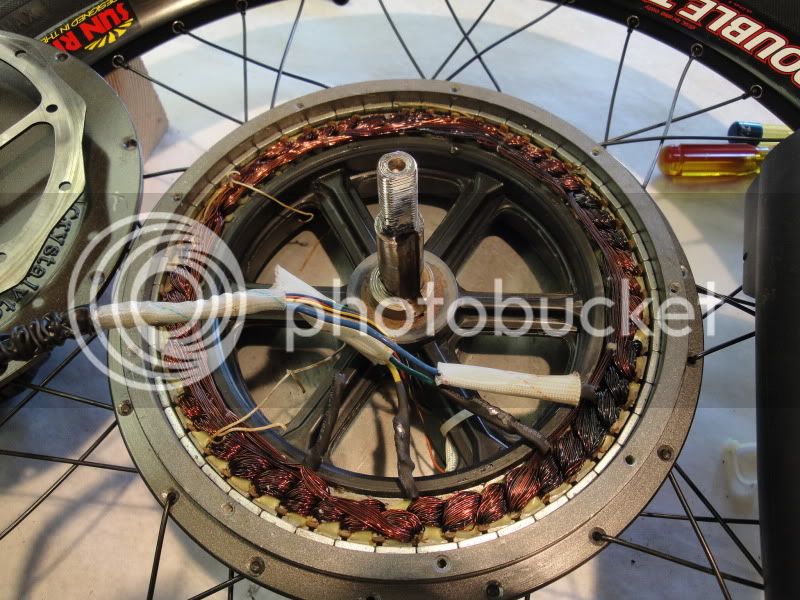
New Crystalyte Motor series (HT35 / HS35 and HT24 / HS24)

Methods, i totally agree with you!
unfortunately it is easier said than done. Especially in Europe. Hopefully after some time when the situation will establish, Kenny wont have more orders than production capacity ect...
Now it smells like a monopoly, more demand than supply + people do believe that new HS / HT outperforms pretty much any other motor.

I did ask crystalyte europe to press Kenny for that but they dont care. If i said I won't buy the controller unless it is with CA cable or a motor with hall sensors, they will just apologize and won't care at all.
There is a different mentality here in continental europe. As strange as it may seem.. England is totally different.

But you need to place a big order to be able to demand. And strong negotiation skills.
 
A quick look at Edwards instructions gave me this for a Crystalyte throttle:

Pin 1: +5V (red)
Pin 2: Ground (black)
Pin 3: Throttle Signal (Green)
Pin 4: Battery VCC- or to the ignition wire (thin red wire) from the controller (blue)

Hope this helps.

@ Planky

that means i need a 4 pin throttle, cause mine from Justine is 3 pin.
On the controller ot says throttle is 4 pin female so... didn´t know there are 4pin throttles ore maybe i can rewire the 3 pin to fit the 4 pin.

Thanks
 
regarding CA, why not just buy the motor/wheel from kenny but then buy the controller from lyen? lyen sells sensorless controllers with a CA plug...or am i missing something here?
 
groundproximity said:
A quick look at Edwards instructions gave me this for a Crystalyte throttle:

Pin 1: +5V (red)
Pin 2: Ground (black)
Pin 3: Throttle Signal (Green)
Pin 4: Battery VCC- or to the ignition wire (thin red wire) from the controller (blue)

Hope this helps.

@ Planky

that means i need a 4 pin throttle, cause mine from Justine is 3 pin.
On the controller ot says throttle is 4 pin female so... didn´t know there are 4pin throttles ore maybe i can rewire the 3 pin to fit the 4 pin.

Thanks

I would just try using pins 1 to 3 before thinking about a different throttle. :)
 
HALL SENSOR INSTALLATION EXEMPLE


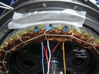
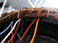
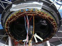
Here is pictures of one HT35 i modified for a friend here in Quebec:

Instead of pulling completly the stator, i partially pulled it just enough to let me have enough room to work on the hall sensor location.

Please note that as opposite of the X5, the hall sensor location is ON THE SAME SIDE than the phase wires connections!

( I used DP420 epoxy.. but any other epoxy should work) and also some 26 gauge TEFLON wires capable of 260 celisus.

The most difficult part was to pass the wires under the winding.. I used long nose grip to pull them one by one under it.

I also installed 10AWG turnigy silicon wire for each of the 3 phase.

The room for wire i the slot of the axel is smaller than on the old great X5.. it is actually 100mil narrower!.. so to cary 5 litle hall sensor wires pl;us the 3 x 10 gauge wires.. i had to work hard!..

I used grease on the wires to let them slide easy on the bearing of the side cover.

Everything worked perfectly the first time i tested ! :mrgreen:

Doc
 

Attachments

  • P1080423_800x600.jpg
    P1080423_800x600.jpg
    105 KB · Views: 6,374
  • P1080424_800x600.jpg
    P1080424_800x600.jpg
    78.1 KB · Views: 6,319
  • P1080425_800x600.jpg
    P1080425_800x600.jpg
    103.7 KB · Views: 6,374
Doctorbass said:
HALL SENSOR INSTALLATION EXEMPLE

I also installed 10AWG turnigy silicon wire for each of the 3 phase.

The room for wire i the slot of the axel is smaller than on the old great X5.. it is actually 100mil narrower!.. so to cary 5 litle hall sensor wires pl;us the 3 x 10 gauge wires..
Doc
I cannot believe you could fit there 3x 10awg wires!
Have you dremeled some more space in the slot for this?? :?:
I could only fit 3x12awg teflon wires and 6thin ptfe wires for halls and thermo-sensor and that was pretty hard to do!

72e6b75d524b.jpg


edecca3754cb.jpg
 
Hi sorry to sound dumb but can somebody please explain in detail how to open a hs motor? I have taken the screws out etc but that's as far as I have got. Do you need a puller and if so what do you attach the puller forks too as the unit is smooth and doesn't seem to have anything to get some leave ridge from. Also if you are using a puller is the puller screw shaft in connection with the electric cable side or the disk rotor side? Is is possible to take both sides of the covers off? Any info would really help pictures would be a real help including a video etc. Thanks
 
Webbo said:
Hi sorry to sound dumb but can somebody please explain in detail how to open a hs motor? I have taken the screws out etc but that's as far as I have got. Do you need a puller and if so what do you attach the puller forks too as the unit is smooth and doesn't seem to have anything to get some leave ridge from. Also if you are using a puller is the puller screw shaft in connection with the electric cable side or the disk rotor side? Is is possible to take both sides of the covers off? Any info would really help pictures would be a real help including a video etc. Thanks
http://www.endless-sphere.com/forums/viewtopic.php?f=2&t=28988&p=418147&sid=46b963c88267cbe543c48e4e677b9f3b#p418147
 
andreym said:
Doctorbass said:
HALL SENSOR INSTALLATION EXEMPLE

I also installed 10AWG turnigy silicon wire for each of the 3 phase.

The room for wire i the slot of the axel is smaller than on the old great X5.. it is actually 100mil narrower!.. so to cary 5 litle hall sensor wires pl;us the 3 x 10 gauge wires..
Doc
I cannot believe you could fit there 3x 10awg wires!
Have you dremeled some more space in the slot for this?? :?:
I could only fit 3x12awg teflon wires and 6thin ptfe wires for halls and thermo-sensor and that was pretty hard to do!

72e6b75d524b.jpg


edecca3754cb.jpg

Yes.. it worked!.. 3 x 10 AWG wire! ( the turnigy silicon 200C)

It was hard but it finally worked!!.. the trick is to put grease on the inside diameter of the bearing and on the wires skin!

Also.. pay attentin to the amount of silicon you put arounhd the winding for your hall sensor! :shock: too much silicon will make the winding to heat up more! . The silicone is an insulator.. and will block air flow around that part of the winding! If it blow.. i'm sure it will be around this area if you leave too much silicon in place :wink:
 
I prefer to let the hall sensor wires on top of the winding instead of through the inside, I think on top is more airflow for cooling the wires, inside is more thight to eachother and less airflow. Any thoughts ?
 
Chaps,
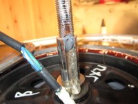
I just fitted my HS35 (stock) to my bike and have noticed that the power cable seems to be rubbing on the inside of the hole in the cheek plate as the wheel rotates. I'm in two minds whether to open it up and investigate (worried I'll break something) and running it as it is in the hope the sheath wears away a bit and the problem goes away (worried it'll fail instead). Has anyone else come across this? Does it matter? It is definitely rubbing as the cable moves a bit if I rock the wheel back and forth, it also makes a rubbery squeeking noise.
Cheers
 
mylittlepony said:
Chaps,
I just fitted my HS35 (stock) to my bike and have noticed that the power cable seems to be rubbing on the inside of the hole in the cheek plate as the wheel rotates. I'm in two minds whether to open it up and investigate (worried I'll break something) and running it as it is in the hope the sheath wears away a bit and the problem goes away (worried it'll fail instead). Has anyone else come across this? Does it matter? It is definitely rubbing as the cable moves a bit if I rock the wheel back and forth, it also makes a rubbery squeeking noise.
Cheers

Remove the black plastic wire holder. Regrove it 180 degress from the old hole and reinstall. When you remove this piece and look at the motor side of it they made the grove come away from the axle. Which lets the wires rub the seal. When you regrove and rotate it it holds the wire tight agianst the axle
 
Why are so many people converting their hs motors to sensored? I thought the best setup was to go sensorless what are the pros and cons. The crystalyte 72v sensorless controllers are meant to work perfectly with the hs series so what's the attraction for sensored?
 
Webbo said:
Why are so many people converting their hs motors to sensored? I thought the best setup was to go sensorless what are the pros and cons. The crystalyte 72v sensorless controllers are meant to work perfectly with the hs series so what's the attraction for sensored?

Main benefit is the ablity to heavily overvolt and overamp the motors. Apparently sensorless controllers cant handle the higher power that some of these guys are running. Also i think i read that a sensored controller is slightly more economical and also allows a lot better dead starts under load.

Thats my take on it though, cant see much of a benefit for us people that intend to run the motors within spec, i.e. less than 2kw.
 
shawn_1976 said:
Remove the black plastic wire holder. Regrove it 180 degress from the old hole and reinstall. When you remove this piece and look at the motor side of it they made the grove come away from the axle. Which lets the wires rub the seal. When you regrove and rotate it it holds the wire tight agianst the axle

Nice!
You are absolutely right.


Webbo said:
Why are so many people converting their hs motors to sensored? I thought the best setup was to go sensorless what are the pros and cons. The crystalyte 72v sensorless controllers are meant to work perfectly with the hs series so what's the attraction for sensored?

Lol... the propaganda is taking hold.... :D

The information is all here friend - read the forum. For one thing - try stopping on a steep hill. When you try to restart it will be very rough. For a second thing - a sensored motor can work with 100% of controllers on the market (even sensorless) while a sensorless motor can work on only a very tiny fraction. A brushless controller needs feedback from the motor (in the form of halls or BEMF) to be able to drive the motor... it is like stepper motor. The better the feedback the easier it is for the motor to sync up - especially when starting from a dead stop. DOUBLE especially when starting from a dead stop with a heavy load.

-methods
 
Thanks for the info. Looks like my hall sensor slots on my hs35 are on the other side (non wire side). Would this make a difference in how I mount the sensors? Would the signal wire be the same way round as if it was mounted on the wire shaft side? Can I also ask why the hall sensor wires are placed underneath the coil wires ( very hard to do) and not on top?
 
nicobie said:
As in most things mechanical It just took some dicking around but I finally got the cover off.

As you can see the windings are fried. 2 out of the 3 phase wires have shorts to the stator. :( It looks like I got a dud. I wonder if there was a small short from the start and that is what caused it to make those horrible noises? Notice that only one segment of the windings are really black.

I was using a new Lyen 12 fet 4110 controller that was set for 45 battery amps and my CA was showing about 47a when it blew and at 90v I don't think I was shoving too many watts through it. I was on flat ground and had less than 1.5 miles on it.

I figure I can't just buy a stator so it looks like I am in the market for a new motor (again). I really want another HT35 as I think It will be perfect for my use. If the one I melted ran as good as it did, I wonder what one that was put together properly would be like? I am going to get on my knees and grovel at methods feet and beg for him to sell me another one :mrgreen:


DSC01730.jpg


When I noticed a light scraping noise on one of the newly potted motors, I got curious and opened it up again because I thought too much epoxy potting had been applied and was rubbing against the side cover.
What I found was this --->


:shock: Maybe that could have been a cause for the above :?: :?:
 
electricwheels.de said:
When I noticed a light scraping noise on one of the newly potted motors, I got curious and opened it up again because I thought too much epoxy potting had been applied and was rubbing against the side cover.
What I found was this --->

Damaged Winding.JPG

:shock: Maybe that could have been a cause for the above :?: :?:

That's bad news all right, I had it happen to my first hub a few years ago and it blew the controller out when it did. Of course my motor was from golden motors a few years back and looked as thought it was a badly refurbished hub from a previous customer. They had forgotten to put enough internal washers to prevent side to side movement of the axle, so eventually the windings rubbed on the side of a cover and shorted out just like yours. Of course my hub was a POS GM motor, but yours should have had much better QC than that! Hope you get some compensation from xlyte for this...
 
Doctorbass said:
Everything worked perfectly the first time i tested ! :mrgreen:
1) Doctor Bass, since you are the X5 'record man', could you please do a comparison of these new motors with the X5? Maybe you have already? Is there a thread or post with your comparisons and opinions? I searched, & I'm surprised I didn't find your post(s) about this comparison yet! :cry: (Or, is the 5404 your new "dream cream" motor? :lol: :twisted: )

2) Also, was this sensored upgrade worth the effort? What did your friend gain by doing this upgrade specifically?

3) Is this hall-sensored mod just as quiet & silent running as the sensorless controller?

Thank you (edit for Arlo1 post below: documented race track & bus puller) X5 record man! :mrgreen:
 
deVries said:
Thank you X5 record man! :mrgreen:
What makes him X5 record man there is plenty of others with some insane power to the x5 motors as well... I have to force air through mine or it melts :mrgreen:
 
ZapPat said:
electricwheels.de said:
When I noticed a light scraping noise on one of the newly potted motors, I got curious and opened it up again because I thought too much epoxy potting had been applied and was rubbing against the side cover.
What I found was this --->

Damaged Winding.JPG

:shock: Maybe that could have been a cause for the above :?: :?:

Hope you get some compensation from xlyte for this...

Compensation from Crystalyte??? :lol: :lol: :lol:
I am not suppose to open it, as I loose my guarantee when I do so.
The motor is new and has not even run yet, so I have the cover machined out @ my own expense and carefully isolate the windings again.

But I wonder what one would do if one hears a light scraping noise when you have unpacked and fitted your brand spanking new motor... :shock:
If you run it, it might self-ignite after a couple of hundred meters, destroying all evidence in the process. :?
Send it back to your dealer? More delay? :|
What exactly is one to do?
 
Opened mine today. The two plastic covers have sharp edges indeed.

View attachment 2

I did alot of dremel smoothening, resoldered the cable and reinforced the cable with additional shrink tube. That in return needed alot of grease to get the cover on again. With sanded plastic covers the reinforced cable and dremeled axle it should be okay.

Cable after opening. I´m afraid that was not only caused by the opening process...

IMG_2297.JPG


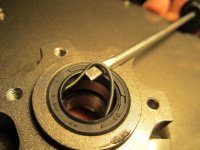
Anyone knows what this circle spring is for?

IMG_2301.JPG

The stock anderson connections from the motor cable easily slid of the metal crimp just by applying a little force so i considered soldering the motor cable to the controller - anyone done this before?
One pair of connectors that could loosen up or fail less.
 
Back
Top