Mounting Turnigy Watt Meter

Slightly off topic, but has anyone else noticed the amps reading on the Turnigy is out by about 300mA?

I had it hooked up to monitor charge going in a battery and it was reading 0.00A but the battery was still charging so that's when I hooked up my DC current clamp meter and it reads 300mA.
 
Earlier in this thread you'll find mention of the calibration trimmers - http://endless-sphere.com/forums/viewtopic.php?f=2&t=21976&start=15#p350612. Being out of whack is pretty common on these meters, but they can usually be adjusted to give close to the right figures.

Jeremy
 
:oops: Thanks for that Jeremy, that makes calibrating them a lot easier.
 
Hi. This is my first question on this forum. I would like to install turingy watt meter on my bike but I have a crazy idea and need your advice. Instead of desoldering shunt and wires I am thinking about using a dremmel tool and cut the part of the PCB with shunt and thick wires away. This would be save a lot of time, at least it seems so. It doesnt look like there is any other leads on this part of the PCB instead of those with shunt. I will appreciate your opinion on this. Thanks and thanks Jeremy for great idea on this!
 
Thank you Jeremy.

It was a snap and works as described.
I spread the boards apart and un-soldered the shunt - relatively easy and got the polarity right the first time around.
I have the early version and rather than upgrading to v2 I will hold off till I can get a CA.

I so much appreciate all the creativity here at ES.

Cheers,
Roy
 
Wattever,

Can you repost how to fix the problem with the wrong amp readings? I keep getting 157amps after doing the remote shunt mod. I hope this doesn't mean I fried my turnigy.. just got to use it today once :[

Edit:
It was reading weird before that too.. basically I would hold the throttle and then it would read the normal 2amps.. but it would slowly drop back to 0 even though I'm holding the throttle. Before I did the shunt mod, it kept reading 2amps under throttle. So I tried rewiring the whole thing, and that's when it started reading 157amps even when only the meter was hooked up to the battery but not the motor.

edit again:
tried hooking it all up, seems its just the current thats off. voltage reads fine, and its apparent that it really isn't 157amps.. in which case i'd say byebye to my lifepo4 if that were true. glad its the turnigy thats reading it wrong and not some short circuit.
 
Bump..
any help?

I tried playing with it, and I got it to stop saying 157amps. However, it'll jump around from 1amp to anything up to 6amps.. depending on where I place the leads on the shunt. Can anyone shed light as to how this shunt works? I can't seem to find a place to solder the leads and still give accurate readings anymore.
 
I managed to screw mine up trying the mod, constantly reads ~135amp doesn't change
the voltage is correct though, any ideas how i managed to get it wrong? would connecting the negative and
positives ass about be the cause possibly? I was going to swap them but ho8ught i would post and ask also...
's a series of pics i took while doing the mod, i also just lifted the LCD out of the way. This Turnigy
also has a mod on it to increase the voltage it can read, done by an ES member (soz i forget the nickname)

Turnigy_Shunt_Mod.jpg

Thanks in advance for any help fellas...

KiM
 
The little shunt itself is not polarity-sensitive; it's basically just a piece of "wire".

If solder flows on the shunt beyond the pads on the end, I can imagine it would affect the readings, especially if it ended up all the way across the shunt, but if it's only on the original pads for the purpose, it should be fine.

If the wires from the shunt to the pads on the meter PCB are long and really thin, they could have a bit of internal resistance that might slightly affect the reading, but so little current flows thru them that it is nearly irrelevant. However, they *could* pick up RF noise or induced currents from other things, so twisting them together along their length, or using existing twisted-pair wire, should help to minimize that.

If there is a lot of induced RF in there, a tiny ceramic capacitor at the PCB end of the wires might help; not sure what value but in the pF range, I'd guess.

Other than those things, I don't see where having the shunt outside the unit should make any difference to it.


It is of course possible that static electricity (ESD) from your body discharging into the meter's circuits during the mod process could damage things, making them act wierd, but many circuits have at least some protection against this. I don't know if that design does.
 
My voltage also reads correctly. The amps, I got it to not read 157amps constantly by removing the solder and resoldering one end (the negative controller side first) and then I touch the other end (negative battery side) to the shunt. That made it read anywhere from 1-6amps, it would jump around. I'm guessing if I soldered it down, it would be constant, but would not be zero when it should. That's why I'm wondering how this shunt works.. I figured its just a piece of wire with very low resistance, and the two negative leads should be able to be soldered to it without much trouble. Guess I'll remove the shunt and start dremeling/grinding off some solder and redoing it extremely neatly. Can't think of much else that'll help make it work.

Btw, I've learned that the positive lead can be connected pretty randomly anywhere, as it only powers the turnigy. The negative leads with the shunt is the headache part and should be done extremely carefully the first time around to avoid any future headaches.

More help would still be appreciated though, I can't seem to get my shunt soldered correctly :oops:
 
Here's another way to do it.

wattmetermount.jpg


wattmetermount_2.jpg


Not as cool as the handlebar mount, but no flexing wires to worry about etc.
I opened up a watt meter to see what needed to be changed out and said to my self... F this! :evil:
 
Ideally I'd like mine to have a quick plug so I could remove it when parking it at school, don't want any theft problems. Had I known this "quick" shunt project would turn into a headache I would've just purchased large plugs. However, if I can figure this out, the added benefit of using remote shunt is that I wouldn't HAVE to have the turnigy mounted and plugged in to ride the bike, and I could use it when I feel like it which isn't all the time.
 
I actually had another go at mine yesterday unfortunately all i can report is the same story
the meter reads something like 157amps soon as i turn it on, only thing remaining correct
is the voltage, least i have some form of monitoring i guess haha...

If you guys figure it out someone pm me please ;)

KiM
 
That seems to be the universal problem. These shunts are so fine tuned that I think any solder getting in between the wires and shunts is going to mess up the readings. Unfortunately being as my bike is my DD to school, I can't keep messing with it to fix it. That's why I'm hoping someone knows a definitive fix to this problem.
 
I replaced the supplied/installed shunt with this; http://www.altestore.com/store/Meters-Communications-Site-Analysis/Shunts/100A-100Mv-Shunt/p4637/
It works fine.
 
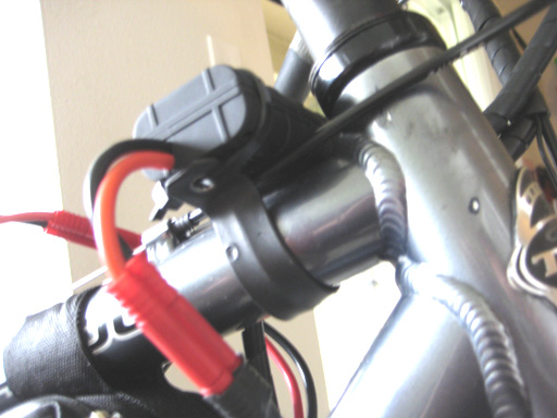
Out of interest i hooked up my old Drain Brain (Early Model CA) To the Turnigy shunt
and be blowed if it was all zeroed (cept volt reading that was correct) and when i applied throttle it proceeded to work! now
im aware the shunt isn't calibrated for the CA so the readings are out by how much i have no idea...
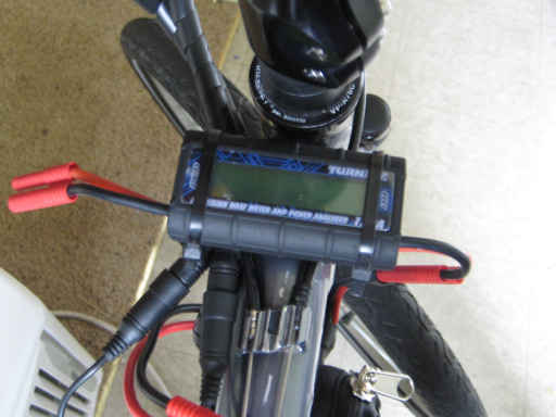
WOT is pulling around 150watts which was about correct for the ol cruisers reduction drive/sprocket
setup... anywayz, i have some form of monitoring with the volt reading so know when the packs getting
Low, till i can afford something better shall suffice :) Have hit YPedal MaN
for a CA hopefully the 'MaN' has an oldie laying about i can pickup for a reduced price on new CA ...

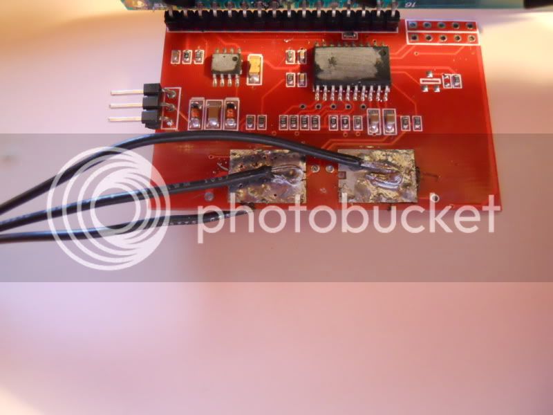
I was also thinking about the wire i have used and whether this will make a big difference to the readings?
Jeremy suggested using some 3 core wire, i had none so used 3 strands of thicker wire than what
is present in 3 core wire, i have some 3 core now i might if i get time run a lead to the Turnigy from the shunt
and see how much or if the readings differ much due to smaller gauged wire being used....what did
y'all use for connection wire from shunt to meter?

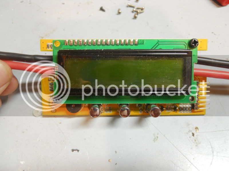
Mark F how did you calibrate the shunt to your Turnigy to ensure correct readings? Just hooking it up
isn't enough.

KiM
 
Mark F, did you have to solder the connections or is that shunt a screw on type?

I can get my shunt to work correctly.. resoldering it (or even just shifting the shunt wires) changes the amp readings from the dreaded 157amps, to something like 2 or 3amps. I haven't had the chance to mess with it much, but plan to do a clean resoldering of the shunt with shunt wires when I replace my current AC type plug coming out of the battery with a MIC cable plug so it doesn't keep falling out and sparking when I hit a hard bump on the road.

Does anyone know how much the pots can be adjusted in terms of # of amps? If I can solder it and keep it at like 2amps, will I be able to adjust the pot back down to zero amps?
 
If your amp reading is flying there - you probablly just need to solder your shunt wires again, take a good look at the shunt's pad.
DSCN0543.jpg


When the shunt is soldered on the board the shunt connects the big wire pads with the small pad - you need to connect the two with soldering iron.

left side soldered good, right side - not!


* this is true only with the older Turnigy WattMeters boards.
 
For those that want to do the cheaper meter, I posted a how to do it here based on Jeremy's instructions:
http://www.pedelecs.co.uk/forum/electric-bicycles/7340-remote-watt-meter-13-less.html
You can make a nice mount for it by making an aluminium bracket that replaces the original side-plates and mounts to the stem head. A similar bracket could be made for the Turnigy meter
DSC00027.jpg
 
You can see space on the right solder board that was dry and free from solder. See on the left solder covers the whole pad.

D8veh, thanks for posting that! I have that meter because the good one was out of stock forever when I tried to order it.. I will try to modify this new meter! Thanks!
 
Is it that part that needs to be connected to the big pad?

Cause I got rid of my 157amps reading not be resoldering that pad but by simply unsoldering it from the shunt and moving it around in different places.

http://i55.tinypic.com/y007t.jpg
 
Yes, that is why my meter wasn't working.

I wanted to do a remote shunt mod with this meter, the HK010, but I decided not to. I have a different version of the meter than shown in your post, which I purchased from hobbyking 4/15/2011. The shunt is in a really bad spot to try to get out and it is a different type of shunt than in your meter. :(

DSCN0734.jpg


DSCN0735.jpg


DSCN0738.jpg


DSCN0737.jpg


And if anyone wants to maybe get this meter, I wouldn't recommend it because it doesn't store peak readings, just real time.
 
I'll open up my watt meter and see if that's the problem with mine.

Your other watt meter looks terrible to do remote shunt mod, especially how you can do it without taking off the screen on the turnigy, looks like its all crammed in there on that one.

Will post back, hopefully that's really the problem and I will be able to use my turnigy again!
 
Back
Top