Beta CA build for R/C controllers

Justin,

Since most High Voltage RC controllers are optically isolated... I would think providing a 5v rail could be very useful and eliminate the need for an additional 50.00 HV Battery Eliminator Circuit. Personally I build a Resistor Divider network to lower the potential input to a useable range for LM317T and then configure it for a 5v output... this is good for about 1A which is more than adequate for hall throttle power, small servos, LEDs, etc... I've blown far too many CC BEC Pros to go back :)

Any chance (wish list) of having an input to trigger shifting back and forth from Wye to Delta? I ask because then your CA could also guarantee 0 throttle until the motor comes to rest and then engage the Wye / Delta shift before ramping the throttle back up - would prevent the dead shoot through I know some have experienced and could even setup the shift point to be automated - electra glide (an ongoing project for me now, one I would happily abandon if you wanted to pick it up).

Regards,
Mike

PS: Im also available for beta testing if needed, I have an HV110 and ICE 120 and 160s on builds now... in addition to Wye / Delta on my MS eDrive v4 in progress now. Also have a Kepler drive assembled but not installed with multiple motors for it (could send it your way if you want a test platform).
 
Great work Justin. This is a a very exciting solution that I can see will sell very well. Looks like there are plenty of beta testers already but I am keen to purchase a pre production unit also. I am keen to test this in my latest drive design and see this as a great alternative to the interface I am working on especially for people who still prefer a twist throttle rather then a button throttle.

In relation to the Turnigy motor, These motors are surprisingly robust and although not the most refined motor out there, they are great bang for your buck at around $50.00 USD
 
mwkeefer said:
Justin,

Since most High Voltage RC controllers are optically isolated... I would think providing a 5v rail could be very useful and eliminate the need for an additional 50.00 HV Battery Eliminator Circuit.

OK, thanks for the confirmation. Do you know how much power do the ESC's without a battery eliminator typically draw from the 5V line? It seems like a pretty negligible current in the castle creations controller. Any more than 5-10mA of current draw from the CA's bus will cause the backlight to get quite bright. I would probably put an absolute max of 15mA, which means 7mA for CA, 5mA for hall throttle, 15mA for BEC replacement = 27mA through backlighting LED.

At these currents the max voltage of the CA is also reduced because it is generating a lot more heat through the regulator, but still fine for RC systems which are rarely over 50V.

Any chance (wish list) of having an input to trigger shifting back and forth from Wye to Delta?

There aren't any available I/O pins in the circuit board so probably not in the way that you envisioned. How is the delta wye switching accomplished? Is this being done electronically with large relays or with a manual DPTT toggle? If it's done electronically, then it would be possible to send a signal that pulls the Vi throttle input to GND regardless of what the user is doing, pauses for a bit for the motor to spin down, then activates the relays to reconfigure the windings, and then re-enables the the Vi signal path.

However, I do wonder about the necessity of this since delta wye switching itself is rather pointless when you have a speed controller. You add all kinds of mechanical complexity and don't get any more intrinsic torque from the motor when switching between delta and wye. If the goal is higher speed then use either a higher voltage pack or higher KV motor. If the goal is to have a high torque Wye mode and a high speed Delta mode, then it's misguided. If the goal is to have two speed modes that each still operate at 100% duty cycle since the tiny caps on RC controllers can't sustain PWM ripple currents, then it's a lot cheaper and easier to add more capacitance to the controller bus than to switch the high current phase windings on the fly.

Then you do your two speed modes electronically via the ESC if that's the objective, or am I missing something?

Justin
 
Justin,

ESCs which don't have a 5v rail (HV type) only use the 5v for signal ground in essence and draw no current really, the throttle adapters, eliminators or MCU type modulators / controllers pull a tiny bit of current... I think most halls embedded in throttles require 20ma (or actually that's the limit of current running through them, it can be lower).

With regard to D/Y switching, when using an RC based system like an Astro 3210... the most efficient gearing (when the motor is in wye mode) is around 22-25 mph maximum. This provides hill stomping and launch torque in abundance but... it's a bit slow for use between towns where speed limits (in my area atleast) are 35 - 40mph and the roadways are flat... Once you go to jump between towns 22-25 doesn't cut it anymore, that's when having D/Y and kicking into D mode helps out a bunch... yes it's torque / 1.73 but it's also kV * 1.73 (and no load currents, etc)...

In my example the kT (W) is 8 (or 9)... 1.73 : 1 lower in delta but still a useable amount for fighting wind resistance (all you need worry about above 14mph) and runs about 40mph (43 on paper). Since most of the time I am only in need of 25mph until I travel on these higher speed roads with far fewer hills and serious inclines.

My build produces approx 22,291 in oz of torque at Zero in Wye mode or 116 ft lbs of torque... that's for the 0-25 mph run, add a shift to delta and the torque falls off to: 116 / 1.73 / 2 = 33.5546 ft lbs @ 25mph which is half of the delta max speed... so plenty of torque to push me to 40ish but not up large hills, that's with 120A limiting.

I hope this explains my position on D/Y a bit better... my current implementations are what I call Phase Locked Relays (fancy way to say I monitor the motor till it stops before altering the circuit to Delta and reconnecting to phase output of controllers), that's where most people tend to have failures.... where Wye doesn't disconnect completely before Delta engages which causes shoot through and dead shorts.... adding a trigger which waits for motor RPM to = 0 first is the safe way to shift. In my case, the motor side of my reduction first stages ceases to move within 1 -2 seconds of throttle interrupt.

Most wont care either way but I prefer to have a highly efficient 25mph "gear" and the ability to cruise the wide open flats at 40mph... I am still working on a solid state FET based D/Y switching method but the best place to do this would be the controller, sadly none i've ever seen support such features so it's down to DIY solutions.

Whew, way more than I wanted to type so late :)_

Regards,
Mike
 
rodgah said:
I would be interested in it for sure!

Hey guys, so I finally got a temporary store site setup for the beta RC Cycle Analyst, so for those wanting to purchase the device and give this a try you can do so directly here:

http://www.ebikes.ca/store/store_rc.php

The price is the same as the large screen CA-LDPS device, or $125, but to be complete you will need some kind of shunt with the system for the current sensing. The molded inline shunt is certainly most convenient for those running in the <2kW power levels. Otherwise in a pinch it would be possible to tap into a length of the battery ground wire if you aren't too concerned about the overall current accuracy. 6 inches of 10 AWG wire is about 0.5 mOhm. I did list a proper 0.5 mOhm shunt on the website as well, but it's probably larger and heavier than the actual ESC device.

I'll have a batch of 15-20 of these made up during the week and they should be able to ship by this coming Friday.

Naturally, this is also a beta testing program, so part of the point is to get a spread of systems that are field testing the device to help find glitches or improvements that need to be made. I'm hoping that it will mostly work out as I've implemented things, but until If there are situations that require reprogramming the firmware, then you may have to ship it back here to be reflashed, (or if you are familiar with in circuit microchip programming and have the necessary programming tools, we can send the updated .hex file directly). As well, I don't expect there to be any hardware complications with the CA sending a PWM servo pulse to the ESC, but until we have a number of systems you never know.

So, just understand that.

-Justin
 
Just placed my order. Thanks Justin.

Looking forward to giving it a go.

- Adrian
 
+1 Thankyou Justin shall report back on how it works out :)

KiM
 
+1 of everything :)
Justin, let us know what to collect for information durring testing :)
Regards,
Mike

PS: Althought I do have all needed MCU flashing HW, you are correct in assuming the PPM signal (its PPM not PWM) generated should work fine, provided that you hand off the recurrance of signals to the MCU itself (some abstract PWM functions)... in other words, it will work great as long as your MCU isn't tied up too terribly with other functions to cause a miss in timing output (guessing you checked it out on a scope?).

My atmega based ESC throttle adapters do great work, I can't see the new CA version being any different (you use a faster than Atmega MCU right?).
 
Warren,

I think you will need to run the Ground (for reference) and the signal line down to the ESC input on the HV160 ICE but .... it may even need the +5v to power the input stage to power the optocouplers on the input side, this is an assumption but you can try ground and signal first alone and it may be sufficient to get it working :)

Regards,
Mike
 
The Castle 160 will definitely need 3 wires from the CA for it to work as it needs +5V, ground, and signal.. ESC's with a built in BEC will just need the signal wire from the CA for it work.

Justin, will the Beta version have protection so that the ESC BEC +5V doesn't conflict with the CA +5V or is it just up to the end user being fully aware of the wiring requirements?
 
mwkeefer said:
PS: Althought I do have all needed MCU flashing HW, you are correct in assuming the PPM signal (its PPM not PWM) generated should work fine, provided that you hand off the recurrance of signals to the MCU itself (some abstract PWM functions)...

OK, I was mostly concerned about the hardware aspect, since ground referenced signals in the face of high current mosfet switching currents and whatnot can be prone to glitches. But it sounds like the actual PPM input on the ESC board is typically opto isolated? If so that makes me feel a lot better.

in other words, it will work great as long as your MCU isn't tied up too terribly with other functions to cause a miss in timing output (guessing you checked it out on a scope?).

The CA's PPM output can't miss a beat since it's tied to the primary 25mS main loop and that never fails to execute. However, the output goes to 0V steady once you enter the setup menu and are playing around with stuff, and then it resumes pulses as soon as setup is exited.

-Justin
 
mwkeefer said:
Warren,

I think you will need to run the Ground (for reference) and the signal line down to the ESC input on the HV160 ICE but .... it may even need the +5v to power the input stage to power the optocouplers on the input side, this is an assumption but you can try ground and signal first alone and it may be sufficient to get it working :)
Regards,
Mike

Mike is correct. The HV160 does require both 5V power and GND for the ESC input signal to work.

Justin
 
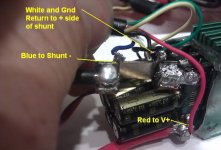
So I had a chance today to try wiring up a Castle Creations HV160 controller with a 6-pin connector to make it effectively just like an ebike controller with a CA-DP plug. Since the controller doesn't have any onboard shunt, I soldered a parallel pair of the ~1.4 mOhm shunts we use in the stand alone CA directly to the - battery lead. So the net RShunt value is a tad over 0.7mOhm, and it should be able to handle 100 amps no problem.

Leads for the shunt, Gnd, and V+ are wired up as follows:

Castle Controller DP Connections.jpg

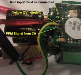
Then for the signal wires, it was quite easy to piggy back the CA-DP cable 5V and PPM lines right on top of the solder pads for the original servo cable. In this case I had a schottky diode on the 5V line, so it was only receiving about 4.6V and still working fine. It was also important to tie the Gnd of the servo input to the Gnd on the shunt, otherwise the input signal pulses have no ground reference and they won't register to the ESC:

Castle Controller DP Connections Top View.jpg

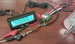
The net result is a controller that is simply plug and play with the CA-LRC device, and it will work fine with or without the CA plugged in. This is definitely the tidiest approach to getting all the signals from the controller to the CA:

RC CA with direct plug fired up.jpg

The Astro Flight motor here had way less no-load current than the Turnigy, about 0.7A, and with a smaller shaft that was harder to slow down, so it wasn't quite as easy to test the current control loop but from what I was able to get it seemed to work fine again. Since the 3-pin servo connector was left unused, it made it easy to stick the scope probes in and watch the pulses change width as I applied and removed load from the shaft in an effort to maintain constant current draw.

www.recumbents.com said:
Wow this is a great idea! Plug the throttle into the CA and then just one wire down to the ESC. Should this eliminate need for both the BEC and the servo tester when used with a Casle Creations HV160?
As the above pictures should illustrate, with a bit of wiring on your electronic speed controller it sure does!

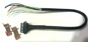
I'll throw in a few of the shunts and one of the short 6 conductor cable with mating female 6-pin connector to plug into the 6-pin connector on the CA, so that anyone will also have the parts to wire things up as depicted here.

CA-DP Cable and Shunts.jpg

Thank you Justin!
-Warren.

Thanks for all the feedbacks and encouragement, it's been good to see there are a number of people interested in this, and I hope it'll be able to live up to the hopes!
 
Kepler said:
Justin, will the Beta version have protection so that the ESC BEC +5V doesn't conflict with the CA +5V or is it just up to the end user being fully aware of the wiring requirements?

I'm going to include the schottky diode in the wiring that is internal to the CA, so that the user doesn't need to be aware whether their controller has a BEC or not. I don't imagine any of the non-BEC controllers will take issue if there is only 4.6V on the line instead of 5V.

-Justin
 
justin_le said:
I'll throw in a few of the shunts and one of the short 6 conductor cable with mating female 6-pin connector to plug into the 6-pin connector on the CA, so that anyone will also have the parts to wire things up as depicted here.
.

This is outstanding Justin, bloody legend mate
definitely makes for a HEAP less wiring running willy nilly
all over the bike! I ordered me a CA and a BIG shunt from you
looks like the big shunt will be tossed in the draw now haha...

Even more excited for the CA to be delivered now!

KiM

p.s any chance you will build yourself up a "RC" motored bike in the near future Justin?
 
So since I am not a electronics guru, does this fix the low speed burnout problem that the R/C controllers have at high load? It would seem like it limits current draw right, so it SHOULD?? or no? I would LOVE to shrink the controller size in my bike to 1/4 of its current size, and have 100A safely on tap!!! Right now with the gears available 45A is crazy!
 
It has current limiting and a low speed limit that can be set before power is applied. Between the two features, it should make the RC controllers pretty reliable. I'll be ordering a few of them for sure as soon as I'm able to. I think this will be a popular item!
 
Justin, you are so good at this stuff, why not make a complete controller that includes the CA? I would think it would be a big hit!
 
Whiplash said:
Justin, you are so good at this stuff, why not make a complete controller that includes the CA?

I would if someone would take over the heavy task of running this business and grant me 2 months of uninterrupted development time! The technology especially on the microcontroller front has improved quite a lot since the last time I did this (complete controller) back in 2008:

Original Cross-Canada ControllerCross Canada Regen Controller.jpg

So it would be exciting to have another stab at it with modern hardware and actually make a single universal controller that works with any and all motors, sensored or sensorless, wide operating voltage, and at any RPM. Maybe it'll be a quiet enough winter for that :wink: .. -Justin
 
Delegate.

When I had my wholesale food distribution business I actually abandoned my commercial driving licence so I couldn't drive a truck anymore. Business doubled in 12 months. If you don't already have one, get a good business manager and hire/train somebody who can handle the technical questions that must swamp you on a daily basics.

Now I actually feel guilty bugging you about that Clyte controller/CA problem I have. :oops: If you can't get to it until winter, it will be fine with me. In fact I'd rather have you develop your new controller than get my Clyte controller figured out.

Your service is so good that maybe people (like me) are taking advantage of you.

Nick
 
AussieJester said:
I ordered me a CA and a BIG shunt from you
looks like the big shunt will be tossed in the draw now haha...

Actually it's good to have the large shunt as a very handy current reference. The smaller inline ones have about a +- 15% resistance variation around a nominal 1.35 mOhm each, so you can temporarily hook up the big shunt in your circuit and use the voltage drop across that to calibrate the smaller ones, or to calibrate the RShunt for any other -DP style CA.

p.s any chance you will build yourself up a "RC" motored bike in the near future Justin?
Nah, I don't like the whiny noise, and if I I'm gonna have a vehicle that has additional gearing complexity it'll be on something much sillier like this:
http://www.unicyclist.com/forums/showthread.php?t=89581
 
This looks great - less wires & less boxes always good.

I have just placed my order for one.

Thanks. :D
 
Back
Top