Automatic anti spark circuit

avandalen

100 W
Joined
Oct 2, 2010
Messages
175
Location
Maastricht, The Netherlands
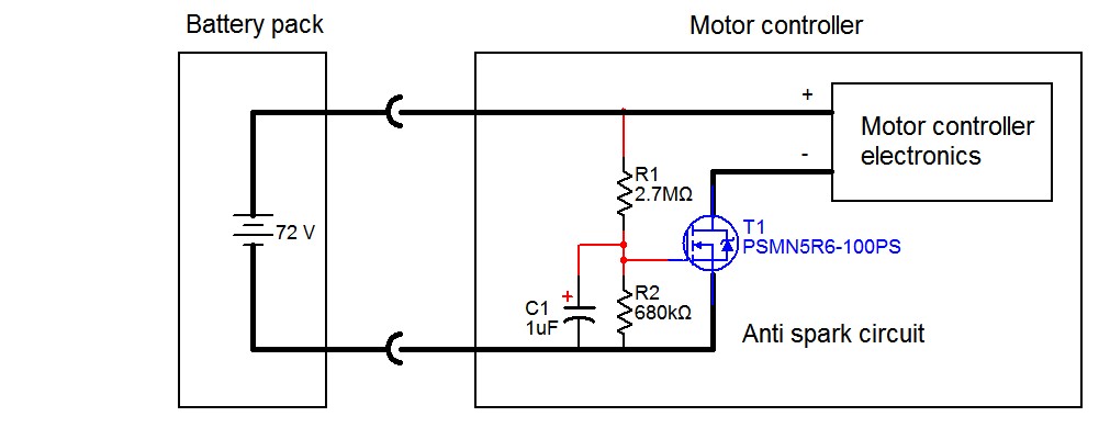
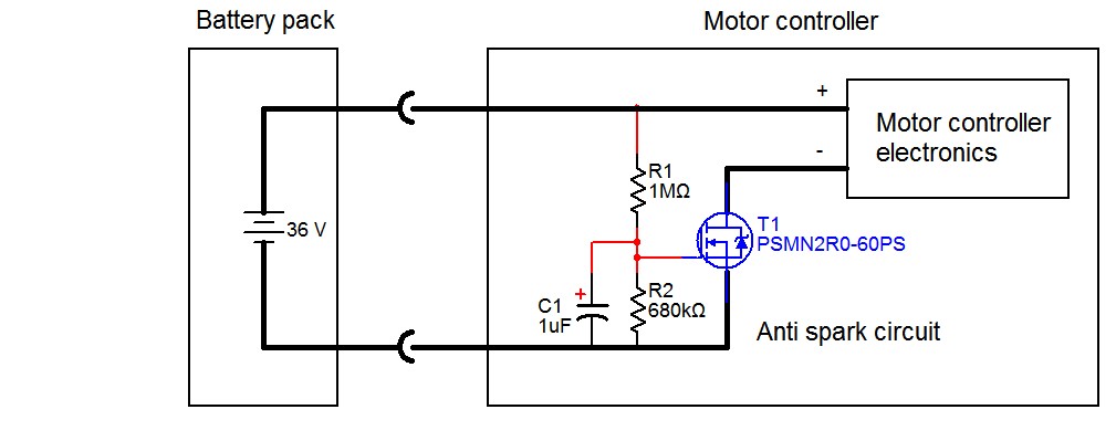
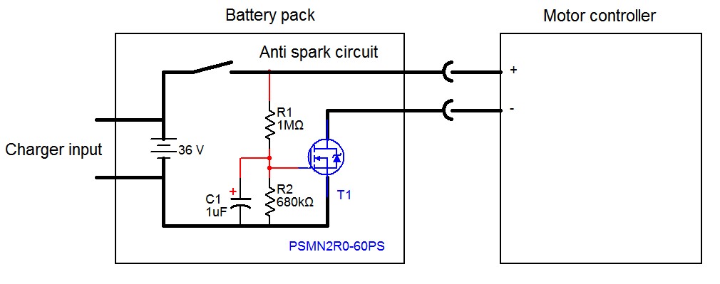
Here is an anti spark circuit which works automatically. Just simply insert the connector, no sparks will occur. The anti spark circuit can be built into the battery pack or into the motor controller.
Automatic-spark-eliminator-circuit-top.JPG

Spark-eliminator-circuit.JPG

Spark-eliminator-circuit-built-into-battery-pack.JPG

Read more here:
http://www.avdweb.nl/solar-bike/electronics/motor-controller.html
 
Very nice. Can this circuit work for 72v and How much current can it handle? Do you plan on making the pcb and parts available as a kit?

Thanks,
Ambrose
 
Useful but if you are going to put a MOSFET in the current path which will introduce loss (all be it small) and more importantly cost you might as well also use it to provide reverse polarity protection at the same time.

Edit: Just thought about it a bit more and unfortunately I now don't think both can be combined :( for polarity protection you need to use the body diode in the same direction and the normal current flow so you can't reduce the current by much so it won't work unfortunatly. Its too late, I'm off to bed.

I wouldn't see this circuit as practical for very high current setups due to MOSFET cost but for say < 50A setups (with correct mosfets) it would be ok.
 
I worry about the losses as well. With a low power setup you might be able to get away with it, but otherwise a high-power relay or contactor is really the only way to go.

Edit: although when you're not switching, at steady state the losses wouldn't be too terrible. Might be able to get away with $20 in FETs.
 
Great idea, but I would need that MOSFET to be able to carry 100Amp at least... that is what my CA regularly gives as a peak current.
 
I'd be worried about heat on the TO-220 tab and where its going to mount so it doesn't melt anything too.
 
I wouldn't say that 50mV voltage drop at 10A is negligible, that's 5W 0.5W power dissipation on a non-heatsinked TO220. That's a lot of heat. But it is a very nice solution for lower power controller!

update: corrected the power dissipation, it's 0.5W and not 5W
 
Forgive my electronics ignorance, but is stuff like the pathway from battery + through R1 and R5 to battery - a common thing for you guys? I realize that it's still only less than .5W for my typical pack charge of 80V when I'm parked, but I only disconnect a few times a year, so a parasitic loss like that could be really bad if I didn't ride for a long time. Controllers don't have anything like than in them as long as they're turned off do they?
 
ambroseliao said:
Very nice. Can this circuit work for 72v and How much current can it handle? Do you plan on making the pcb and parts available as a kit?

Thanks,
Ambrose

You can use another power Mosfet for higher voltages. No PCB is required, see image. For currents above 10A it is better to use more power MOSFETS parallel or MOSFETS with a lower on-state resistance such as the IRFB 3006PBF 60V / 2.5mΩ.
 
Njay said:
I wouldn't say that 50mV voltage drop at 10A is negligible, that's 5W power dissipation on a non-heatsinked TO220. That's a lot of heat. But it is a very nice solution for lower power controller!
Yes I know, 10A gives 0.5W power loss (not 5W). Here in the Netherlands the maximum motor power is just 250W, so the current is <10A. You can use mosfets with a lower on-state resistance also. The circuit can't be used for kWatt motors.
 
John in CR said:
Forgive my electronics ignorance, but is stuff like the pathway from battery + through R1 and R5 to battery - a common thing for you guys? I realize that it's still only less than .5W for my typical pack charge of 80V when I'm parked, but I only disconnect a few times a year, so a parasitic loss like that could be really bad if I didn't ride for a long time. Controllers don't have anything like than in them as long as they're turned off do they?
Yes I know :? , the circuit is already replaced! See the website.
 
avandalen said:
Njay said:
I wouldn't say that 50mV voltage drop at 10A is negligible, that's 5W power dissipation on a non-heatsinked TO220. That's a lot of heat. But it is a very nice solution for lower power controller!
Yes I know, 10A gives 0.5W power loss (not 5W). Here in the Netherlands the maximum motor power is just 250W, so the current is <10A. You can use mosfets with a lower on-state resistance also. The circuit can't be used for kWatt motors.
You're right, sorry, my mistake! Did the calcs like if 50m were resistance. Nevertheless, even 0.5W is a lot of heat; in my experience, half that is enough to heat a TO-220 to be finger burning.
The motor has situations, under load like starting or going up a hill, where it will pull (probably a lot) more than 10A. Keep in mind that heat generated is proportional the square of the current.

Oh, and hey, I like your "assemblage", I'm also a big fan of non-standard circuit assembly!
 
Nevertheless, even 0.5W is a lot of heat; in my experience, half that is enough to heat a TO-220 to be finger burning.
.[/quote]
http://www.kennethkuhn.com/students/ee431/thermal_homework.pdf
"A power transistor in a TO-220 package is typically rated at 25 watts dissipation
when attached to an infinite heat sink at 25 C. How much power can it dissipate
in free air at an ambient of 25 C? Answer: note that the thermal resistance from
junction to ambient (no heat sink) is 3 + 45 or 48 C/W. The maximum junction
temperature in the infinite heat sink case is 125 C (3 + 1 = 4 C/W total). Thus, the
maximum no heat sink power dissipation is 2.08 watts {(125 –25) / 48}."
 
avandalen said:
...Here in the Netherlands the maximum motor power is just 250W...

With ebikes becoming more common, is theft of batteries becoming a problem? I'm just wondering what is the reason for frequent battery disconnect, or was this a puzzle you wanted to elegantly solve? Here they'll steal anything that isn't bolted down, but other than a rare lead powered cheapie ebikes are an unknown, so the low-life thieves don't understand the value of batteries, and I have little concern. Once ebikes become common so values are known and a market for the stolen stuff develops, then I'll have to worry, though I think I'll go with built in batteries on my ugly but highly functional ebikes.
 
John in CR said:
With ebikes becoming more common, is theft of batteries becoming a problem? I'm just wondering what is the reason for frequent battery disconnect, or was this a puzzle you wanted to elegantly solve?
Not everyone can charge their bike in their living quarters, many must remove their batteries and bring them up a flight of stairs.
 
rebelpilot said:
Njay said:
Nevertheless, even 0.5W is a lot of heat; in my experience, half that is enough to heat a TO-220 to be finger burning.
http://www.kennethkuhn.com/students/ee431/thermal_homework.pdf
"A power transistor in a TO-220 package is typically rated at 25 watts dissipation
when attached to an infinite heat sink at 25 C. How much power can it dissipate
in free air at an ambient of 25 C? Answer: note that the thermal resistance from
junction to ambient (no heat sink) is 3 + 45 or 48 C/W. The maximum junction
temperature in the infinite heat sink case is 125 C (3 + 1 = 4 C/W total). Thus, the
maximum no heat sink power dissipation is 2.08 watts {(125 –25) / 48}."
The thing is that you don't the silicon at 125ºC when Ta is 25ºC (and Ta in this case is inside the controller) nor the device very hot touching or heating other stuff and the air inside the controller... It's not just a matter of what the device can handle. If you look at TO-220 MOSFETs datasheet you'll see that Tja is usually 62ºC/W max.

Nice homework by the way :D
 
Nice pictures and well thought out as always sir. I'm lucky in not needing to ever disconnect the battery from the controller. If something like this must be done, I believe a circuit the pre-charges the caps and then has a relay switch on a short time later (or a couple relays depending on power requirements) would be much better. MWkeefer does something like this using a 555 timer ic. This would actually be a product that might sell decently here!
 
Njay said:
I wouldn't say that 50mV voltage drop at 10A is negligible, that's 5W 0.5W power dissipation on a non-heatsinked TO220. That's a lot of heat. But it is a very nice solution for lower power controller!
update: corrected the power dissipation, it's 0.5W and not 5W

Use the PSMN2R0-60PS (2.2mohm). The power loss just 0.22W at 10A. You can also put some MOSFETS parallel. Note that the contact resistance of an ordinary toggle switch can be much larger than the MOSFET on-state resistance.
 
I described my way of doing this here: http://endless-sphere.com/forums/viewtopic.php?f=3&t=40142#p586436

I found that even for low current use there was a big benefit in using several FETs in paralell, just to keep the temperature down in the FETs. My first version used a single IRFB4110 on a bike that only drew around 14A max and that got uncomfortably warm in use. The present versions with several paralleled FETs barely get warm at all, even at much greater current.

The other thing to watch is the gate resistance. Using high values, as in that circuit above, makes the gate prone to interference. I found that the FET switching time was fine at just a few tens of mS, there is no need to have a long delay as the FETs turning on gradually allows the peak capacitor charge current to be kept at a low value - the worst case is only the first mS or so of turn-on, anyway so you want the FETs to transition reasonably quickly to being fully on.
 
36Volt system typically means that there is 10 x Li-Ion cells in series reaching 3.6V x 10 = 36volts. However when cells are fully charged their voltage is 4.2Volts i.e. pack voltage is 42Volts. In this circuit, with the given resistor values, gate voltage in fully charged situation reaches over 20volts which exceeds the maximum GS voltage.
 
Vgs will reach Vbat * R2 / (R1 + R2), so at 42V it will reach 17V.
The resistive divider shown for the 36V system scales Vbat to ~40.5%
 
Back
Top