A PIC based Battery Management System

file.php


fechter said:
The resistor in series with the FET to act as a shunt needs to be a much lower value, like a few ohms.

When the shunt FET activates, it will throw the voltage measurement off because it's in the same string. The voltage monitoring needs to be separate from the shunt.

You need to keep the FET gate at the right voltage relative to the source. You need either a optocoupler or a floating FET gate driver.
:arrow: Part One: Yes, the resistance values need to be fiddled with. No big deal.

:arrow: Part Two: No, that's not a problem because you do voltage measurement on separate cycles from balancing. Maybe every one hundred cycles you stop and take a voltage measurement... maybe even let the cells rest for a few dozen cycles to let the voltage settle down. That's easy with software.

:arrow: Part Three: This might be a problem. So you think that the gate voltage needs to be relative to the source voltage. Hmmmmmm.... so if the source at that point in the series of cells happens to be 32 volts you need something like a gate voltage of 36 volts to trigger the FET. That might be a problem. You think the old "common mode voltage" problem will resurface here? (just like with op amps)
 
the whole point of the low gate voltage fets was to be able to use an opto-coupler to use the individual cell's voltage to turn it on. you're also going to need to be able to measure the voltage of each cell while the fet is on and when it is off. then you can take about 256 samples and average them to get the average voltage of the cell depending on the duty cycle the fet is driven at, then you adjust the duty cycle to get the voltage where you need it, this seems pretty hard to get right, and you need to be able to drive all of the fets at the same time, so you are going to have to use a slow pwm frequency. it seems like this approach to balancing is going to be more expensive than the analog version, and much harder to get right. you could still get the same effect though, without any pwm, when the cell gets to 3.65V make the charger go into 100mA charge mode, that is the current the cell is considered to be done at when its at 3.65V, after you switch from high current down to 100mA the voltage of the cell will drop below 3.65V, and when it gets back up to 3.65V you turn on the shunt and that cell is done. this would probably take a lot longer to top off at the end though.

it will probably just be cheaper and better to use the analog shunts on each cell and use the MCU for other things, and to communicate with the charger. it can monitor the cells and set to charger into low current mode when it sees a cell get to 3.6V, and also do the LVC, it could also measure the current coming out of the pack for a battery level meter with an LCD display or something, show the voltage of th lowest and highest cell during discharge etc. plenty of stuff for the MCU to be able to do that would take a lot more money to do with just analog components.
 
FET Behavior

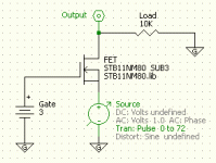
To say that a FET cannot work within the series string of cells appears to be in error. I ran a simulation of a FET and oscillated the source voltage from 0-72 volts and then took a look at the output. If the FET were to be unable to open as a result of a high source voltage we would see some difference between the created voltage and the output voltage, but I'm not seeing that happen. With a simple 3 volt gate voltage this particular FET (which was good at low voltage as I recall) had no problems letting all the 72 volts pass through without needing a gate voltage higher than 3 volts. (heat is a separate issue and that is dealt with by selecting the right resistor values)

:arrow: Comments?

Is the simple "Voltage Divider with FET" really the perfect circuit after all?


file.php
 

Attachments

  • FET Behavior.gif
    FET Behavior.gif
    3.5 KB · Views: 2,977
dirty_d said:
...you adjust the duty cycle to get the voltage where you need it, this seems pretty hard to get right, and you need to be able to drive all of the fets at the same time, so you are going to have to use a slow pwm frequency. it seems like this approach to balancing is going to be more expensive than the analog version, and much harder to get right.
But wait a second... I'm not sure you are grasping the concept yet. The idea is to loop using the PIC and so there is no PWM "per se" but there is an ability to stop the charging for a moment (since we obviously need to be able to control the charging process) and let everything settle down, maybe run a quick resistance routine to make sure our resistance measurements are precise, then run a quick check of the cell voltages. Remember that all this takes place at speeds that are hundreds of times faster than a second... computer chips run at speeds that are so fast you can do a lot of stuff in less than a second. So maybe you design the charging to charge for a few seconds, then stop, do all this evaluation, then continue. Before you continue you set the FET's to their appropriate open or closed status and you also calculate the amount of current you will drive through the system.

:idea: It all makes sense... once you see it... 8)
 
first off, you have the fet biased the wrong way, the drain is supposed to be positive relative to the source, the way you have it it looks be be conducting like a forward biased diode. the gate voltage required to turn it on is relative to the source.
 
dirty_d said:
first off, you have the fet biased the wrong way, the drain is supposed to be positive relative to the source, the way you have it it looks be be conducting like a forward biased diode. the gate voltage required to turn it on is relative to the source.
:arrow: Oh Crapola!

Yeah, you're right... and when I switch it around then it requires the gate to have a voltage slightly larger than the source in order to make it open fully. Arrrgh!

Placed backwards and it basically acts like a wire.... damn... scratch that one... :?
 
Back To The Optos... Again...

file.php


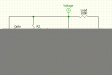
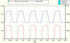
So I took this diagram (above) and made a functional imitation circuit using a simple battery source as the equivalent opto voltage input. This is how that looks. (see below) As a special note, I did try to increase the voltage and it seems to scale with higher common mode voltage, but you have to be careful about your resistor values, there seems to be an effect on BypassCurrent otherwise.

:arrow: When you take away the opto voltage you get no shunting activity.

I just don't see (hopefully yet... and not forever) how the PIC can be used to any kind of advantage here. If you use the optos and they are driven by the cell voltage then they shunt all by themselves. The PIC doesn't have anything to do. Unless the sole reason for existence of the PIC is just to know the cells voltage.... hmmmmm.... I suppose since the PIC could know the cell voltage it could drive the opto's. So you might be able to save having to use Difference Amplifiers. :?

I just wish there was some way to directly drive the FET gates and not have to use Opto's in such a round about way...
 

Attachments

  • FET Behavior Opto Diagram.gif
    FET Behavior Opto Diagram.gif
    4.6 KB · Views: 2,917
  • FET Behavior Opto Chart.gif
    FET Behavior Opto Chart.gif
    10.8 KB · Views: 2,916
The cell shunt gets turned on by the PIC. All the voltage measurements are done by the PIC and tell the shunts when to turn on and off.

In Gary's analog version,the zener tells the shunt to turn on. In either setup, the fact that the shunt is activated needs to be communicated back to home base so the charger current can be lowered.
 
fechter said:
The cell shunt gets turned on by the PIC. All the voltage measurements are done by the PIC and tell the shunts when to turn on and off.
:arrow: But is there any way to go without an optocoupler?

If the cell is in the middle of the series and maybe goes from 32.0 volts to 35.2 volts there's no way to insert the 3 volt PIC signal to open the gate without using the optocoupler to transfer it. That means that the base circuit would require as a minimum:

:arrow: Optocoupler
:arrow: FET
:arrow: 2 Resistors for a Voltage Divider

...which isn't terrible, but I'm not sure how easy it would be to mathematically include the behavior of the optocoupler if you wanted to do it all with software. I was figuring it would be complicated enough with simple resistors and now you would be adding a new twist that would make the math more challenging.

The voltage divider evaluation routine would (in my present thinking) send out a voltage one wire at a time. You would then record the voltage you got back on the other wires. From this matrix of data you triangulate back to know the resistance and voltage values. It's the "plucking of the guitar strings" that would tell you what you have.

Adding the optocoupler makes the logic more complex.

However... one idea might be to use the Analog to Digital conversion pins for the Voltage Dividers and then use the Logic I/O pins (that can't do analog) to open and close the gates by using the optocouplers. Since you are looping in the PIC anyway you can figure out ways to loop your way to a full cell by spacing the open verses close time of the FET as the charging tapers off.

So maybe this might be okay. :)
 
There are ways to drive the shunt transistor without using optocouplers, but they would likely be more expensive and more complex. A regular bipolar transistor might work out better in the shunt application depending on current.

The shunts would be 'told' whether to be on or off once each measurment cycle. With 8 or 16 channels of measurements, multiplying, subtracting, comparing, etc. any idea what the cycle time would be? Several per second I would guess, but I really have no idea.
 
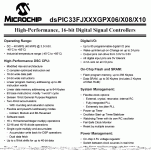
40 MIPS

fechter said:
The shunts would be 'told' whether to be on or off once each measurment cycle. With 8 or 16 channels of measurements, multiplying, subtracting, comparing, etc. any idea what the cycle time would be? Several per second I would guess, but I really have no idea.
:arrow: A "MIP" is a "million instructions per second".

But that doesn't mean that you can get a million tasks done in a second because every thing you do takes several instructions as a minimum. If you get down to the assembly language coding then you are staring at individual instructions and worrying about how fast it executes. For this application the 40 MIPS speed is abundantly adequate to code using higher level languages because if you have to slow down charging by some small fractional portion of a second it's not going to hurt anything.

My guess is that we can do a rough calculation of execution times. If we knew the cumulative values of the resistors in advance and had them stored into some data variable locations it would take one or two instructions to load the data and then about a dozen more to do a calculation on that data. Since that's just one cell's worth we need to do this for all the cells, so multiply by that amount. Then you have to figure that the Analog to Digital converter will take quite a few instructions to complete. Then add a bunch of other wasted cycles due to inefficient compiler choices. (though these days that might be next to nothing) Finally you would get:

2 * 10 * 20 * 10 * 10 = 40,000 instructions to evaluate the cell voltages.

But we are starting with 40,000,000 instructions per second, so:

40,000 / 40,000,000 = 0.001 second to complete.

This value might be a little higher depending on how much calculation you could do, so let's assume that we do 100 times more work as far as abstract math:

0.001 * 100 = 0.1 second

I would guess that a "worst case scenario" would produce a complete analysis of a simple voltage measurement and math calculation in less than a tenth of a second.
 
where are you getting 40 MIPS from? a 40MHz PIC runs at 10 MIPS because it takes 4 cycles per instruction, my guesss is that the instructions needed would be much higher than you estimated, these microcontrollers are 8-bit and don't have a floating point unit, so all the math on anything larger than 8 bits is emulated in software by the C compiler, i did a little test and on my 8MHz ARV that runs at about 8 MIPS it can do about 5000 floating point multiplications per second, and about 2700 floating point divisions per second, since floating point math is all emulated in software by the C compiler it takes many many instruction to just complete one simple line of C code like "a *= 1.02345;". on my AVR the ADC takes 13 clock cycles to finish a conversion, and you are going to want to take more than just one, to get an accurate result i take about 16 samples and add them then binary shift them right one place and you end up with an oversampled 12-bit result, then i do that a few times and average the 12-bit results the normal way, ive got very accurate and consistent results this way that have been near perfect according to my cheap multimeter's limited precision. many many cycles to do all this.

in the end i don't see the advantage of having the PIC do the balancing itself, using the LM431s looks to be a lot cheaper and seems like it would just plain work better.
 
dirty_d said:
where are you getting 40 MIPS from?

...in the end i don't see the advantage of having the PIC do the balancing itself, using the LM431s looks to be a lot cheaper and seems like it would just plain work better.
Well, the thread is about using a PIC for a BMS, so it's about our evaluating the benefits of the idea. (you can't know for sure the benefits unless you do a thought experiment to consider what might be possible)
 

Attachments

  • 40 MIPS.gif
    40 MIPS.gif
    34.9 KB · Views: 2,797
Question

:arrow: What would be the proper way to model the PIC's I/O pins?

I've been playing around with some simulations and realized the you can model them in a lot of different ways and I'm not sure which is correct. Would they behave like a resistor to some degree and also like a sink? They apparently can sink 4mA's. When you assert the pin and place a voltage is that going to behave like a voltage source?

It's hard to know if I'm making any progress on it until I get this model figured out... :roll:
 
Safe, I hate to break it to you, but I think you'll have a real hard time modelling a PIC circuit. We won't learn much from modelling the analog parts either. We know how to make them work.

I don't give up so easily on the PIC concept. It's a matter of optimizing the number/type of processors for a given number of cells and working out the interfaces. The voltage measurement and shunt activation are not difficult. The code is.

As far as the cycle time, it sounds like it should be able to go through a complete routine several thousand times per second, which is way faster than needed (that's OK). If it did 10 cycles per second, I think that would be fast enough.
 
fechter said:
Safe, I hate to break it to you, but I think you'll have a real hard time modelling a PIC circuit. We won't learn much from modelling the analog parts either. We know how to make them work.
Everything can be modeled.

I just was looking to model the way the pin worked... like does it sink current or is it a push-pull kind of thing. I'm sure it's in the spec (pdf) and could figure it out.

Spring is approaching so I'm starting to think that my self taught "Electrical Engineering Course" will have to wait until the middle of summer (when it's too hot) or next winter.

:arrow: From my perspective this project is (like many discussed here) placed back on hold...
 
Aloha, I posted in October about using a microcontroller as the core of a BMS/charger, etc. No one seemed interested then. Hmm.

I've been playing with some ATmel/Arduino chips and boards. They look to be a better choice than the PIC due to better language support and lots of available code and examples. And the availability of very inexpensive boards from a wide range of suppliers. The free/downloadable C compiler and development software is a major win too. Very fast code, no assembler necessary -- results in hours instead of days.

http://www.freeduino.org
http://moderndevice.com
http://www.arduino.cc
http://en.wikipedia.org/wiki/Arduino
http://www.freeduino.org/
http://www.ladyada.net/techproj/Atmex/index.html
http://www.adafruit.com/index.php?main_page=index&cPath=17
http://www.youtube.com/watch?v=PeScmRwzQho

If someone figures out a good/cheap way to monitor cell voltages we'll be in business (fetcher's resistor array sounded good at first, but can't quite see how it could work.) The other features that will start to fall out will be incredible ...

* Monitoring/logging/displaying all cell voltages will be simple and cheap
* Automatically logging to laptop/flash drive/etc.
* Most microcontroller boards already talk to PCs, so advancing in that
direction should be duck soup.
* Temperature compensation is simple.
* Making inaccurate or offset levels precise is simple and free.
* Changing levels, values, alignment points -- simple, quick and free.
* Adding new features -- simple, quick and free.
* Amps, volts, watts, distance, time -- any combination easy to access,
compute and use.
* Accurate `Gas gauge' easy to build.

Once the interface glue is built things will take off ...


Richard
 
I still like the idea... but we all have so many projects running in so many areas that this sort of thing tends to be discussed when there is a "captive audience" deep in the middle of winter.
 
safe said:
I still like the idea... but we all have so many projects running in so many areas that this sort of thing tends to be discussed when there is a "captive audience" deep in the middle of winter.

Solve the problem of monitoring cell voltage and this one will take off.

Developing code for the AVR chips is fast. And fun.
 
rf said:
Solve the problem of monitoring cell voltage and this one will take off.
:arrow: Cheaply.

Solve the problem of monitoring cell voltage cheaply and this one will take off.

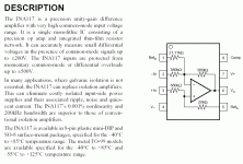
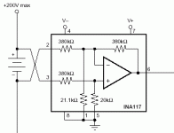
If you don't mind spending $5 per cell you could use a INA117 Difference Amplifier today and be sure it will work properly.


If you are in a hurry to get started I'd suggest buying as many of these as you have cells (for now) and take the $$$ hit for the time being so that you could develop the rest of the stuff. Eventually you could come back to the cell voltage question with a later upgrade in the software. I'm sure this whole project would take time.

Ideally we should start an OPEN SOURCE software development project and design the software collaboratively...
 

Attachments

  • INA117 Basics.gif
    INA117 Basics.gif
    23.7 KB · Views: 2,606
  • INA117 Information.gif
    INA117 Information.gif
    27 KB · Views: 2,605
  • INA117 Cell Diagram.gif
    INA117 Cell Diagram.gif
    4.5 KB · Views: 2,605
Hope this isn't duplication. A couple of thoughts:

If you have a simple solution for a small number (maybe 4-8) of cells, you could use multiple PICS (or whatever) and tie them together with SPI or I2C. more software, more fun?

In the extreme case of the above, one low voltage uP per cell. Then no comparator, no mux, no nothing. You will need sleep mode, and a reliable way to bus them to a master. Bet you could find a 14/16 pin uP with PWM for controlling the charge bypass for a couple of dollars.

Couldn't you just mux both positive and negative of each battery into a single comparator? The comparator provides the isolation, you don't have to worry about mux voltages, you get full scale (well, 5V anyway) resolution (maybe 10 bits is enough - i.e. ~ 5 mV), etc? You would need twice the mux chips, but you could find at least 16-1, so two chips for each 16 batteries. And with SPI/I2C, you could have as many as you wanted without worrying about I/O. What am I missing here?
 
Patrick,

That's lots of interesting new ideas.

One cpu per cell is a fun idea. I'd love to have a 16 cpu system in my battery pack :twisted: But getting them to talk to the bus will require optoisolators. So MCU+Opto per cell. Then you need extra components for balancing (at least resistor and transistor). That's not the simplest setup but still interesting.

I'm not sure I follow the idea using comparator? One comparator per cell? No voltage dividers between cell and comparator? Could you suggest some comparators that are reasonable cost and can handle 50V+? INA117/AD629 can do that, but not cheap.

Same thing with muxes. MCU with lots of ADC channels costs much less than an analog mux :) The most reasonable I found is DG406/407 for about $5 in small quantities. That's much less nice than mux fechter sugested (no overvoltage protection) but at 1/3 the cost.
 
Cell Based Solutions

From the larger perspective there is a strong argument for making the "solution" involve the cell alone and mostly skip the centralized PIC. All that a cell needs to do is:

:arrow: If voltage is low disconnect itself.
:arrow: If voltage is high disconnect itself.
:arrow: When disconnected act like a wire rather than a cell.

So the most simple way to solve this problem would be to use FET's of sufficient strength to be able to switch on and off and still be able to handle all the current. Such FET's are pricy... but it would make a good solution.

What I would like to see is a dedicated chip to come out of Silicon Valley that does what we want and have them sell it for a low enough price to make things practical. If those three qualities listed above could be achieved in a single chip then all you are left with is wiring the cells together and having a charger that can sense that it's done. (it just needs to watch the current and notice when the cells are dropping out)

By powering everything within the confines of the cell itself you eliminate the "common mode voltage" problem entirely. :)
 
Patrick said:
The comparator provides the isolation, you don't have to worry about mux voltages...
Except that high "common mode voltages" distort the comparators and make then so inaccurate that they are unusable. That's the reason for the INA117's they are custom built to deal with the problem of "high common mode voltage".

:?: Maybe we just need to accept a higher price plateau than we are used to... at least for the time being....
 
safe said:
Patrick said:
The comparator provides the isolation, you don't have to worry about mux voltages...
Except that high "common mode voltages" distort the comparators and make then so inaccurate that they are unusable. That's the reason for the INA117's they are custom built to deal with the problem of "high common mode voltage".

:?: Maybe we just need to accept a higher price plateau than we are used to... at least for the time being....


Perhaps there's a simple/cheap way to switch one diffamp between cells. Or a way to duplicate the expensive diffamps with cheaper parts.

There's an elegant solution out there somewhere ... I can smell it.


Richard
 
Back
Top