connections for? EcityP Smart S5-13 BMS

These Application Notes for OZ890 exist:

AN-1: "Battery Pack Assembly Sequence and Connections Technique"
AN-2: "Using the 4-Wire I2C Communication Interface"
AN-3: "External MOSFET Driver" describes how to drive the external MOSFETs
AN-4: "Using External Thermistor"
AN-5: "?"
AN-6: "Software Mode Guide" for use of OZ890 with a microcontroller "software mode"
AN-7: " OZ890 functions in multi-OZ890 Systems"
AN-8: "How to Do ADC Calibration"
AN-9: "PWM Discharge Application" describes how to use EFETC pin to implement the PWM control of the discharge MOSFET in Hardware Mode as well as Software Mode
AN-10: " EFETC pin used as power switch" describes how to use the EFETC pin as power switch and MOSFET switch
AN-11: "Application circuits for 5~13 cells Li-ion battery pack" describes the typical application circuits for 5S, 6S, 7S, 8S, 9S, 10S, 11S, 12S and 13S cells Li-Ion battery pack.
AN-12: "Sleep Mode Implementation in Software Mode"
AN-13: "Cell Balance Implementation in Software Mode"
AN-14: "Cell Disconnection Detection"
AN-15: "OZ890 PCB Layout Guideline"
AN-16: "Application circuits for Dual OZ890 system (OZ890 works in hardware mode)"
AN-18: "OZ890 Current Measurement Resolution and Accuracy"
AN-19: "Resolution and Accuracy of OZ890 Cell Voltage and Temperature Measurement and accuracy of OC/SC Protection"
 
rolf_w said:
the 'bleeder' LEDs are very helpful. did you solder them manually? tricky job...
Yes, it was very easy :wink:

rolf_w said:
ecitypower told me to remove CF13 to CF0 if cells are not connected and they did send me 0Ohm resistors as a replacement in case I would want to reuse these inputs again. i did ask for the reason but did not get an anwer yet. According to me this excercise could only make sense if the unused CFs are replaced with 0Ohm resistors in order to shorten/bridge the voltage sensing inputs of the unused cell positions...
For me with the schematic it's clear: the unused inputs should not be unconnected. So CFx is a capacitor if the input is used and a shunt if unused.

rolf_w said:
I also tried to figure out the current sensing circuit ; the 2 resistors are definitely not the shunt resistors ; i guess the circuit uses the Rdson of the power FET as a shunt to measure the current...
Oh yes, like Kelly does on their motor controllers !
And I think I/we will have a problem with this: as no curent will pass via the BMS it will enter in idle or sleep mode... will it go to normal mode in case of under/over voltage ?

rolf_w said:
what approach you have to build the i2c to usb interface? I will isolate the i2c bus of each board with an ADUM 1250 , link them all (currently only 2) to the same i2c bus connected to a PIC with integrated CANbus adapter...
I have just built it, it is a Phhilips Parallel Port to I2C.
The only difference to this schematic is the output pull-up resistors are connected to 3.3v supply from the BMS. The 5V supply comes from pin 1.
Know I have to find a PC with XP and a parallel port...
 
...For me with the schematic it's clear: the unused inputs should not be unconnected. So CFx is a capacitor if the input is used and a shunt if unused.
So we are of the same opinion: if cell#x is connected use CFx otherwise replace it with 0R shunt? Why not just short the unused input pins BCx?
...My boards are a little bit different from you: the CF0 and CF13 capacitors have been replaced by 0ohm resistors :shock:
Did I understand you correctly: you received a bms preconfigured for a 12s pack thus CF13 was shorted as well as CF0 with 0R?

...And I think I/we will have a problem with this: as no curent will pass via the BMS it will enter in idle or sleep mode... will it go to normal mode in case of under/over voltage ?
This might become a problem, according to DS:
  • transition full power> idle:
    No charge/discharge and No OV, OT, UT, OC, SC event occurs, No bleeding (if bleeding enable bit is set), No PF(VHPF, VLPF, CUPF, MFPF) event occurs for 5 minutes (Note: OZ890 can enter idle mode in UV event)
  • transition idle > full power:
    Charge/discharge or Any OV, OT, UT, OC, SC event occurs, Any PF(VHPF, VLPF, CUPF, MFPF) or Bleeding event occurs
  • transition idle > sleep:
    No charge/discharge and No OV, OT, UT, OC, SC event occurs, No bleeding event occurs (if bleeding enable bit is set), No PF(VHPF, VLPF, CUPF, MFPF fail) event occurs for 10 minutes AND Sleep mode support bit (bit5 of EEPROM 33h) is "1" (Note: OZ890 can enter sleep mode in UV event.)
  • transition idle > shut down:
    EFETC (External MOSFET control signal) shut down OR Host write shutdown

I presume charge/discharge event means a certain minimum voltage across the current sens terminals (SRN and SRP). If this is missing the OZ890 goes to idle mode and returns to normal mode according to the above conditions. However, I don't see a problem yet to stack two or more of the bms ...

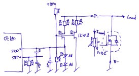
Here is a sketch of a quick reverse engineering job of the current sensing circuit in the SmartBMS. I do neither know if I got the components correct nor if the circuit is right and above all I have not much of a clue what this circuit should do - anybody else can guess?
SmartBMS_CurrentSens.jpg
 
rolf_w said:
...For me with the schematic it's clear: the unused inputs should not be unconnected. So CFx is a capacitor if the input is used and a shunt if unused.
So we are of the same opinion: if cell#x is not connected use CFx otherwise replace with 0R? Why not just short the unused input pins BCx?
I think It's just because the wiring to the battery is a little bit simpler, there is no need to connect the unused inputs to the last cell.

rolf_w said:
Did I understand you correctly: you received a bms preconfigured for a 12s pack thus CF13 was shorted as well as CF0 with 0R?
Yes !

rolf_w said:
I presume charge/discharge event means a certain minimum voltage across the current sens terminals (SRN and SRP). If this is missing the OZ890 goes to idle mode and returns to normal mode according to the above conditions. However, I don't see a problem yet to stack two or more of the bms ...
OK nice !

rolf_w said:
Here is a sketch of a quick reverse engineering job of the current sensing circuit in the SmartBMS. I do neither know if I got the components correct nor if the circuit is right and above all I have not much of a clue what this circuit should do - anybody else can guess?
I will have to scratch my head for a long moment :lol:
 
This parallel to I2C converter doesn't work (or the SW / driver), the data and clock lines have signal but it's definitely not an I2C protocol...
I will try to use a PIC.

Anyway apart from this, as the BMS is supposed to be programmed and the fact that not having current flowing through the MOS is not a problem, the bleeding should work.

What I see is that there is generally no bleeding, even with cells at 4.5V.
Sometimes, with cells at around 3.65v (the voltage I required), the bleeding is enabled. The number of cells that bleed varies: sometimes 2 or 3 and sometimes about 10... If i change the voltage a little bit lower or higher there is no more bleeding.

Do the bleeding is based on the voltage difference between cells and not only the cell voltage ?

I have some samples of MAX11068, the schematic is 75% done but I thought I will save time and money buying these boards...
 
This parallel to I2C converter doesn't work...
sorry to hear that. The one I bought from ecitypower is based on a 8051 uP..
I will try to use a PIC.
great, I would like to use a PIC for CANbus communication
no bleeding, even with cells at 4.5V.
the OZ890 can be set to bleed 'whilst charging' or whilst charging and in idle mode. In my test setup the OZ goes to idle mode (probably because it doesn't measure any current) thus I had to set it to bleed in idle mode!
Sometimes, with cells at around 3.65v (the voltage I required), the bleeding is enabled.
I have observed this too - but only for one cycle (=1s) ; probably an erratic voltage spike in the sensing circuit?
The number of cells that bleed varies
I observed this too - the OZ can be set to externally bleed 1, 2, 3, 4 or all cells at a time - I have set mine to 4 but it seems to behave like set to 'all' . If I prepare a pack with 1 low cell all other cells are bleeded.
Do the bleeding is based on the voltage difference between cells and not only the cell voltage ?
I couldn't figure out the balancing strategy so far, however, I am impressed about its result: setting the balance window to 9.9mV (the minimum) and starting with a not to badly unbalanced cell (+/- 0.2V) the pack (12s) results in the lowest cell unchanged and the next higher at about 5mV higher and all the rest within the set window - half of the cells are balanced to 1-2mV !

I have not much time to proceed right now - I hope to contribute soon again, r
 
hello guys,

You'r all doing nice reverse engineering with this terrible OZ which is so difficult to get litterature about!

As of my understanding the bleeding strategy is quite well done, based on voltage delta between cells. However it may have a drawback. If for some reason one cell has a higher capacity than other ones (due to replacement by a better repair part....), the OZ will bleed it alot during charging, eventually unbalancing the complete assembly.

Other point: yes it can balance within a few mV, but the measurement circuitry may be a little weird and be differently "calibrated" from one cell to another. In other words, cowboy says it's perfect, but if you measure the cells from outside with a good DMM you will see some remaining unbalance like 20mV or so.

cheers
 
Hi,

I would say that 20mV difference is quite a good result, it is 0.5% error for a cell voltage at 4V !

If a battery capacity is higher than all the others, it will effectively bleed all the all cells to allow this one to be fully charged.
BUT this will occur only the first charge if the other cells characteristics (auto-discharge, impedance) are close to the others.

The next charges, as the same amount of Ah have been used by all the cells (that means the higher cell is not fully discharged, which is impossible to do without over discharging the other cells), there will not have a long balance time.

I could work a few hours, I can use a PIC to communicate !
I have read some data but I'm blocked here as I don't know what are the I2C commands.

rolf_wn could you send me the datasheet ? Without it I can't work any more.

What kind of PIC do you want to use ?
For me it will be a PIC24 with C30 compiler, if for you it's the same maybe we could share the code to communicate with the OZ
 
I received it :wink:

About the Idle mode, I had also an idea to put a small voltage on the sense pin to simulate a constant current so that it will never enter in Idle mode.
I will test it after my holidays...
 
Know I can read the operation registers (i've not yet tryed to write), and it appears that the configuration already had the bleed in idle mode activated...

I've seen that the bleeding is deactivated in over voltage error, so if the over voltage value is set just a little bit higher than the bleeding voltage it can explain the behaviour I have: bleeding is only active for a very low voltage range, let's say between 3.6 and 3.65v.

I have to implement the EEPROM registers reading to check this...
 
romelec said:
Know I can read the operation registers (i've not yet tryed to write)
great! how did you do it? no chance to use the cowboy software? it is quite handy.

..., and it appears that the configuration already had the bleed in idle mode activated...
mine arrived also in this configuration

I've seen that the bleeding is deactivated in over voltage error, so if the over voltage value is set just a little bit higher than the bleeding voltage it can explain the behaviour I have: bleeding is only active for a very low voltage range, let's say between 3.6 and 3.65v.
have you seen this in the DS or by experimenting? I wonder why bleeding should be disabled during OV
 
rolf_w said:
romelec said:
Know I can read the operation registers (i've not yet tryed to write)
great! how did you do it? no chance to use the cowboy software? it is quite handy.
With about 5 lines of C code on the PIC !
It only dumps the registers without CRC checking and I parse them by hand. I will do a driver which parses all the data into very easy to use structures.

The EEPROM registers will be a little bit more complicated, especially the writing, I have to read again the DS about the password protection...

For these tests the cowboy software would have been very usefull...

rolf_w said:
I've seen that the bleeding is deactivated in over voltage error, so if the over voltage value is set just a little bit higher than the bleeding voltage it can explain the behaviour I have: bleeding is only active for a very low voltage range, let's say between 3.6 and 3.65v.
have you seen this in the DS or by experimenting? I wonder why bleeding should be disabled during OV
It's in the DS and it seems to be confirmed by what I see.
Also the OV condition stops the charging, not the bleeding, so the balance time time for a highly unbalanced pack can be very, very long.
 
Well, finally I decided to buy an Aardvark USB/ I2C converter.

The writing technique to the EEPROM is a little bit weird I prefer to let Cowboy do this and I will spy the I2C port with another tool to check all the exchanges.
 
romelec said:
Well, finally I decided to buy an Aardvark USB/ I2C converter...
You received the converter? success?
I hope to find some time to work on this project before the summer brake starts. Finally I have received some more SmartBms' from ecity, unfortunately they do not have the bleeding LEDs mounted - quite a pity, they are really handy for testing! (what LED types have you soldered in, romelec?). I have decided the push the following activities over the coming days:
  1. In a simple 2x6s=12s setup I want to check the functions of the SmartBMS and establish the communication via I2C to an (existing) PIC.
  2. I also want to check a 2x(2x6)=24s setup using 2 SmartBMS (12s+12s) just for balamcing without any further mods; I'd like to test it also for a 20s-pack = my Quantya battery.
  3. Then I intend to start work on a 'SmartBMS Connector' which will allow stacking several SmartBMS and will do some 'outsourced' duties (current measurement, current cutting, logging, ...) - but this will need some more time

My 2x6s=12s setup whith the new SmartBMS (without bleeder LEDs) and a CellLog for checks and logging
View attachment 2
As discussed here before, unused cell voltage inputs to the OZ have to be modified to avoid erratic measurements. The highest active cell input (say BC_n) is connected to the positive supply (BC13 = R1) - thus all unused bleeding circuits are shortened! The unused OZ BAT pins have all to be connected to the highest active BAT_n pin via CF_n+1. Thus the lowest unused CF_n is not shortened but is used to keep the filter symetric -that's all! - For illustration an 8s arrangement:
View attachment 1Mod shown in the foto is not finished yet...
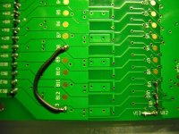
Probably the easiest way to modify the print is to use the test pads on the back side (illustrated for a 8s arrangement). This way no component has to be removed:
  • the pads V13, V12, ... do connect to the OZ BAT pin 13, 12, ... thus bridging V13-V12-V11-V10-V9 shortens the capacitors CF13...CF9 and bridges OZ inputs BAT13 ... BAT9
  • the pads B13, B12, ... do connect to the BC pin 13, 12, ... thus bridging B13 and B8 shortens the bleeding circuits BC9...BC13
SmartBMS_mod1.jpg
 
Hi,

I've just connected it and played a little bit with the parameters !
I worked a little bit on the electronics board which is very similar to your: PIC24, SD card for data logging, battery gauge

The leds are standard yellow in size 1206, but the PCB size is 0603...

I have to buy some connectors to connect the BMS to my batteries and I will can start real tests but it will take a long time...
I'm loaded at 300% at my job and it will continue like this all the summer :cry:
 
gip_mad said:
Here's the datasheet. Password is wizardofoz
Have fun! 8)

Hi. Rewgards from Spain.

I found this interesting forum in google. I have a Epedal Primo ebike, and I am trying to connect my BMS (based on a OZ890 chip) whith a PC to change some characteristics of the regulation (short current and time) and monitor my batterys. This is my batterys-BMS pack:


As you can see there is a I2C port. I found a cheap I2C/USB interface, Arduino model (12,95 USD), and I think it can works OK whith cowboy program. When I receive the interface i will share the experience whith all of you.

Anyway I need your help, no way to found the OZ890 datasheet. When I download the attached file from grip_mad, the file seems corrup, of course using the password. Can anyone send me this datasheet (uncompressed)?.

Thanks for sharing.

EDIT: File received, and works OK.
 
Anyway I need your help, no way to found the OZ890 datasheet. When I download the attached file from grip_mad, the file seems corrup, of course using the password. Can anyone send me this datasheet (uncompressed)?.
Anyone, please send to me this datasheet (ds_uns.pdf). My email - al*******@gmail.com. Thank you
..... File has already received. thank you very much.
 
I2C/USB interface, Arduino model (12,95 USD) received, but it does not work, command level not compatible whith O2 interface.

Anyway, I am trying to implement an arduino system (easy programming microprocessor system) whith I2C to communicate whith OZ890, and read and edit registers.

Notices ASAP.
 
Hi, found this thread by accident, thought will post here about my issue with this BMS and somebody might have a solution for me. I have all hooked up and it looks like BMS isnt working. When i connect + to BMS, charger kicks in for few seconds and goes out and after about 10 seconds dose same and stays off. When i hold + wire to bms between my hands (being bms in one hand, battery in the other) it starts working ok. It is some kind of mystery.
I am using it on a123 20Ah cells in 12s configuration with 5a charger. All cells range from 3.3 to 3.36 volts. Any input would be welcome.
Here are
[youtube]B0PJC5MexUw[/youtube]

-

[youtube]dSI0PDfBsNc[/youtube]
 
Hi all!
I do cascading 2 SmartBMS. Charge and discharge switches allow you to turn it on 100V. I replaced two of the transistor in the circuit current shunt 100 volt. Conclusion SCRL chip zener protected at 58B. in the chain of the legs of the resistor R31 replaced with a face value of 2k 30k. EFETC connected to the output optocoupler, the leg is configured to turn off the charge.
Here's my video.[youtube]p9uhOVPhUm4[/youtube][/quote]
Thanks to a colleague Mevial ​​http://electrotransport.ru site for the monitoring program, the configurator and advice.
 
great to see new faces in the attempt to master the OZ890 (which still is my preferred BMS chip) and the SmartBMS (which still is the best value for money). I would like to understand a bit better what you did, my russian is a bit rusty :wink:
us__007 said:
I do cascading 2 SmartBMS. Charge and discharge switches allow you to turn it on 100V. I replaced two of the transistor in the circuit current shunt 100 volt.
you replaced the FET on the high side SmartBMS with resistors?
us__007 said:
Conclusion SCRL chip zener protected at 58B. in the chain of the legs of the resistor R31 replaced with a face value of 2k 30k.
please explain further
us__007 said:
EFETC connected to the output optocoupler, the leg is configured to turn off the charge.
you followed the AN#16 from O2Micro? 'EFETC-Out' on high side SmartBMS > optocoupler > 'EFETC-In' on the low side SmartBMS ?
us__007 said:
Thanks to a colleague Mevial ​​http://electrotransport.ru site for the monitoring program, the configurator and advice.
looks like an interresting and busy site - what about this 'monitoring configurator' program - is it made for the OZ?
r
 
Back
Top