RUST: DIY Hub Motor Repair & Restoration

Damn... you said it KF. Too bad english speaking folks usually don't do the hubmotor design - well, at least what is copied and ends up being the factory's recipe anyway :)

I always wondered how you were so sharp with this sort of thing.. 30 years as an engineer.. ok, it's all coming together now.

Still glued to this thread.. can't wait to see your results. Maybe then i'll stop being such a wimp and ride my hub motors in the rain.
 
dave, KF is an engineer's engineer. i kid you not, he was so confident in his design he got on the road and arrived here without even bringing along a voltmeter. he carried his wiring diagram on a sheet of paper in his tool kit.

we dissassembled then reassembled his bike in my driveway and we added internal stays to keep his liner off the rear wheel, and he fixed the brake switch, i cut off the extra length of aluminum bar sticking outa his charging rig so it would fit more easily in the bag, and just like that he took off and drove across oregon in like no time, got there in the afternoon way over in bend. a honda wagon fanatic friend of mine saw him going up hwy 26 to mt hood while he was driving back from repairing an expresso machine out there.

great thread, i think i will spray the inside of ever motor i open from now on, especially to seal the hall sensor legs from shorting with moisture.
 
Kingfish said:
miro13car said:
You want dealers to demand quality from China manufacturers?
You got to be kidding.
The first responds from manufactureres would be that they are going to increase prices.
No way you can have all your suggested improvements and still $200 USA dealer price on even medium size hub motor, even manuactured in China.
Anyway almost sure those improvements cannot be done in existing plants, no machinery
Name of the game in China brand manufature is - use cheapest parts and materials possible/
When I worked for the toy company many moons ago I wanted to make the batteries fit into the compartment in one direction; make the toy so that there was no +/- pole swapping. It turns out that this can be accomplished for ONE penny per unit; a single wire is all it takes. I told my boss he could take the penny out of my paycheck. Management agreed it was silly to save a penny for the trouble it caused consumers, so I got my wish. :D

Let’s evaluate the cost of my proposals:

  • Sealing the stators is like adding a coat of paint, one thick coat, or maybe two thin ones. The cost is less than a quarter dollar per unit at 10,000 units/month. Gosh, no more rust, and way-happy consumers. Was that expensive to accomplish? No – it’s easy-peasy, and I know China can do it cos we’re already getting starters and alternators from them.
  • Venting: The hub covers are cast aluminum. Mod the mold for say - $1000; it’s probably a lot less. It’s just an insert into the mold; they do it all the time. Part is now vented at the seam along the periphery. This is their design flaw: They should eat the cost.
  • Axle bearings: There are two bearings per motor. One is a sealed bearing, and the other is not: It uses a rubber seal that costs nearly as much as the bearing. Get rid of the unsealed bearing and rubber seal and replace it with a sealed marine-grade bearing. Money is saved, enough I’d wager to pay for the two fixes above.
  • Connectors: Gosh, if they use the USB Mini-B along with an APP clone connector, well – the Mini-B is pre-formed in massive counts, and all they have to do is snake the other end of the cable through the axle and mate it up with the HE sensors. Money is saved cos they don’t have to assemble the Molex connector. And money is saved cos they don’t have to add the nut/washer; they can just remain packaged in a plastic bag tossed into the box. Man – we are saving money left and right! Let’s spend that coin on upgraded phase wires; should only cost us about another quarter dollar.
  • Disc Brake interface: Once the unit is assembled, during the functional Q/C test, take 1.5mm off the flange side where the disc is going to mate so that it is FLAT and PERPENDICULAR to the axle. Not a big expense; maybe takes a dollar to do that step, maybe… They have to Q/C the motor anyway so that they know it works, at least – that’s what we do in my country. And as for making the motor compatible with American and European calipers, well we are back to the business of making product that matches our market. If they can’t swim in our pond, if they can’t cook in our kitchen, then THEY NEED TO GO HOME and think about who they are trying to sell to cos we’re not a bunch of idiots…
Or maybe we are! :p Maybe we are just that weak, stupid, and ignorant. BTW – I have some swampland in Florida I would like to sell to you. And whilst I’m at it, lemme sell you some unprotected motors that don’t exactly fit your standard, and we won’t guarantee quality either, but you are going to buy them cos it’s YOU (the general consumer) that are cheap cos you are eager to put up with it!

I’ve been an engineer for over 30 years. I’ve quit jobs if I thought the client was deceitful. I won’t make or ship shit that I wouldn’t buy. My role in this hobby is to learn. Make something work off-the-shelf. Great, now I’ve done that. Now I am paying the price for choosing these particular motors. But let’s make one thing perfectly clear: What other country is making this class of motor for bicycles? Germany? Japan? United States? Maybe in limited quantities… I struggled to find them. The practical choice came down to Crystalyte, 9C, Bionix, Golden Motor… Not a huge selection out there. :roll:

As I said earlier, I’m ready to build my own motor. The links to that study are in my sig. I only want to make two: one for the front, and one for the rear. I want to go fast! I want to be free! If it works and people like what they see, well – that could be another project. 8)

The continuing saga of the motor R&R:

  • Second coat of Rust-Mort has been applied this evening. I decided to do this outside under cover from wind and rain. It was far less stanky. I waited a bit before bringing the stators in. The change is not obvious since the remaining rust is slight.
  • Also tonight I treated the rotors for the first time. I’ll upload pictures when they dry.

One step at a time.
Thanks for the support and encouragement, KF

Seems that most motors have one problem or another. My brand new C-lyte 3540 has wire damage without even being on the bike yet so I had to pull it apart and make a cover to keep the wires from getting completely worn through in < hundred miles. What no testing anything before it is put on the market? My BMC's both had poorly machined axles as well as other problems. Looks like you are doing it right now anyway so they should last for awhile. But really it would not take much for the manufacturer to do it right in the first place.
 
it is almost funny how people buy China brand product and try to apply Western quality standarts to it when this product costs like 10% of cost of equivalent ofWestern product.
It anly seems that it can be improved so easly, really that easly?
if they have like thousands to make in a year?
you forgot there is cost to improvement.
I charge you 190 bucks only but....You improve it yourself , it is untold truth for China brand.
It is simply NOT ready to use motor,etc.
Example new ht/hs series motors from China factory.
 
I’m confused…
A starter motor/Alternator is well-made because by contract it has to pass muster of State/Fed Code. Those costs are reasonable. The DD hub motors I have been referencing are simpler than those items and yet they have the same price. One person told me that 9C hubs are produced at a rate of 40k/month; that’s one factory in China, and there are many. The cost of production is wrapped around the first five, ten units, 100, even 1000; when working out the quality and supply-line issues.

Personally, I enjoy my job when I can walk out into Production, inspect The Line, interview assemblers and managers to see how things are going… It’s the feedback that’s important: It could be just the smallest thing, maybe a radius on the corner, or if this part was threaded we could save a nut and washer. :)

Basic Engineering Principle: Spend 10% more on Engineering the product correctly, and save 120% in Support and Service. Many in upper management never get this at all: They think that by rushing the product to market, or by shaving a few cents on unit production that they are making huge profits, however the truth is that a lot more is spent in supporting and servicing flawed product, especially in Software (such as lack of proper documentation). It’s the reason why we’ve evolved into a throw-away society: Cheaper to chuck it. That is until someone else figures out that there’s a lot of rare metals being tossed into our garbage. Next thing you know, we’re digging up our own compost, off-shoring salvage to a nation with little thought on human rights where they send their children in to go and dig out the gold. :(

Second part that is costly is gaining the bad wrap: Make a good product and eventually people will find it, with opposite is true for bad. Levis, Coke (Coca-Cola) Kleenex, Google: Good products, so reputable that it became part of language. Bad products we will never forget: Corvair, Betamax, New Coke, Windows ME. Speaking of Microsoft, product development of the last fifteen years often appears like they will create five independent teams, seed them with a concept and delivery date, then step back and watch them duke it out. The winner is often not the best engineered solution, but the one that has the best political chops. Is the cost of that development MY FAULT? That is the American Brand of today fostered by flawed Corporate Management. The problem is that these people have never been in War, and I’m not talking Corporate War.

In real honest to goodness War, where people’s lives are at stake, where the Nation depends upon Service and Quality instead of Power and Profit, when Resources are rare, where the Supply Chain is at risk of collapse, there is zero room for error. A company that makes shitty product doesn’t survive for long; it’s nationalized. Here’s a great story that was born out of WWII: Geometric dimensioning and tolerancing. 8)

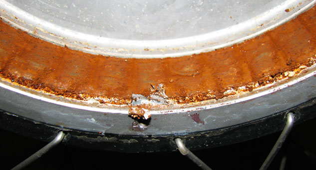
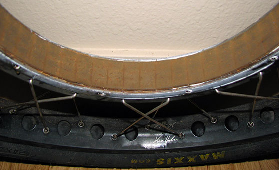
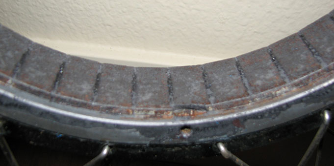
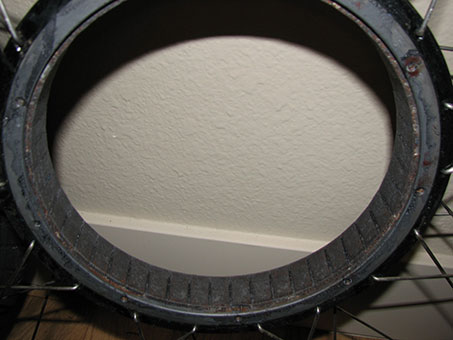
Yes, this seems like a dry boring spec, but to me – it’s the dream come true! This is how we won the last Great War: Disparate allied countries making usable products that fit across the seas by defining a common international standard and adhering to it. We consumers appear to be willing to ignore the standard for cheap product. Actually – allow me to correct myself: I have little tolerance for shitty product that is deceptively packaged, where suppliers attempt to train us that shitty product is acceptable, and that it’s OUR FAULT the components rust out. What a total scam! :eek:

When I buy clothes, I look at the label: Where is it made? I am not anti-PRC; I am against being forced-fed to accept corruption in Government, in Management, and in the supply chain. You don’t buy moldy fruit and vegetables at your local supermarket, and the employees of the supermarket certainly will not tell you that moldy fruit and vegetables are good for you, and that it’s your fault for not accepting them – do they? An impoverished country may not have that choice – but WE, as free peoples, DO have a choice!

The cost of making something correct isn’t that much at all when you step back and take in the whole enchilada and imagine: What is the cost of supporting flawed product? What is the cost of my safety if this unit fails at a critical time of need? Is my Life worth it, to continue to support entities that do not serve us properly, that overtly deceive us?

My first two motors won’t be cheap. But then – I expect that. The cost of creating those units, the special tooling and programming of the CNC machines is expensive – but then it’s only paid once. All that’s left is material, assembly time, and packaging scaled directly to quantity discount with ample time to avoid rush charges. Economy of Scale.

I just like creating fun, and watching others enjoy my toys! That’s what I have time for… :wink:
My inner-child is never stilled for long, KF
 
Status – January 11th

It’s been hell-busy at work and I haven’t been able to take off for a long lunch to discuss the hub cover repairs with the machinist… but soon, very soon. In truth, I’ve been sitting on my arse cos it’s colder than my x-mother-in-laws’ love out thar. However, I did promise some pictures a while back – so here they are. :)

These are the rotors after one Rust-Mort treatment.

P1-1111FH03.jpg

Original rusty buggers

P1-1112.RH04.jpg

After the Vinegar treatment

P1-1211.FH01.jpg

FH: After one Rust-Mort treatment

P1-1211.FH02.jpg

FH: full view.

P1-1211.RH03.jpg

RH: It’s pretty much the same shape; incrementally better and needing another dose.

There’s still a long ways to go. The stators are not that much improved since the last time; you’d hardly notice between the two coats if I took a picture of it, so I’ll wait till the end before I go and varnish it all.

Rotors: The part that worries me a little is how the residue has migrated between the magnets; I should probably get a toothpick or hard plastic bit in there and try to scrap that out. Rotors could definitely take one more treatment. Stators need one more fer sure, and that might be it; nearly done. :)

Cheers, KF
 
We’ve had snow for a week. Yesterday it began to melt; there’s still a lot on the ground in the form of wet mashed-potatoes. Today the weatherman says it got to 42°F. That’s good enough for me. :D

I spent the last 90 minutes outside cleaning the scale off using a stainless steel snipped spoke-end that had a nice sharp edge to it cos it’s not attracted to the magnets. Did a reasonable job. Pooped out though from scrubbing away removing black scale and acid deposits. Hands were cold and stiff and I thought about calling it a day, but – I really what to finish this, so I applied yet another coat to both rotors and stators. This might be the last round; it’s looking very good with only a couple of spots of rusty patina left.

Tapped off the excess out in the drive; the melt will wash it away. I think it’s plenty aerated; the acid out-gasses most went reacting, and that part is done. Waited about 15 minutes and brought it in whilst still a bit wet for it to finish up and dry. I’ve had the heater going full bore all week, so the humidity is very low; should dry out in no time. But I have to say: Even at 42°F, this Rust-Mort stuff reacts right away; you can see the change in the metal within 30 seconds.

When this is settled (fingers-crossed starting tomorrow) and I am convinced it doesn’t need another coat, the next steps will be:
  • Clean off the last of the residue and wash the treated parts.
  • Upgrade the wiring on the Rear Hub.
  • Varnish both rotors and stators (needs a warmer day).
  • Prep the covers for the machinist, and have him replace the bearings and seals, and vent the sides.
  • Reassemble.
  • Pray it works.

Working with that acid, my hands have never been so clean! :shock: :)
~KF
 
Superbowl Sunday
Waiting around for the game to start, I became ambitious and decided to wash the residue from the stators; it was caked on pretty good so I gave it a ½ hour soak in a tub full of warm water. The crust did not want to loosen up with the toothbrush, but my fingernail did the try. They are now drying out. I am looking for any new rust to form as a test to see if the Rust-Mort treatment did what it advertised.

The hub covers' brake-side already had the discs removed so there was no extra work before cleaning. Here I used a bottle of white vinegar that I keep around for laundry and stainless. Just a small splash into the bell of each cover and I went at it with the toothbrush consuming the rusty residue and attacking the surface where the bearings are inserted. The vinegar did a very good job of removing those crusty surfaces. Rinse & repeat & rinse: They are as clean as coldwater can get them.

Reminds me of a joke:
  • Grown son off to visit his Dad who’s really getting on in his years. Dad makes dinner. Son is putting the plates on the table. “Dad, these plates don’t look very clean.” :(

    “They’re as clean as coldwater can get them!” the old man replies.

    Son is placing flatware down and notices debris still clinging… he wipes them down with a towel and says “Dad, this silverware still has crusty bits on it.” :?

    Again – “There as clean as coldwater can get them!” his Dad grumbles.

    Food is on the table and they eat. With dinner finished, his son says “Here Dad, let me do the dishes…” :)

    But the old man replies, “Oh no, I’ve got them.” He whistles twice sweetly “Here Coldwater, come on boy…” and in comes the happy dog all tail-wagging…

    Moral of the story: If someone says it’s as clean as cold water can get them, go back and wash’m again! :shock:

I plan to do one final clean & Rust-Mort treatment to the hub covers once I get them back from the Machinist. :wink:

The rotors do need washing too, but that can wait a bit longer. I misread the Rust-Mort directions: It essentially guides the user to remove the majority of the debris with a wire brush, though leave some residue behind for the chemical to bind with. This creates the “coating”. Applying 3-4 layers thinly builds up the protection. Then wait 24 hours to completely dry, and then apply the Bondo or whatever body filler and priming. Evidently the coating is not that long-lived before it can become compromised. I can see what they are talking about with the rotors: There’s a white precipitate that has formed where the acid has continued to do its’ work. The stators weren’t too bad and I was catching it every time by scraping it off before the next treatment. The reality is that if it hand not been so dang cold outside this job would have long been completed. Anyway – take it from me, go with all speed to complete the steps; it should be a warm-weather task that goes quickly rather than slow and dodgy in the winter. :roll:

OK, I’m ready for the big game, so…
Rootin’ for no one in particular, KF
 
Day after Valentine’s
Last week I took the hub covers down to a motorcycle shop a few blocks away from my client; they said it would be no problem to the work:

  • Pull out the old seals
  • Replace the rusty bearings
  • And ventilate the covers with 3 holes equidistant at 1/8th inch diameter.
Took two days, and about $110 for labor after tax. I spaced and only had one set of seals, so the second set was ordered Monday morning before dawn on the west coast to a company on the east coast. Service this time was pdq: The package arrived this afternoon! Here’s the pic:

P1-HubRustR&R0.jpg


The black bearings are a little stiff; smooth but with resistance. Not terribly worried. The brick-red bearings are silky smooth and rotate freely. The seals pressed in without much trouble; I didn’t have a mallet though was able to tap them in using the plastic-end of the screwdriver and a hammer. Good to go.

One last slap of Rust-Mort on the steel parts of the covers and that will be that. Stators need one slap as well, but before I can do that, I need to upgrade the phase wiring on the rear hub.

One small step for man, KF
 
Keep up the good word i hope everything turn up fine or even better when you put everything back together looking forward to seeing everything completed ! Almost makes me want to open up my motor that i have had for three years in all types weather and never opened it up :)
 
Rust & Restoration – The Saga Continues

Greetings ye kindred ebike wayfarers. It has been a long cold lonely winter. Then spring came and went. Now, we have the Seattle-equivalent of summer, which just means the rains are warmer than in the deep darkness of winter. There’s a big orange glowy thing in the sky that scares me. Some call it “the son”, but I don’t what son they mean. Anyways, it rarely rears its’ head. Now back to rain…

Confession time:
Last November when all this shite went down, I somehow pulled tendons or ligaments in my left knee at home. Might have bumped it on the coffee table... it's a mystery, however is was really super painful and felt like I had been hit with a crowbar by some hired thug of an embittered ice skater. Anyways, this event happened around mid-November, hobblingly about though I could still barely ride the ebike. When the second motor rusting out, it was pure suffering trying to do this work on my knees. For therapy, I had the leg raised most of the time, eating Ibuprofen like popcorn, and did a lot of walking. It wasn’t getting any better. Weeks, then months went by with improvement, then relapse. Finally saw a sports-doctor last month and he just put me on stronger pain meds and said to bare through it cos there’s no meniscus damage, and gave it a name: Quadriceps tendonitis. The situation has improved; I've been walking 12 miles or more/week, the knee is stronger and less painful. I’m back at the repairs for the past couple of weeks.

Status as of yesterday:
Repairs were idled but I finally got on the stick and started wrapping things up. The weather since July 4th had become noticeably warmer and stayed in the mid-70s for days since. I been waiting for this so I could varnish the parts.

Since sitting for so long, both stators picked up a tiny bit more oxidation; I hate to say rust – though it was discoloration from the humidity. Bought a small wire wheel and cleaned them all up bright and spiffy.

P1-1207.FH01.jpg

Front Stator

P1-1207.RH01.jpg

Rear Stator - taped and ready to go. Used Liquid Tape to seal the HE solder joints at the lower-right.

Parallel to all this, I took the hub covers over to a local mechanic that does R&R on ICE; I wagered correctly that he had a bead-blaster. Wasn’t having much fun using the wire wheel on the covers to remove the build-up, but for $50 he kindly cleaned them all up real purdy-like. Picked them up on Friday the 13th. Gave the ventilation holes a slight debur/chamfer and wiped them down with alcohol.

The rotors were also cleaned-up one last time and wiped down. Then spent 4 days varnishing using the same stuff as DocBass except I liked the green color better – being EV and all. Or it could have been that was the green stuff was the automotive/industrial strength… whatever. Doesn’t matter now; I’ve got the goods in hand and it worked pretty well. With varnish, spray on light layers and allow to cure, otherwise it stays tacky for a long time and is a pain to handle the parts cos yer off to the sink trying to scrub it off yer hands. PitA.

P1-1207.01.jpg

Finished Results

Closeup of Rear. This stator got the phase wire upgrade this time around. The Front already had the mod applied last year. During the 2011 road trip, the rear phase wires did become very hot. I pulled Ethernet sans outer sheath (24-AWG x 8 ) + Phase Wire (12-AWG x 3 ) through the axle which only had the stator-side exit hole cleaned out nice and smooth. It took about an hour, maybe two of cussing and swearing like a sailor to work the wires through using Teflon Grease for lube.

P1-1207.RH03.jpg


Here’s a close-up of the varnished rotor. Compare this to the rusty original.

P1-1111FH03.jpg

Was :x

P1-1207.RH02.jpg

Is now :D


The Stator-side exit hole was covered over using Liquid Tape. It took several coats. When dried, if feels a little waxy like Polyethylene, but is actually quite durable. The Liquid Tape is really best for coating statically affixed connections; do not use it on wire that flexes otherwise it will crack.

P1-1207.FH02.jpg


The bead-blast really did a remarkable job on these hub covers! Front & Rear shown. So much better-looking than that ugly scale.

P1-1207.RH04.jpg


Halls on the Front Stator. The Rust-Mort really cleaned off the corrosion well for varnishing.

P1-1207.FH03.jpg


P1-1207.FH04.jpg

Top view

Another compare/contrast: On the left is an original never-been-used stator next to the varnished unit.

P1-1207.02.jpg


Everything is set for assembly. I can't begin to tell you how much time and money I've spent on this repair, but at least I can see a light at the end of the tunnel. More in a bit.
~KF
 
Extremely cool. Can't wait to see how it goes.
 
T'anx Nep :)

Small Issues:
The FH has been reassembled and is on the ebike ready for a freewheel test. Without power, it spins with little effort and feels solid. I have to put together a battery pack before proceeding; briefly... the battery harness and batts were stripped for evaluation (another small project altogether).

So far so good, except that when I reassembled the RH, there was some minor rubbing. Took it apart again and the HE wires were wearing away. How could this be? I tried to bind it closer, moosh it down better, reassembled & tested – slightly better but still rubs. Anger set in and I was a bit aggressive and tore a HE wire off the sensor. Now it’s buggered good. :oops: I tried to solder it back but the solder won’t take to the wire. WTF? :evil: I finally gave up and chiseled out the HE sensors and ordered replacements yesterday from Digikey – Honeywell SS41, Qty-10… in case the FH has issues too. Anyways, those items will be here in a few days.

I also ordered the EC5 connectors from HK on July 12th; checked the status and they’re in New York as of the 16th. Hopefully everything will come together soon: New battery harness sans pesky APP, refurbished and rust-resistant hubs, winning lotto ticket… er… um, well 2 out of 3 ain’t bad. :wink:

Related threads:
soldering hall effect sensors
Liquid Tape or Plastic Dip instead of Heat Shrink?

Waiting on the postman, KF
 
mouser has much better prices for the hall sensors. i paid 65 cents each for a 50 ct lot as i recall.

were they hall sensors hitting the rib on the inside of the cover? how did they get so far out? you did not remove them for this cleaning from what i recall. maybe the liquid rubber is really thick and hits the rib?
 
Mouser: Understood. Next time perhaps :)

The HE sensors are buried below the circumference of the Electric Steel, and the Liquid Tape was not the problem; the heat shrink of the original construction was rubbing against the hub cover ribs where the signal wires arc over the winds. Just spinning it by hand – one could feel it rubbing pretty well, and it was unacceptable.

The only reason they could have moved away was during the rehabilitation; maybe I didn’t synch them down tight enough cos I sure thought they were quite snug. Then again maybe the dufas that engineered the hub covers for disc conversion didn’t allow for enough clearance… one can only speculate why 1 or 2 mm could make such a drastic difference. My plan could include using a 1.5 mm bronze shim to move the stator away from the cover on that side. There’s lots of room under the opposite cover so I don’t understand why the redesign was so entirely flunky. Frustrating. :x

I also considered that the hub covers are mixed up though I can’t see how that could be: It’s the only threaded (freewheel) side I have, and the wiring has to exit on the other end. Again – frustrating.

P1-1207.RH05.jpg

Color of each phase denoted above empty HE slot.

Now that the sensors are removed, it left the winds exposed and I was able to lightly tamp them down about 1 mm more which combined with the bronze shim should improve the odds of success. From the top yellow line, you can see that I’ve mooshed the phase wires down a bit more than the average winding height. The second shorter yellow line is where the bearing will sit against the stator axle: Not a whole heck of a lot of room to work with.

P1-1207.RH06.jpg

Windings mooshed down a bit to allow for clearance of the HE signal wires.

You know – looking at this silly layout, I can see a perfect application for a flexible Kapton-backed flat-wire harness. So simple a child could put it together!

The adventure continues. KF
 
GOOD NEWS!
Hooked up battery power to the system in a kinda jury-rigged manner and tested the FH on both F & R controllers: Wheel spins without issues – and seems more quiet & happy as a clam to do so. I am relieved; at least I am batting 1 out of 2 so far.

ADDENDUM: Added FH assembly below... not much to see, but at least I did take pics :)

P1-1207.FH05.jpg

Left side attached first, then dropped in the stator next. At this time I didn't bother with sealing the covers before knowing if it would pass the freewheel/smoke test.

The ray of hope & optimism just became three notches brighter :D
~KF
 
Been a while since I posted on this thread. Finally tested both motors together today.
  • The RH has the phase wire upgrade from whatever- it-was thin wire to 12-AWG.
  • The FH started up in forward rotation with no problems, except one which I’ll describe in a minute.
  • The RH took me nearly an hour to diagnose. I think this is a Lyen-specific controller issue and ended up having to swap BLU & GRN wires on both the Phase and the Halls to get the motor to rotate forward. Anyways – it’s done.
Very odd artifact: Both motors appear to operate at ½ speed. I tried the front controller on both and it’s exactly the same; both motors run at ½ speed at WOT. The 3-Way has no effect. Both motors top out at about 21-24 mph. Possible reasons could be:
  • Controllers lost their programming/returned to factor default values from being removed from the battery pack for months.
  • Both motors are damaged from Rust, and I’m buggered.
The FH sounds good and quiet when it runs, however the RH has an alignment problem with the frame because it's just a quick test, and it could be that I’ve somehow reversed the rotor so the dishing is backwards. For some reason I didn’t think the RH had dishing, but I’ll review older images of the ebike to see if I have the rotor on backwards. Anyways – it rubs slightly against the frame so I can’t tell if there are other issues.

That’s the status for today. The new battery harness is in place, I just need to finish mounting the disc brake rotor and hardware onto each motor, and the Freewheel on the RH, should be good for a ride.

ADDENDUM: Crap! Both rotors are on backwards. Oh well... the hub covers are not sealed yet. The FH looks centered; I'll just swap the RH for now.

Somewhat optimistic, KF
 
Reversed the rotor on the RH and gained 5-6mm of tire clearance; good to go. However now there is some very slight rubbing inside the motor. Mounted it anyway just to get an idea, and it runs forward kinda rough like a throaty rumble. It could be that the phase and Halls are off, but given that the FH wiring has not changed and it too runs at half speed, I am not certain this repair went well.

From other reading, the motor doesn't start well, so it could be that I still do not have the wiring correct which is odd cos I was quite meticulous in note taking during disassembly.

Here's what I have so far:
RH had the Halls replaced; I took precise notes and the color codes for the Halls were as indicated below:

P1-1207.RH05.jpg


If we presume Blue = A1, then Yel = B1 and Grn = C1. (I don't know if this is true, however - I have a 9C disassembled in mint condition and the Halls color code is exactly the same.) On the flip-side where the Phase wires depart the stator, the wire colors are from Left-to-Right: Blue, Yellow, Green. I have a 9C FH motor mounted on a rim, though never driven on the road; it's my debug stock motor, and I use it to test my controllers after moding. The wiring on it (except for the USB connection) is exactly the same for the Phase: They use Yellow, Blue, Green in that order, which makes me think the timing is B A C.

After much testing, I went through and resoldered the HE connector to match exactly color for color SA, SB, SC and tested with a multimeter. The results I get back are:
  • Nothing, locked, or studdering,
  • wicked fast forward to 72 mph with zilch for torque,
  • smooth quiet running reverse to 28 mph,
  • and rough forward to 25 mph, no matter how I switch the hall signals around.
Just to be clear, if the Controller is A (Y), B (G-Lyen/B-EBikes), C (B-Lyen/G-EBikes), and I have the phase wires from the motor set to Y, B, G - I get nothing, but if I set them to B, Y, G... I get rough forward rotation up to 25 mph. Both controllers behave nearly identically (slightly different wattage limits, otherwise the same).

I'm beat for tonight and this testing has given me a stress headache. Tomorrow I'll swap out the motor and use the stock OEM 9C to see what's up and if the controllers are performing correctly. All I can think of at this point is that I'll need to open up the motor again and check the wiring relative to the stock 9C and make them identical (even though I thought I did this already). :oops:

FWIW - hanging onto the bike whilst that rear motor spun up to 72 mph was something else! My hand grew numb from gribbing the frame 8)

bushed, KF
 
Greetings –
I took the day off yesterday; just needed a break and clear my mind. Now fresh and back at it, it appears that the Worm has turned!

I tested both controllers with the Test Hub: A 9C FH 2807 no-disc, and completely stock, except for the Mavic rim; doesn’t even have a tire on it, so it’s lighter for swapping on and off the frame. With the Test Hub mounted to the front fork:
  • Front Controller - wheel spins smoothly to 22-23 mph in Reverse.
  • Rear Controller - wheel spins smoothly up to 21 mph in Reverse.
What the heck? Well – all I can think of is that maybe 25 mph roughly forward isn’t so bad now. Sure would like to get that smooth running 28 mph in Reverse to go that way in Forward; that would be a neat feat! :)

Went through my photos of the motors just before and during rework and confirmed that I managed the wiring correctly inside the motors for both HE and Phase coloring. In addition, I was able to confirm that the color codes for FH and RH are different, and therefore must continue to be expressed that way at the connectors.
  • The FH, A->C is Y G B.
  • The RH A->C is B Y G.
  • The Controllers A->C are: Ebikes Y B G/Lyen Y G B
  • The Controller-side of the Phase Connector is expressed as A-B-C for both controllers, and using the Ebikes coloring convention of Y B G.

The Pictures tell the truth...

P1-1111FH04.jpg

FH Phase = Y G B.

P1-1111FH07.jpg

FH HE wires are also Y G B.

P1-1111FH01.jpg

FH at the connector is Y B G (A C B); I don't know what the Halls are without tearing into it.

P1-1209.RH01.jpg

RH HE wires = B Y G. What a mess...

P1-1209.RH02.jpg

RH (nice and spiffy before varnish) Phase = B Y G (it's a little deceptive as the Yellow wire snakes back in place).

From careful reading on ES threads, I was able to determine that the Reverse I was seeing for the RH was absolutely correct… for a FH which has the wires exiting from the motor’s right side. Furthermore, I deduced that if I swapped B & C Halls on the RH motor wiring, this would enable reverse direction for the RH. Based on that, out of 6 combinations of phase wiring, the one that worked best was:

  • Controller -> Motor: A-A, C-C, B-B, with Halls A-A, B-C, C-B.
This produced a freewheel spin of 41.1 mph using 275 W @ 60.7V or 4.5A. Note however that I have not well calibrated the CA. The RH still has a bit of rubbing inside but I know that is not the Halls. However with each test of the motor, it began to sound better and less throaty, as well as spin faster. The starting Torque at 41 mph is kinda crappy. The new question becomes: Why is the FH so slow?

Next, I connected the fixed RH to the Front Controller, and this time it spun forwards quietly at 28 mph using only 60W of power and had awesome runaway pony-kickin' torque. Perhaps the previous 41 mph is not so great after all. I must presume that whatever I have done to the Front Controller, I should do for the Rear, yes?

Getting closer & feelin' better about it, KF :)
 
Greetings –

Time for an update:
I accidentally blew up my RH controller during testing. This was replaced a couple of weeks ago. As it turned out, I blew out the Halls Throttle as well, so I was doubly delayed waiting for parts. The new RH controller is the 12 FET 4110 MOSFET Extreme Modder Controller LYEN Edition MII (EBS312). This was successfully flashed this morning and I proceeded to continue resolving the Phase/Halls/Controller wiring.

A note about the wiring…
The first thing I did was chuck all common logic and instead relied on the Phase ID. As with the previous post, we can see that the entire system is hamstrung with inconsistent color coding from the get-go, and I mean direct from the manufacturer it’s just FUBAR. So without much ado, let’s tackle the problem directly.

I have resolved the Rear Hub wiring correctly for forwards and reverse. The latter came before the former, but just as well cos it will help me when I get to the FH redo. Regardless of color, this is the proper wiring depending on which direction you want to go:

Rear Hub, Phase and Halls exit on the Left/Port side of the bike/9C wheel. The opposite is true for the FH, exiting on the Right/Starboard side.
  • We desire FORWARDS direction on the RH.
  • Halls to Controller must be wired as A-A, C-B, & B-C.*
  • Motor to Controller must be match-wired as A-A, C-B, & B-C.*
  • This arrangement produced a quiet very torquey fast freewheel spin up to 40.5 mph; it would be faster except my pack is running a bit low after sitting idle for weeks.
*Caveat: You can swap any two of the three Phase/Halls IDs so long as they are matched (Credit: Dogman).

REVERSE direction can be had with the following configuration:
  • Halls to Controller must be wired as A-A, B-B, & C-C.
  • Motor to Controller are wired slightly different as B-A, C-B, & A-C.
  • This arrangement produced a quiet very torquey fast freewheel spin up to 40.5 mph in reverse!
The color mapping was accomplished in Excel.
  • The RH is mapped as: Motor/Halls: A=Blue, B=Yel, C= Green.
  • The FH is mapped as: A=Yel, B= Green, C= Blue.
  • Lyen Controller: A=Yel, B= Green, C= Blue.
The biggest pickle in keeping this coding straight was with the Halls because I used Ethernet cable which has it’s own color scheme to extend them out from the motor, and then I transitioned to the USB-Mini B connector which is also unique. That whole sequence – regardless of Phase ID, respects the original Halls color, and it goes like this:
  • Halls -> Ethernet
    Yel-> Brown
    Blue -> Blue
    Green -> Green
The transition from Ethernet colors to USB Mini-B is a bit more tricky cos the doggoned Phase colors are different between hubs, so I match that back to the Controller as:
  • USB -> Controller
  • Yel -> Yel
  • Green -> Green
  • White -> Blue
Got all that? :? :wink: This is consistent regardless of which controller.

So for the RH, Ethernet to USB is:
  • Blue -> Yel
  • Brown -> Green
  • Green -> White
Whereas FH I expect will be:
  • Brown -> Yel
  • Green -> Green
  • Blue -> White
RH Phase wiring by color from Motor to Controller is:
  • Blue -> Yel
  • Green -> Green
  • Yel -> Blue
Lastly, I expect the FH Phase wiring from Motor to Controller to be:
  • Green -> Yel
  • Blue -> Green
  • Yel -> Blue
I’ll know more (hopefully today) when I remount the FH to the frame. :)

- - -
ADDENDUM: @3:55 PM... I have the FH remounted and the Halls were already in the correct direction, however the color key did not match and when I tried the guesstamate phase wiring I got the throaty slow reverse spin - which meant that I was off by one. Re-evaluated and FH Motor to Controller is:
  • Yel -> Yel
  • Green -> Green
  • Blue -> Blue
...and spins up nice and quiet to about 38 mph (which is fine cos that controller is derated by 20% to keep the FH from spinning out at Start). Restating, Motor to Controller are presumed to be wired as A-A, B-B, & C-C. From this I deduce that Halls to Controller must therefore be as B-A, C-B, & A-C. I'm not going to mess with it; the motors now spin quietly forward. I'm good to go 8)
- - -

I just want to take a moment and say that it’s really really awesome to hear these motors spin up quietly and powerfully. There’s so much torque at the slight twist of the throttle and I damn near ran the bike into the wall, (actually… I did but it hit the other ebike and fell over). :roll: <sigh>

Cain’t wait to get back in the saddle! World, beware! :twisted:
Very soon now I should think. KF
 
Yesterday I was finally able to test these motors out. I believe we can conclude this thread by stating that the Test was very acceptable and that the motors performed better than expected. There’s a pesky high-pitched singing/whine in them but I am nearly certain this is due to the disc brake. Beyond that, I am really quite relieved the rework executed well. Time… and Old Man Winter will tell if the R&R holds up. If there are no more issues to report, I should like to post again on their performance in the Spring.

Many thanks to the contributors that helped me complete this project.
Adieu & safe travels, KF 8)
 
Thanks for the report. I have been watching this thread all along to see how it went.
Please do follow up to see how they handle the rain over the long run.
 
KF, I dug up this thread while searching for a review of 9C motors since I'm planning to buy the DD 500W motor @em3ev. The review on electricbike.com is great, even had an FEMM pic. I have used FEMM lightly, I wanted to model the motors in Flux2D when I got them. After reading this thread I'm considering to drilling a few holes in the flanges and paint anti-corosion the active parts. In order to mitigate debris I should probably get some SKF bearings. Have you tried a copper and iron loss computation based on the FEMM sim? You would have to make quite a few assumptions like FeSi grade and thickness and end-turn average length, but it should give an order of magnitude. With a couple of points one may extrapolate a full efficiency map (more or less accurate :mrgreen: ).

I have a suggestion about the bearings: if the rotor is in any way misaligned to the stator you'd have a low frequency loop created in the stator that would create leakage currents in the bearings. My idea would be to use silicon-nitride ball bearings to cut this loop. We have successfully tested this with train motors and (personally) with a tiny RC motor. Google bearing currents.

Cheers
 
Hi Drebikes

>> FEMM: I have created more than 200 FEMM models of various motor configurations and would have to say that I still don’t know enough to fully utilize the application. I would learn to cartwheel if it would get me better tools, though FEMM is free and others are far from that. With help I was able to model the 9D 2806 close enough to match my realities and experiences. Then I mapped that back to my custom designs and refined the model. At this point – I’m waiting for opportunity to cut metal and assemble. Plans within plans. I build a motor: Need a frame, probably need a controller to suit. Bits and pieces of ideas come together; every day is learning how to advance these concepts to fruition.

>> copper and iron loss computation: Much was assumed for the 9C and I tried various materials, but here is where I found weakness in the FEMM application to differentiate by notable margin. The reality is I am developing an ironless motor, so after a couple of weeks of tinkering with materials that I’ll never use – it was time to move on.

>> Misaligned stators: Can’t say that was an issue. Had no control if it was, and no ability to correct it unless I owned a machine shop. That said, motors I create will have to be in balance or I won’t use them. The bearings used for this R&R were commonly available on McMaster.Com or through the SKF distributorship. That said, I dig the idea of using silicon-nitride ball bearings and shall keep that in mind for the future – thank you! :) Again however that was not an option for me with the particular physicality of this project.

A good FEMM-related thread for you is: Doing the Math. Sadly the thread suffers from gross character corruption by virtue of noobs managing the ES database transfers.

- - - - - - - - -

neptronix: Hey it's been a winter and another summer! 8) The motors are holding up. At times I feel an odd vibration when cruising but it is very difficult to tell if that's road chatter or contention; I'm just starting to notice it so let's see how this plays out with more rides. The one item that concerns me more than anything is the phase wiring as it leaves the axle; there's been some abrading during the initial mounting process back onto the bike and I feared shorting, so I worked up a kluge using a zip-tie for separation and then a splooge of Liquid Tape to seal it. Not the best solution for long-term, but it's been a year - and yesterday I logged in just enough ebike miles to break into the 10k club. And let me pipe Drebikes in on this: The bearings are holding up so far; I've been consistently hitting above 45 mph on the downhills these past few weeks - and I'm still running at 86% on the controller. Definitely due for another overclocked speed run :twisted:

Pushing forwards, KF
 
I'm looking forward for the axial motor design. A few years back at another job I did some pre-sizing of electric motors for different power/torque/speed specs for hybrid applications from cars to helicopters. It worked, too for the most part. Back then I was thinking about an own-design ebike motor and I have to admit a 2-face ironless axial motor was precisely what I found to be best from a power/weight ratio. A variation has the magnets in a hallbach arangement to remove the iron completely. As I said I'm looking forward to see something like this in the wild, it always seemed to be most promising

cheers
 
Back
Top