Ultra Motor A2B hub disassembly / repair

Joined
Jun 23, 2010
Messages
73
my Ultra Motor A2B hub developed a short. Since I couldn't find any pictures of the inside of one of these I figured I would post a few.

IMAG0082.jpg


IMAG0079.jpg


IMAG0080.jpg


I'm in the process of cutting away the epoxy to free up the hall sensors so I can remove the electronics. a few more pics to come. if anyone wants to see a close-up of something specific let me know.

DC
 

Attachments

  • IMAG0080[1].jpg
    IMAG0080[1].jpg
    91.4 KB · Views: 191
  • IMAG0079[1].jpg
    IMAG0079[1].jpg
    90.1 KB · Views: 191
  • IMAG0082[1].jpg
    IMAG0082[1].jpg
    98.7 KB · Views: 191
Thank you for sharing. The motor itself doesn't look too awful. The controller looks like a thermodynamics fail, but overall not too bad looking for a commuter application.
 
Thermodynamics fail indeed but it was fun while it lasted. it's a pretty fast wind being designed for a 20" rim and all. I guess the pictures I have posted show about as far as I am going into it. the other side of the controller is just a backing plate. basically the controller pcb was placed into its donut shaped housing and sealed by pouring a hard-setting black plastic over it. not sure how I could get into it without just destroying it completely so the next step will be to tear this controller out and sort out how to wire up an external 20A or 25A Infineon Controller. any suggestions?

DC
 
i put an a2b motor on my scooter about a year ago.hope this helps http://endless-sphere.com/forums/viewtopic.php?f=10&t=20102
 
Hey, ty for that link Friedwires. very informative. not sure how I missed that post while searching around before. :oops: I was thinking of sticking with a 25A controller mainly because my BMS is rated for: Maximal Continuous Discharging Current 30A /Maximal Pulse Discharging Current 45A. but since the motor short damaged the BMS I might just replace it with a higher amp one rather than repair it. I'm running 16s Headway cells but still undecided what controller/BMS to use.

oh, in case any one was wondering, I pulled the pressed motor halves apart with a large 3 arm automotive gear puller, tapping around the flange every 1/2 turn or so with a plastic mallet to relieve the strain. I plan on pressing it back together with 3 large C clamps and some wood or w/e to protect the case.

DC
 
I have a short in my ultra motor. The same one as in the photo. What electronic parts are you replacing. I would like to do the same. It is disassembled and everything looks food visually
 
I removed the inner controller, re-wired and re-epoxied in the hall sensors and temp sensor and soldered in some 12 gauge for the power leads.

View attachment 1

I never attempted to diagnose or repair the controller because I want to run it at at least 48v and didn't much care for the slow start "feature" of the stock internal unit. I'll be lacing it into a 26" rim, running it w/ an external 25 amp infineon controller and installing it into an EVG SX frame.

banshee.jpg

this project had been mothballed over this last winter while I collected the bits I needed to complete it. I just started working on it again this last week. Ultimately this should evolve into my first lipo powered build but I finally figured I should get it all working with some batteries I have while I am deciding what voltage/AH lipo pack to put together.

Initially I'll be using a 16s 10ah lifepo4 pack I built up which fits in the battery bay and I plan on trying it out w/ another 8s pack in a pannier on the rack to test how it runs at 72v. If all goes well I should have it up and running this weekend.

DC
 
It's alive! spins up nice and smooth at 48v. my educated guess about the phase and power leads was spot on. OK, ya, I wired it myself and had a 1 in 12 chance but still, nice when it spins in the right direction on the first try. purchased a new bike over the weekend that needed some attention so I haven't finished lacing up the wheel on this one yet and I am still dinking around w/ a step-down system and a relay board so I can use the stock lighting system, throttle and switch cluster. and no, I don't know why I like to keep things looking stock. stop asking me. Banshee should be taking her maiden voyage in a day or so tho. You remember your 1st ride on 72v? for better or worse I bet I will.

still haven't tried it at 72v... working well w/ 16s lifepo4 tho

DC
 
Sorry to bump a year old thread, but i figured this would be the place to add some info.

I couldn't figure out how to open mine... i unspoked mine and tried to use a 3 prong gear/axle puller on it and part of the spoke flange chipped off from all the force.. :(

Tried the puller on the other axle and that did not work..
I figured mine was threaded on somehow, requiring a proprietary tool of some sort, since all other motors have pulled apart that way. But i was wrong.

So apparently the key here is smacking on the spoke flanges with a hammer ... hit one edge twice, hit the opposite edge twice, and so on, until the case finally separates.

And the magnets are so damn strong that you can't use the typical 'bash the axle on the ground' trick to get the stator to pop out of the magnet housing. That definitely requires the 3 prong gear/axle puller to pull off.

Anyway, i have a working stator ( the magnet ring was screwed up because a magnet came unglued ) w/controller for sale if anyone is interested.
 
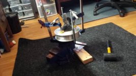
Just pulled another Ultramotor Hub apart using a large 3 arm automotive gear puller and decided to look at my old post to see if the instructions I wrote the 1st time were accurate. I noticed that I never mentioned that the hub halves are not keyed in any way so you should put a match mark across the seam to assist in lining them up for re-assembly.

And Yes, Tapping on the flange with a hammer or plastic mallet is crucial to the process. at first the puller should only be tightened up enough to apply some release pressure to the two halves. then lightly tap around the flange to relieve the pressure, making sure the gap is uniform before putting more turns on the puller. after tapping to relive the pressure, the puller should be fairly slack. tighten it up again and repeat the process. It doesn't really take very long but still, patience is the trick here. don't over crank the puller, just enough to tighten it. tap lightly around the opposite flange (i.e. the one that the puller isn't attached to) and it will come apart pretty easily.

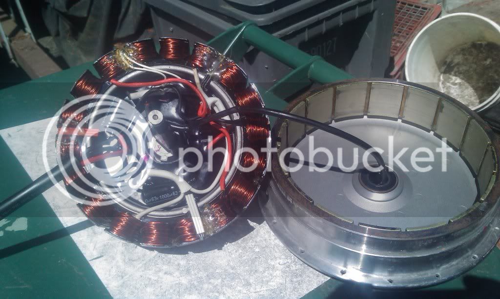
for re-assembly respect the strength of those magnets. keep your fingers out of there when lining it all up. I used 2 large C clamps with some pieces of wood to protect the case. three clamps may have worked better but I only had 2 big enough for the job. And again, patience, work slowly, make sure it is going back together uniformly. tap on the halves with a mallet and/or move the clamps around if you have to to keep the gap even as you press it back together.

I have been running the last one I re-wired at 48V (16s Lifepo4) @ 45 amps and so far it has been working great. speed on a 26" rim is 30mph.

maybe another thing to note if you find yourself with one of these motors with a dead or questionable internal controller. both the dead ones I have dealt with had developed a major short. the 1st one I had blew while I was riding it and took out my BMS when it went. this last one I bought "untested" off of Ebay and was curious if it actually worked or not. curious but not entirely foolish. I wired up some old Sealed Lead Acid batteries I had with some thin gauge wires, attached them to the power leads and marveled momentarily at the flying sparks and smoke. so, I'm just offering a bit of warning against testing one of these with a battery pack that you like and perhaps also making a case for why you should have some SLA batteries laying around your workshop even if your E-bike friends make fun of you for having them.
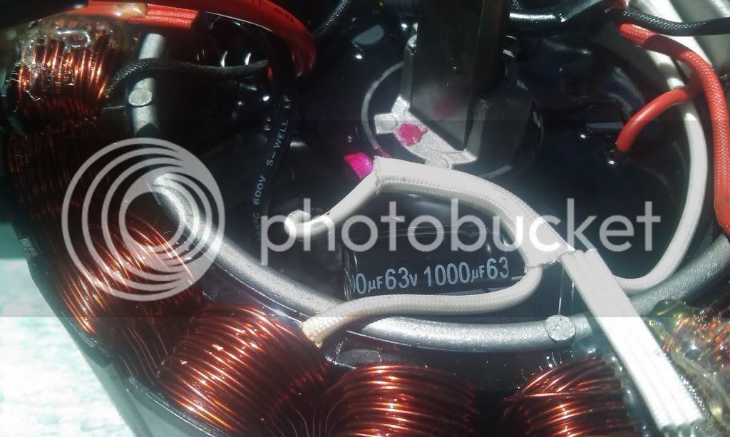
DC
 
Reviving an old thread to ask a related question on the Ultramotor "in hub" controller....
Knowing that these controllers are "soft start" and current limiting to ~25 Amps max, and seeing that it is fitted with 63 volt caps (and assume other components have similar 63v rating ?)....is there any reason this unit would not run on a 55-60 v battery ?.. Just looking for more cruising speed.
The idea is to run normally on the 36v internal "A" battery, but when up to speed on the open road, switch over to the "B" battery at 60v (15s LiPo) to boost the speed up.
I guess it might have some over voltage protection, and the extra watts ( 60v @25A= 1500 watts ) may cause a heat problem , but I believe there is a thermal cut out / protection included.
I know folk have run these at 50 ish volts, but how close to that 63 v component rating can it go before becoming a smoke generator.
Anyone tried these internal controllers at higher voltages ?
 
Bumping this to not loose it again as i'm currently working on a Metro with blown internal controller ( motor is cogging like mad ) .. i searched youtube but failed to find a video showing how it's done.. if i get motivated tomorrow i'll fire up the gopro and record myself swearing at it !

I have the rim/spokes removed ( had one broken spoke and a bunch of bent one's... will deal with that if i can manage to get it open without destroying it )

And ditto on the sparks when the controller fried, it's a dead short in there
 
a2b motor reassemble.jpg

So, got the controller gutted out, cut and resoldered the motor phase wires to 12 awg teflon with crimps..

Put new SKF bearings in there as the freewheel side bearing was gritty and had locked up, replaced both.

Tested the hall sensors, good... soldered some leads, shrink wrapped and but it all back together.

The wires exit the side that has magnets so inserting the stator and wires carefully was not really an option... i bent the wires into position best i could and let'er rip... !!!...
 

Attachments

  • a2b motor reassemble (Mobile).jpg
    a2b motor reassemble (Mobile).jpg
    27.5 KB · Views: 8,401
Nice work Yped. That excellent video will help anyone else with the same project in the future. One of the halls went out in one of these motors I rewired and not wanting to unspoke/respoke the whole wheel i just swapped the controller to a sensor-less unit so maybe i would recommend replacing all the halls when you are in there but i didn't so meh w/e. One thing i think we may not have mentioned in this thread is the temp sensor in these motors. I ran wires out to utilize them on all three of the ones i rewired but have yet to connect them to any gauge. from my experience these motors can handle 45 amps at 48 volts with out any problems so temp sensing seemed unnecessary. these seem like pretty good motors once you get that destined to fail internal controller out of them. oh, and just for the record, could you share info and a link to where you purchased the the bearing you replaced? it would be useful to have here. I probably mentioned it before in a previous post but i have been lacing these into 26" rims and they run at 30.5 mph with 16s Lifepo4. anyways, cool vid Yped. nice work
 
I guess everyone's mileage varies , as they say...but my experience with that motor temp sensor is that is will cut out on a standard set up after only 10-15 mins of moderate hill work ! And the outside of the motor hardly feels warm !
So that is 36 volts and ~~ 15 amps. And takes hours before it resets . :x
It's a real pain if you live in a hilly area.
 
A short follow up to the above...
The only A2b bike with a controller external to the motor that I can find is the "Kuo" folder..which appears to use a totally different motor.
I have owned/inspected several different A2B models and ages, including the "Metro", "Hybrid", "Obree", "Velociti", "Galvani", etc etc, but they all have the integrated motor controller of various power specs. Some look different , but still have the integrated system.
...Easily identified by ther only being 2 large power wires to the motor (+ 5 signal wires for the speed control/ Pedalec.)
..SO, anybody have any other information, or can we conclude that All A2B bikes (other tha Kuo) still have their controllers integrated inside the motor ?
 
Quick update to an old thread in case anybody stumbles upon it like myself. There's 2 and a half generations of bikes and motors that came from a2b. Easiest way to determine which motor you have is as easy as pie once you know what to look for. Internal controllers engines will always have to large wires for current carrying to the controller. The controllerless version has three for sending phase current to the hub. The new version also has 6 small wires to carry 3 hall signals, temp, +5v, and ground. Old version had 4 to carry signals to the controller. Most new versions have a "master plug" integrating all nine wires into a single jacketed cable that runs to the rear. Old version generally had the power cables and signal cables in two different jackets. Hope this helps anyone looking to restore, fix, or rebuild their ultra motor engines. Feel free to PM for anything related to these motors
 
Hi, I have an A2B hybrid 26" and I was wondering if it is possible to replace the LCD display for another one? Mine got wet and blown. Fried one of the connectors and I will need to replace it. any Ideas how to go about it and would a universal lcd like the kt-lcd8h work?
 
I'm new motor rebuild. I have an a2b ebike. I bought it with the motor not working. The previous owner drove it with a 48v battery. It worked for a few months then quit. I have the hub apart. I need some help for my next steps. I want to use an external controller with the 48v battery . Do I need the hall sensors if so how do they connect to the new controller. What would be the best controller? Thanks
 
Back
Top