:oops: Fixed EB 218 Over volted now no 5volt

Ok, thanks guys.. I must get some glasses...seriously.. I have never had glasses..always had exceptional vision..but lately..reading small stuff in low light is becoming a bit of a strain.
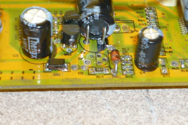
After I posted, i did actually spot that zener, ...honest

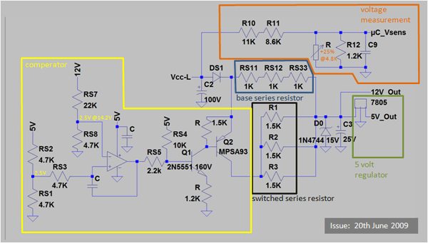
Hugues, what you say makes sense, and there is 20mm hole drilled through the board under those big resistors..to aid air flow around them maybe?. But I reckon they must be OK, if they are creating the 12volt. No other FETS on the heatsink, no, just the 18 power ones.

Onc the controller powers up, there must be 12 volt present, otherwise, the 5 volt reg would not then fire up and be self sustaining...it just needs the 5v kick from an external source to get it all going.
Am on a morning shift today so have this afternoon to play again
 
it does appear that there is no 12V regulator and that the high voltage regulation is through those small transistors with the base biased by that big zener diode M7. following the traces is the technical part, that allows you to see where the current flows. it will come from Vcc through two of the 3 power resistors, you should see two of identical values. go google up resistor color codes and learn the BBROYGBVGW sequence and how to read the bands to establish the resistor values.

anyway that will show you how the current gets to the collector of the first transistor and there should be a small resistor between that trace and the trace to the base. look up the diagrams of the tranistors to figure out which is base, collector and emitter, that resistor causes the transistor to turn on and off and the zener keeps it above a certain voltage level so the output is high enuff voltage that it can be used by the other transistors and to pump up the high side, and supply the 5V regiulator too.

then the output of the transistors will go to the 5V regulator and one of those power resistors will span the connection from the transistor to the 5V regulator too. i think.
 
Hi thanks for the hints there, what you say all seems correct.
The stages seem to be 26 volts, 14 across the 1.5k resistors...All three are the same, then 14 down to 5 via the reg. Quite happy with resistor codes, that is not an issue

I found the problem, this afternoon, Seeing as I had no better ideas, I took the transistors out and tested them. ALl checked out ok.

Soldering them back in, and on powering up the controller, I had 5 volt back without having to put 5 volt in first from an external source. So i guess it must have been either a dry joint that got zapped when I plugged the power in and got the flash from the battery terminals.

I tested again..powering down and back up..and yep, problem fixed..a good 5volt each time the controller powers up.

BUT the story does not end there.

I just put the baord back in the case and was about to screw the case back together ..but what do I see on my antistatic mat...what is that little square there? umm that is odd it is a surface mount resistor...strange controller still works..well I guess I should look anyway..so take it apart again.
Find where it came from after a brief search
it was RS12 in the pic below.
Soldered it back and all is still fine. Been out and done a couple of miles on it and all seems well.


I guess the issue was the high current flow (caused by connecting the battery and forgetting the pre charge resistor) and solder melting.
And that photo was taken before I soldered it back on. that is the original placement..RS12 on the other way to the others...Main big blue power resistors were also on with one the 'wrong way around'. OK so electrically no different, but I do think it is a bit shoddy not putting all colour bands the same way around

Thanks for all your help guys.

 
The story continues a few months later.
I just opened up it up again to fit a wire to the regen brake pad to enable regen braking

It was working just fine, despite these components being detached from the board

One of the power resistors was totally off the board, and the same SMD resistor lifted off too


Xlyte 7248 blown resistors.jpg
 
Well it is now totally dead....
I replaced the resistor that had come off, removed the three SMD 1k Resistors along the front, cleaned up the pads, checked the traces had not become detached from the board, measured the resistors to check they were not burnt out, and re soldered them back on the board

All worked fine..but only in reverse. Easy fix, the FWD/Reverse switch on the end of the case had failed and permanently connected as reverse.
Fixed that, but then the controller would not work at all.

It comes on, LED fires up, CA fires up and there is 5v on the throttle line, but no life when throttle turned.

Tried another throttle, but still no luck


I am wondering about the original failure reason for those resistors coming off. It appears that the solder had melted..too high current flow through them?
When I repaired it today , I used more of a higher MP solder to fix it. Wonder if that solder had been melting, acting as a fuse, and saving the controller. Now I have removed the weak point somethin else further down the line has blown?
 
They are the low voltage cut off sense resistors, so if they are disconnected the controller thinks that the battery is disconnected/flat and it then shuts down. The big power resistor is in parallel with the other two, so losing one still allows the controller to power up, although maybe with some problems if the voltage drop across the remaining two resistors is too big, such that the 12 V regulator drops out.

I doubt the SMD resistors overheated because of the current they are carrying, they probably got cooked by the hot power supply dropper resistor on top of them. If you're running at a high voltage those dropper resistors can get pretty hot.
 
Umm interesting, but can't be correct, that is if you mean the SMD resistors are Low voltage cut off resistors, because the controller was working fine exactly as you see it pictured there with RS13 lifted off the board.
The three of them are in series making up a 3k string, the LHS of the string common to the LHS of the power resistors, RHS off to...I think a SMD diode.

It would make sense what you say about the heating of the power resistors, the RHS in the pic, under the board where the power resistors are connected, the solder bead did look like it had melted and flowed.

This is the second time that RS13 SMD has popped off the board.

The previous time, i only noticed it at the last minute as it was on my bench.
previously the controller had stopped working it was the 5 volt reg side not starting up. If i fed in 5v externally from another battery (3xAA NiMh) with ground common, the controller would work. remove the external 5v feed and it would continue to work, continue to produce 5v. it just needed a 5v kick from outside to get it started. Not sure what I did to fix it, I removed the transistor int eh area, along with a small FET or voltage reg, can't remember now. Tested them with meter and they were all fine so re installed them, and controller worked. guess it must just have been solder melting again.
I thought it was caused by a flash from forgetting to use a pre charge resistor, but maybe you are right, maybe those power resistors are getting that hot...but would have expeced them to be a bit more blackened r charrred if they were.
Anyway, I repaired it and it worked. Was about to re instal into the case, when I noticed the SMD RS13 on the bench. So the controller works fine with that line totally disconnected.

I have been running it at nearly 100volts, without a power resistor mod which I think may have been necessary from reading I have done since, so maybe this time I have finally cooked it.
Wonder if it is the MCU this time
 
NeilP said:
I had forgotten about this thread, so started a new one>>bugger.
I can merge the new one into this one if you like.
 
I've just checked an older 18 FET board I have here in front of me, and it is correct. The resistors marked RS11, RS12 and RS13 are in series and are the upper part of a potential divider that feeds the LVC circuit. My guess is that when the resistor came off there was a solder splash or something underneath it that maintained continuity. This may have pushed the sense voltage at the ucontroller over the edge, too, ultimately causing damage such that the LVC isn't now working (although that's just a speculation).

Have you got the right value of power resistors for the voltage you're running at? They need to be changed for different battery pack voltages, which is one of the nuisance "features" of these Xiechang boards. Having the wrong value or power rating resistors there could cause the overheating problem. My 48 V (60 V max) 18 FET board has three 1k5 power resistors in parallel, giving 500R in total.
 
Morning Jeremy

Yes, the Solder splash is the only likely expalantion if it happened once , but to have it happen twice, and get a solder splash to create a short across the pads where the SMD was...umm..unless a splash some where else and it is still there.
But that can't be right either. I have measured each of the SMD's and they are correct, and the series resistance of them is correct too, if there was sshort somewhere, those figures woudl not be correct.

As for the correct power resistors.... :oops: no, I never changed them for 100volts, but I have only used it for short distances at 100 volts and it has always worked so far.

AM down in workshop now, and fired it up with 75 volts.

Good 5 volt at throttle output,
Cruies control warning light comes on when power is applied to the board, and Cruise locks on when the throttle is opend and Cruise is activated.
Cruise knocks out too, when the e-brake line is shorted to earth. so all that side is working. Just motor does not turn

So this points to something else gone..but what woudl that be where do I look next?
 
Well found something
Thought this transistor was part of the 12v reg circuit, and it seemed to be working.
Could be my fault here,a case of poor soldering the first time I worked on it.
It was loose with little solder on it. But it has been like this for ages and was working.

Removed it now to resolder but a piece of track has lifted. May have to fit it elsewhere and run jumpers to it. but at the moment can not trace the tracks accurately

fr_29.jpg

Yes legs are supposed to be twisted
A1013 Y-J40
Can't find exact data sheet for it to determine pin out.

http://www.alldatasheet.com/datasheet-pdf/pdf/119052/CDIL/CSA1013Y.html in different package?
fr_33.jpg

fr_32.jpg

Does that piece of lifted track go on to the RH SMD resistor just behind the lifted track?
The middle pin? does it go to the Left hand pad of the Rhresistor just behind? cant see a trace from it on other side of the board

fr_31.jpg
 
Really sorry to do this guys..totally wrong..but I am getting so frustrated with this .


BUMP


I have a spare, do not need it but it is just bugging me that I cant fix it by myself
 
Hey Neil! Does this help?
http://endless-sphere.com/forums/viewtopic.php?f=2&t=10312&start=0

otherdoc
 
lchN1l.jpg

0oMUdl.jpg

ESRB2l.jpg


here is the album - good luck http://imgur.com/a/kyCT6
 
Nice one, thanks

If this works, I may try the copper heat sink wire trick round the power resistor legs too

Alternatively there is a mod to add an LM317 to give wide ranging input voltage
 
You have done the mod on this board?
umm. I have only seen details for different boards. Did you happen to work the modified addition yourself?
The mod I have seen in the Infienon Google doc from John Jenkins and Knuckles does not seem to tie in with what I can see on this board


Neil
 
Umm now this is odd.
Looks like I may have put the PNP transistor QS2 A1013 / MPSA93 in the wrong way around last time I repaired it. Yet it worked just fine ??
I think this after looking at Auraslips pictures, my original pic and the later one, along with the data sheets for all the A1013/MPSA93

My original pics, before I mucked with it, where you can see insulated leg, going to LH hole on board
file.php

file.php


Now after I screwed with it

After I screwed it A1013.jpg

I seem to have put it back in as

BEC
MY F UP.jpg

when working from auraslips pic and the data sheet
it should be like this
CBE
View attachment 1

I am just going to have to try and sort this mess out tomorrow tracing the board with the help of the schematic and pics from auraslip and pictures of the unpoplulated board from Ed Lyen. Cheers Guys great help. But you know what that means I maybe back for more help.
pVuHEl.gif
 
Well stuck the transistor back in ...after more than three hrs ...due to a too large soldering iron tip, and an SMD resistor that just would not stay in place.
Eventually I gave in and went out in the torrential rainstorm we are having, a mile down the road to my workshop, to get a standard 1/4 resistor, and fitted it on the back of the board.

So got 5 v again now, and with that transistor fitted correctly the power resistors are not getting so hot, the only now have to drop a much lower voltage across them selves.
But still the board refuses to spin the wheel.

The only other thing I have done is to connect the regen brake jumper to a fly lead to enable/disable regen braking.

Maybe this board and MCU did not support regen and the act of shorting the BR pad to ground has fried something in the MCU, or else where.

:x

Edit. No thaty theory is wrong. I just tried it at 90 volt it works, where at 75 it will not. SO must be a LVC issue
It is not a programable board, I cant change LVC figure..so maybe the string of SMD resistors that Jeremy mentioned adjusts LVC is at fault..they have blown off twice now...

UMM
well at least it is working again...but with a much higer LVC than before..it used to cut out at about 56 volt..now
 
:oops: :oops: :oops: Please if anyone is in the area..come and slap me big time..I have been a total muppet...... :oops:

Any one guess what I did...why did it not work with a lower battery voltage, even though Controller LVC is factory set a 56V and can not be changed via programming?

I had a Cycle Analyst connected didn't I ...yep you guessed it. CA LVC set to 82 volt :oops:

Only found this when I went in the setup to change the shunt value after soldering it
 
thats pretty funny.
glad you got it working, since i think you probably have done more work than you would have liked on that board.
 
Well more opportunity to screw it up again tomorrow. I stopped while I was ahead today :lol:

Still need to fit it back in the case yet.

Looks like regen braking does not work on this board at all. With BR to grnd or not, no difference, no braking effects on overrun or brake lever action. Power cuts on brake action, but no regen seen on CA, or braking of wheel either
 
Well it is working

but still not regen...well now quite, I saw regen once, at a lower battery voltage, added a parallel pot across R12 to bring the HVC up...to allow regen at higher voltage. But now nothing no regen at any voltage, even seem to have 'disabled' the LVC
Standard LVC was 56 volts..now I can run down to 30 volts no problem
What have I screwed this time?
 
Back
Top