Cycle Analyst V3 preview and first beta release

ColinB said:
Hi,
This is a cool new development, and hopefully will draw in newbies like myself. I like how the kits offered at ebikes.ca are "open source" vs. Bionx. However, I like how the Bionx rides. Sounds like soon I will be able to have both. My brief tests weren't even though - comparing a heavy EZ bike with internal gears vs. a mid level hybrid with a 350w Bionx isn't exactly fair. But it was enough to tell which my preference was.

One question: I know the torque gauge adjusts the power based on your input, but is the amount variable while you are riding? For example, on a Bionx bike, when you are tired, you can press the "+" button to increase the assistance level. After you get to the flat you may turn it back down to conserve your battery. Will the CA be able to do this?
Colin

Me thinks one could use the 3-speed switch for this, connected directly to the CA. The V3 also accept an AUX input, to select thingies on the fly.
 
justin_le said:
hjns said:
Hi all,
If you don't have access to a programmer and want to use the B12 firmware, you can either a) connector two of your thermistors in parallel which will effectively behave like a single 5K thermistor so that the ratio is right, or b) replace the 4.99kOhm pull-up resistor on the PCB (R1) with a 10K pull-up.
-Justin

Justin, have you made any video tutorial showing the installation of a Cycle Analyst (including shunt, thermisters, etc)? I am also interested in seeing a video tutorial on doing a firmware update on the Cycle Analyst.

If you haven't, please consider doing so.
 
csm said:
Justin, have you made any video tutorial showing the installation of a Cycle Analyst (including shunt, thermisters, etc)? I am also interested in seeing a video tutorial on doing a firmware update on the Cycle Analyst.

If you haven't, please consider doing so.

Actually, I found the CA manual on this page very clear. There were some oddities in my own setup which I did not completely understand. When I asked the questions here on ES, I usually got an answer within 24h. This great forum covers so many details as could never be covered in a video tutorial. Similarly, all the different ways I see many ES users use their CA would be impossible to reproduce in a video.

Anyway, if you have a problem with installing the CA, I would suggest to open a thread and ask the question. My bet is you will get a useful answer within 24h. If only to refer to the correct page in the CA manual... :mrgreen:

Just my 0.02
 
Just tested the new code and the throttle cutting out issue remians exactly the same.

I turned off every limiting feature and its the same.

Changed to speed throttle and it works fine. Except for surging between full power and off to control speed but I'm sure I could tune parameters for this. Switching to pass thru and just using the speed control built in to the infineon is the best though.

If I Change back to the version you emailed me of b13 and it works great reflash to the version posted here for b13 and the problem returns, Update to b14 and the problem is the same.

The second current throttle ramps up to almost full motor power it cuts out. Its not a limiting issue. Unless the CA is throwing out 5 volt spikes that are tripping the infineons throttle protection circuit I have no answers of my own. I only know that you had it working till you changed whatever chaged between version b13 and b13b. Are you sure your test bench is presenting a full and proper load? Happens everytime for me within the first 3 or 4 seconds of operation. Should be pretty easy to duplicate.

I'm running a Mac 8T motor at 10S with a lyen (infineion) 9 fet controller. Should be a pretty standard setup. If I get a chance today I'll try disabling the controllers built in throttle protection. All the other limiting factors are set to the 99's and watt gain is at 50 as suggested.

Can someone else re-verify this still occurs with the new version?
 
Feature Request
~~~~~~~~~~~~~
It would be really great to have a way to send a complete edited setup parameter list to the CA, perhaps through the bootloader.
That would greatly speed up setting changes for testing and insure correct settings by eliminating human entry errors.
It would also be most helpful to have the parameter list included in the header of the log file to confirm that all parameters are currently set as expected.

Thanks for the most awesome development device ever,
Waldo
 
So I've encountered kind of an interesting phenomenon with the temperature sensing- it seems to be influenced by the throttle input in a way I would not expect. I believe that this may be a hardware issue, rather than a software bug.

Background: I am using an LM35 temp sensor, which was provided by Cell_Man integrated into my new motor. The sensor draws +5 and GND from the hall board, and presents its output on a separate line. As such, I've removed R17 from the CA board, and connected the sensor output to the NTC pad. I've made no other modifications. The temp sensor is configured as Linear type, with 0° = 0v, and 100° / volt. I am running the Rev3_B14 firmware. I have my throttle connected to the CA's Thi pad group, and it is operating normally in "Pass-through" mode.

Now, the observations:

1: In normal operation, I observe the temperature indication to jump almost immediately to 90-100° when I apply full throttle, and then fall back to 20-25° immediately when I release the throttle. This movement is much faster (in both directions) than is believable given the thermal mass of the components involved.


2: In setup mode, the temp menu shows 0.25v at rest. If I gradually increase the throttle, it remains the same until I hit around 90% throttle, at which point it jumps to 0.35v in one swift motion. (Obviously the motor is not actually running when in setup mode.)


3: If I disconnect the temp sensor (such that the NTC pad is floating) and repeat this test in setup mode, the Temp indication is 0.74v at rest, and increases linearly to around 3.7v as I increase the throttle towards full.


4: With the sensor still disconnected and the CA still in setup mode looking at Temp, I attach a voltmeter (Fluke 77) between the CA's "NTC" pad and ground, such that I am looking for voltage coming OUT of the CA on the NTC pin. I observe a voltage of around 0.4v at rest, increasing linearly to around 1.8v at full throttle.


So, for some reason, the CA seems to be applying a large positive voltage to the NTC input pin which increases with throttle. I haven't determined definitively whether this corresponds to throttle in or throttle out, though in setup mode there should not be any actual throttle out (confirmed by the fact that the motor does not run), so I'm leaning towards some kind of cross-talk in or around whatever A/D converter is presumably being shared between all of the analog inputs.

The only thing I can think of is to try adding a pulldown resistor to the NTC pad. The fact that applying the voltmeter to the pad in test #4 above affected the readings makes me suspect that whatever voltage source is causing this phenomenon is quite weak, and can perhaps be dealt with just by sinking it through a resistor which will stay within the LM35's specified 10ma maximum current-source capability (400-500 ohms might be about right.)
 
Problem solved.

I grabbed a 390 ohm resistor out of the pile and stuck it between NTC and ground. With the sensor disconnected, this gave me an indication of approximately 0 degrees (with about +/- 0.5 degrees of noise), and with the sensor connected and the motor resting at room temperature, it indicated 22-23 degrees. Sidebar: a bit of averaging / low-pass filtering would be nice on these inputs if you can spare the processor cycles and memory to implement it. I'll see if I can find the space to put an RC circuit in there later.

I haven't been able to really load-test the motor to see how the sensor behaves as it heats up (I lack a decent battery at the moment, so I'm tethered to the workbench) however I did run the motor for a bit with the wheel up in the air, using the brake to put a bit of load onto it, and didn't see any abnormal behavior.

I've edited my posting a few pages back to reflect this, and will update the picture once I have a chance to tack a surface-mount resistor across the pads inside the unit; for the moment I'm testing with through-hole parts hacked into the harness externally.
 
Joe Perez said:
Problem solved.

I grabbed a 390 ohm resistor out of the pile and stuck it between NTC and ground.

Hey Joe, yes, if you removed the normal pull-up resistor and left the input floating, then the previous post results all mostly make sense. The CA samples the thermistor voltage input shortly after the throttle input, and so if there isn't another signal pulling it up or down then it will still be floating at whatever the last sampled voltage was at, which is why it appeared to change with the throttle.

One thing to note though is that you _can_ get issues with the temperature sensor output varying with load if there is a change in the ground reference of the CA and the temp probe ground (which is presumably the hall effect ground in the controller). So for instance, if the CA ground is located on a shunt upstream from the controller, then there will be a small voltage drop from this shunt to the actual controller ground plane when you have large amps flowing, and that could result in an increase in the apparent temperature sensor voltage by the amount that the CA's ground drops below the controller ground. You would also have this effect if you were to say run a set of lights from the CA's power port, which would cause the CA's ground reference to increase a bit.

That's why we'd generally recommend hooking up any temperature sensors to use the CA's ground pad if possible.

-Justin
 
lizardboy said:
Just tested the new code and the throttle cutting out issue remians exactly the same.

Are you sure your test bench is presenting a full and proper load? Happens everytime for me within the first 3 or 4 seconds of operation. Should be pretty easy to duplicate.

It's not just bench, we have 4 different staff ebike setups all running this firmware, two with direct drive hubs and two with geared eZee motors, and so far haven't been able to replicate anything like this even with a lot of trying. Can you confirm that when you are on the diagnostics screen that shows both the input and output throttle signals, you see the Vo signal drop to either 0V (or MinThrottle) whenever there is a cutout? This would confirm that it is definitely the CA and not the controller involved.

We did have a few cases where the MaxThrottle output voltage was set right on the edge of the controller's max throttle value, and that would occasionally cause an intermittent controller cutout, especially if there was a lumenator light on the DC-DC port that would cause the CA's ground reference to go up a bit. Dropping the default value to 3.55 or 3.60V for max throttle output totally resolved that.

Can someone else re-verify this still occurs with the new version?

Curious too if others have had throttle cutout issues similar to what lizardboy has mentioned with the B14 firmware? Any feedback could be really useful.

-Justin
 
Waldo said:
Feature Request
~~~~~~~~~~~~~
It would be really great to have a way to send a complete edited setup parameter list to the CA, perhaps through the bootloader.

Yes, that is possible through the current bootloader by deleting all lines in the .hex file associated with the firmware and only leavimg the eeprom ones. Similarly, you can update the firmware without changing any of the setup parameters by deleting the eeprom lines from the .hex and leaving the firmware in place. Rest assured there will be a nicer UI for doing this in the future! but the functionality is in place already.
 
justin_le said:
...the serial output stream spec hasn't been finalized, but at the moment it sends the following:

Ah, Volts, Amps, Speed, Distance, Temperature, RPM, HumanWatts, Torque(Nm)

There should be a header on the start of the datastream that goes:
Code:
Ah     V      A      S      D      T      R      W      N
Justin-
For purposes of performance comparisons it would be very helpful if there were a couple of additional columns that provided the Vi and Vaux values which would reveal the state of the operator controls. I suppose Vo would might better reveal the controller state, but Vi seems to reflect the operator input a bit better - no strong feeling between the two (having both seems like overkill considering the limited application).
 
justin_le said:
The CA samples the thermistor voltage input shortly after the throttle input, and so if there isn't another signal pulling it up or down then it will still be floating at whatever the last sampled voltage was at, which is why it appeared to change with the throttle.
Ok. I had been assuming that each analog input had its own discrete A/D, but I guess you must be muxing them all into a single A/D with an analog switch. That explains things.


justin_le said:
One thing to note though is that you _can_ get issues with the temperature sensor output varying with load if there is a change in the ground reference of the CA and the temp probe ground (which is presumably the hall effect ground in the controller).
Yeah, I agree completely, and this is actually how I drew the image several posts back when I first removed the pullup. My preference would have been to draw both power and ground for the temp sensor directly from the CA itself, but I'm limited by the fact that this is how the motor came wired from Cell_Man, and there aren't any spare conductors coming through the axle that I could use to fix it. (Besides which, I very seriously doubt that I could manage to get two extra wires through there if I tried- the phase wires are doubled-up, so it's an extremely tight fit as it is.)


justin_le said:
So for instance, if the CA ground is located on a shunt upstream from the controller, then there will be a small voltage drop from this shunt to the actual controller ground plane when you have large amps flowing, and that could result in an increase in the apparent temperature sensor voltage by the amount that the CA's ground drops below the controller ground. You would also have this effect if you were to say run a set of lights from the CA's power port, which would cause the CA's ground reference to increase a bit.
Fortunately, I have the CA wired directly to the controller's internal shunt, and the CA's ground is equal to the controller's ground. Not as good of an arrangement as a completely discrete ground for the temp sensor, but since I'm not drawing any accessory loads across the CA's own ground wire (my headlights are powered independently) there shouldn't be much ground offset between the two. After inserting the resistor, I briefly load-tested it by using the rear brake to hold the system at about 10 amps while applying full throttle, and I only saw about 1-2 degrees temperature rise, most of which is probably attributable to actual heat within the motor.


justin_le said:
Curious too if others have had throttle cutout issues similar to what lizardboy has mentioned with the B14 firmware? Any feedback could be really useful.
Before I figured out the temp sensor issue I thought I was having this problem (the temp sensor reading was floating to a level above max temp) but once I fixed that, I haven't experienced any such problems. I've only ridden the bike briefly thus far, as my sole power source consists of three old SLA batteries attached to the rear rack with tie-wraps until my new Cell_Man battery arrives, but so far it's been working perfectly.

lizardboy might check to ensure that he has temp sensing disabled in the setup. In looking through his last post where he listed all the setup parameters, I saw no mention of temp either way. (Assuming his pullup resistor is still in place, his temp would be pegged at maximum all the time.)
 
So I got the procedure worked out for how to reliably connect an LM35 temp sensor to the new CA.

As a bit of background, the reason I'm using this device is simple- it's what came with the MAC motor that I bought from Cell_Man. If you're doing this from scratch, then by all means use an LM335 or a 10k NTC thermistor. But for those not in control of what sensor is in your motor, a couple of internal modifications to the CA are required.

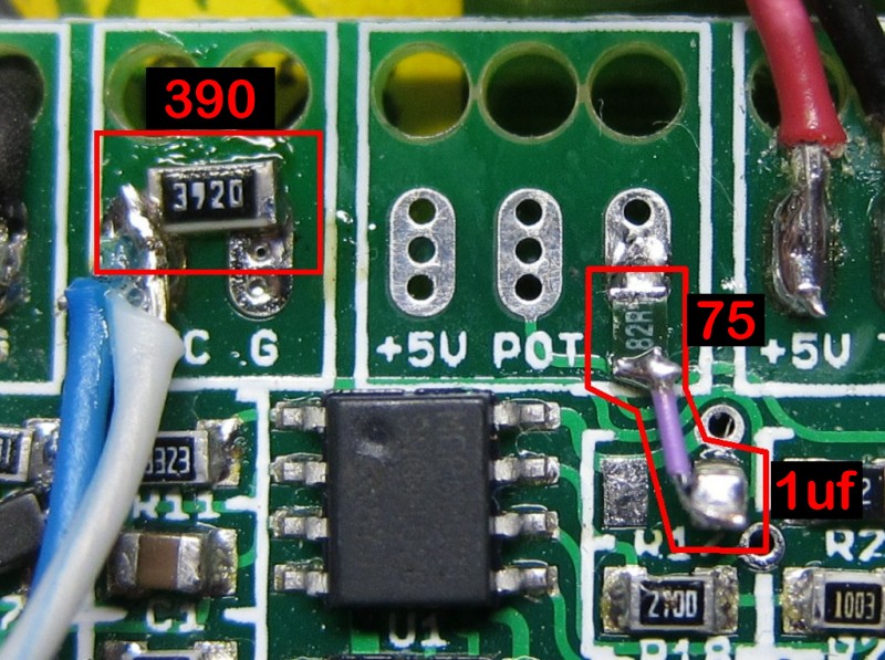
The first step is to remove R17, which is the 5v pullup resistor. Having done this, you'll find however that the Temp input on the CA still tends to float to a high voltage, as there is some leakage from the throttle input line. Thus, a pulldown resistor is needed on the Temp line to sink that voltage to ground. I experimented a bit and found that quite a low resistance is needed. With a 1k pulldown, I was still getting several degrees' worth of coupling. In the end, I settled on the same 390 ohms that I'd originally started with, which seems sufficient to keep the drift to within about 1 indicated degree at 20°.

I was still getting some jitter in the reading when the motor was actually running. My preference would have been to install an R/C filter, as is the common engineering practice when designing automotive ECUs and other such devices. The necessity of the pulldown resistor, however, prevents this. The combination of a pulldown and the series resistor of an R/C filter would create a voltage divider, and we can't have that. So I settled on a compromise, copying circuit from the LM35 datasheet, which uses a 75 ohm resistor and a 1uf capacitor in series, between the NTC line and ground.

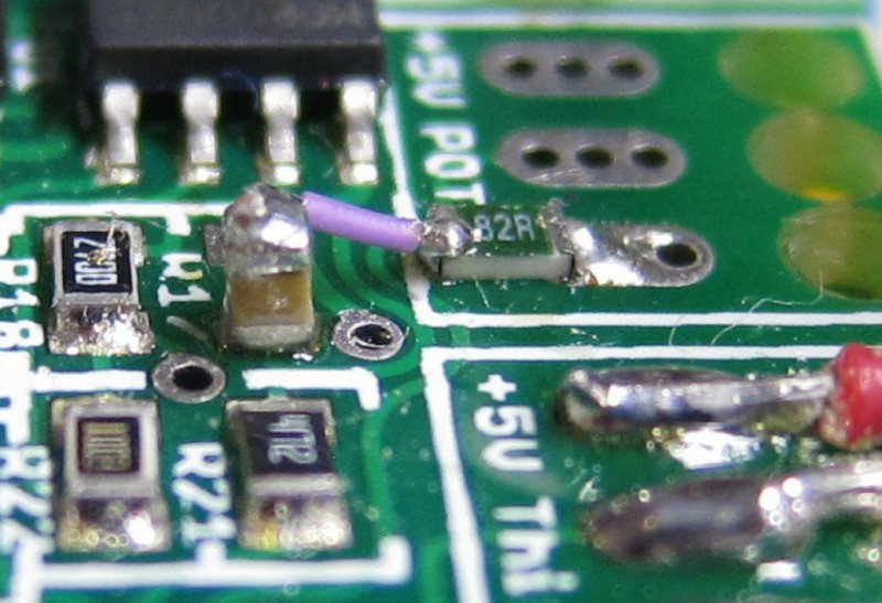
Here's what the finished product looks like:

tsLbZ.jpg


The placement of the capacitor is not obvious in this view- it is standing up vertically on the circuit board, with one end on the R17 pad which connects to NTC, and the other end jumped over to the 75 ohm resistor resting on the ground pad. Here's a side view:

ztAo6.jpg


With this design,I am seeing jitter of only about half a degree when running the system at 20 amps, which I find acceptable. The temperature display is quite jumpy (either a sample-and-hold or some actual averaging in the software would be nice) but it's entirely adequate for my needs. I haven't had a chance to really heat the motor up yet, however I expect that the magnitude of the jitter will diminish as temperature (and, thus, actual voltage on the NTC line) increases.
 
I was just thinking today when I passed some cops: what if the CA had a hidden feature that just set all the trip statistics to say MaxS 25.1mph or MaxPower = 747W. That way when I get pulled over I can explain to them what I was recording and explain to them any discrepancy if necessary (they'd be baffled at how cool it was, more likely, and let me go).

I was reading the indiana laws today, learning that they go by the "Average power." In other words I can run 5HP for 1 second and .55HP for the next 9 seconds and still be at a max average power of 1HP. Maybe an Average power statistic is already included but I missed it.

I want to reiterate how useful it is to have a bar graph to display live readings on-the-go (mainly Power).
 
justin_le said:
That said, from a safety perspective it's a good idea to do as Teklektik suggests and use the fault protection and include a resistor inline with the 5V side of the throttle, so that if you do have a break in the throttle ground return it won't cause full power.

-Justin

In my experience this would be helpful. However, when mine went full throttle in testing with the V2.25 CA, it was because the throttle output to the CA broke (with current throttle enabled). I don't think the CA likes an open connection here. Maybe if the throttle output is not within itermmax/min it should be defaulted to whatever 0 throttle is (Aux threshold in my case). If it was covered already, I apologize for not having caught up yet.
 
Just to be clear I'm not the only person reporting this issue; Teklektik has experienced as well

Okay so I spoke too soon on saying my problems were gone. I had the problem come back to me on a ride and while I was peddling my As- home I figured out how and what is causing the problem. When the throttle cuts out the CA has no output voltage. It snaps back to the minimum throttle settting and reseting etc. only makes it do the same things. Throttle input is fine. Also curiously it only did it after a charge cycle. This got me thinking about what happens when I charge the battery. I always disconnect the battery pack to charge. In my system I have one of those throttles with a button built in. I use this button to turn on/off the small red wire going into the controller. This alows me to easily disable the motor while I'm going up/down stairs or pushing/carrying the bike somewhere.

I'm able to simulate the problem almost every time by hooking up the power with the button off then activating the button. If I turn on the power with the button in the on position it does it as well if i just use the button and leave the battery power to the controller hooked up it works fine. However I have to add that when it quit on my ride last night nothing would reset it. I tried for 4kms before it finally left cutout mode and returned to normal. Must have reset 20 times to get 4 seconds of power each time. It does this in all modes pass-thru, speed, and current. Finally after many power cycles using the button it clears and works perfectly as long as battery power isn't interupted to the controller. If you cycle the power and don't touch the throttle at all for the 4 seconds then you'll find it cut out in your absence.


So more thinking ensued and I think I've got what the problem is. When I wired the throttle I didn't power it from the CA but instead left it powered by the controller. So my theory is that by turning the system on the way I am the throttle signal is live earlier in the boot sequence than expected throwing off the CA somehow. All the values display correctly when the cutout happens except that the output voltage returns to the minimum output.

So could this all be caused by my throttle wiring or did something change between the emailed version and now that makes this a sensitive issue? It's proably only a few msec. in timing but it explains why it always happenes on the way down the driveway. the only fix seems to be to cycle the power till it works. It does not do this with the version you emailed me not even once. So 100% its the software. HOw about some suggestions or more tests I can perform. The microcontrollers I work with have a real time debugger that allows me to look at all the variables while running. I could look furthur with more information or tools.... Maybe we need to record whats happening with an analogger?
 
If you mean, PWM the braking signal? Probably not on most controllers--several of the ones I've tried havea notable delay both in engaging braking and in releasing it, so PWM would be on the order of half a second to a second per cycle, which unless you are braking on a very long downhill isn't going to have time to do much.

If the controllers have a physical RC circuit used to create that delay, then it could be modified or removed so that PWM would be possible at whatever rate the MCU accepts and responds to braking signals, but I don't know how fast that is, either. Probably not very.

I looked into this when I wanted to add a 555 PWM circuit to my ebrake levers a long while back, but never ended up trying it after I realized the delay problem.
 
Hi, total noob on these forums, but I'm a friend of Farfle. I inherited his small screen CA from him when the larger screen version came out, and I had an idea about a possible security feature that could be added to the cycle analyst/ analogger in future versions and this seems like a good place to post the idea. It's pretty basic: an option to use the microSD card in the analogger as a sort of key for your bike.

The way I think it could work is to add a third wire coming out of the analogger (according to this manual I found for the analogger (page 2) http://www.ebikes.ca/drainbrain/CA-LOG_Prelim_Manual.pdf there is an unused connection on the 3.5mm headphone jack) that connects to the RX pin of the cycle analyst and the TX pin of the analogger (haven't gotten to see the schematic or the board for the analogger so I'll just assume there is one). The analogger would then send a string that is stored on the sd card under some file as "bike_password.txt" at startup. If the option is enabled on the CA, if it doesn't receive the string or it doesn't match the stored password, it cuts the throttle input to zero and displays some message like "Bike Locked: Insert Card". The result would be that if some thief can somehow turn your bike on, without the sd card inserted it won't go anywhere.

I realize this isn't a perfect anti-theft solution, and not the CA's main function, but I thought the idea was good enough to pass it along to somebody.
 
folks-

Unfortunately, Justin has suffered the passing of a very close family member and is home with friends and family. He regrets that he cannot pursue this and other business efforts in these trying times but will hasten to resume them in the near future.

I am certain that all our thoughts and sympathies are with him.
Thank you for your patience and support in this time of great personal loss.

-teklektik

EDIT - 6/18 - He's Back!
 
Hi,

I can't decide whether to buy the CA V2 or V3, as I would need it in 2 weeks time.
Any updates as to when the v3 would become available?

Condolences for the loss Justin...
 
Back
Top