E-max 110s lifepo4 upgrade

flexy said:
I have road tested the bike with my ecrazyman 18fet contoller. motor was cogging at slow spped, it smoothed out as I sped up to 20mph, but there was an occasional bump like the motor was missing a beat.
It was drawing 5kw as I climbed a hill , the controller became quite hot and then fets must have blown. :cry:

I think this motor needs a bigger controller, I don't want to risk blowing my Lyen 18fet, so I think I need something bigger.

Can anyone recommend a controller that would work, the Lyen 24fet looks promising, also Kelly controllers, but they have many different versions and I'm not sure which would be suitable.
Hi Flexy!
Are you sure you found the right combination of wires connecting the controller to the motor?
Of the 36 combinations (3 phase and 3 Hall sensors), there are 4 options when the motor is spinning.
1) The motor rotates forward
2) The motor rotates back
3) The motor rotates quickly forward, but has no power.
4) The motor rotates quickly back, but has no power.

I think that your version No. 3. Please check it.
 
yokneamcity said:
Do you know what the rating of that upgraded sevcon for the E-max ,is it 48V or 72V?

ctirad said:
Good question. I have no idea, though. I only know that it can be easily programmed to speeds up tp 70km/h with the original 48V voltage.
How does it work? The speed depends on the voltage.

e-max has speed limiter to 45km/h, but the motor can actually spin faster. In addition, the new controller probably could use field weakening to push the speed even further.
 
ctirad said:
yokneamcity said:
Do you know what the rating of that upgraded sevcon for the E-max ,is it 48V or 72V?

ctirad said:
Good question. I have no idea, though. I only know that it can be easily programmed to speeds up tp 70km/h with the original 48V voltage.
How does it work? The speed depends on the voltage.

e-max has speed limiter to 45km/h, but the motor can actually spin faster. In addition, the new controller probably could use field weakening to push the speed even further.
According to GPS it 42 km/h. :D
 
yokneamcity said:
Hi Flexy!
Are you sure you found the right combination of wires connecting the controller to the motor?
Of the 36 combinations (3 phase and 3 Hall sensors), there are 4 options when the motor is spinning.
1) The motor rotates forward
2) The motor rotates back
3) The motor rotates quickly forward, but has no power.
4) The motor rotates quickly back, but has no power.

I think that your version No. 3. Please check it.

Hi yokneamcity,

I did try all 36 combinations, there were more instances than you state,there seemed to be;
6 instances of forward speed going fast, like in the video
1 instance of smooth slow forward motion
4 instances of slow forward rough cogging
there were the same number of reverse combinations.

I will check all this again but does this suggest the motor is wound differently? I did have the controller set to 'compatible' so it was maybe working with 60 degree and 120 degree hall spacing options.
 
flexy said:
I will check all this again but does this suggest the motor is wound differently? I did have the controller set to 'compatible' so it was maybe working with 60 degree and 120 degree hall spacing options.

I think your wiring was correct. This motor just needs differrent handling than the smaller ones. Try to experiment with different battery/phase current ratios.

BTW, I started to be skeptic about all the magic around IRFB4110. I used to have a 15FET controller in my 2kW scooter which was equipped with IRF1407, which has similar specs as P75NF75. The controller was never get too hot even after long clibming or intensive use of regen even in hot weather. I eventually I modified it from 48V to 60V and it still worked perfectly. Unfortunatelly one time I accidentaly shorted its 5V output to one of the battery terminal and blown the main chip :( So I replaced it with 12FET lyen with IRFB4110, set it to similar values (60V nominal and 50A battery current), but it was so incredibly hot even after short ride even with regen disabled. So I added big heatsink to be sure it will not blow something. A couple of weeks ago I reenabled regen and blown two fets on the first ride :(

So i think the higher specs MOSFETS like IRFB4110 have indeed excellent internal resistance when switched ON (Rdson), but people forget they have also much higher gate capacity. Interesting is that no one of the modders cares about that and they just replace one mosfet for another without a proper compensation in the gate driver circuit. Then the higher gate capacity slows down the switching time and thus increase the power looses, maybe even more one save due to better Rdson specs. Can someone more experienced comment this theory?
 
yokneamcity said:
...But I still have one of these scooters for parts

You should use that motor on a much lighter platform, install a 74V battery pack capable of high power, and find the most powerful controller you can. I'm running a quite similar motor with 20ah of high power batteries and a force air cooled controller. It's installed on a Cannondale SuperV freeride bike with a custom swingarm with a total bike weight of 53kg. I just turned the controller up from 220A to 280A last week, and it's definitely the most fun I've had with my clothes on. The controller is proving to be stable, so after I move it to the downtube for better cooling airflow I plan to turn the controller up again to 350A from the battery. That's over 26kw if I keep the battery voltage from sagging below 74V ! :shock:

Scooter hubbies with 260mm stators rule, but you have to free them of their heavy pig poor handling scooters. 8)

John
 
flexy said:
yokneamcity said:
Hi Flexy!
Are you sure you found the right combination of wires connecting the controller to the motor?
Of the 36 combinations (3 phase and 3 Hall sensors), there are 4 options when the motor is spinning.
1) The motor rotates forward
2) The motor rotates back
3) The motor rotates quickly forward, but has no power.
4) The motor rotates quickly back, but has no power.

I think that your version No. 3. Please check it.

Hi yokneamcity,

I did try all 36 combinations, there were more instances than you state,there seemed to be;
6 instances of forward speed going fast, like in the video
1 instance of smooth slow forward motion
4 instances of slow forward rough cogging
there were the same number of reverse combinations.

I will check all this again but does this suggest the motor is wound differently? I did have the controller set to 'compatible' so it was maybe working with 60 degree and 120 degree hall spacing options.
6 instances of forward speed going fast, like in the video
Of these, only one can be correct
Maybe one of hall sensor is damage?
Next week I'll get the 18Fet controller from Lyen.
And I'll check it with my scooter.
 
ctirad said:
flexy said:
I will check all this again but does this suggest the motor is wound differently? I did have the controller set to 'compatible' so it was maybe working with 60 degree and 120 degree hall spacing options.

I think your wiring was correct. This motor just needs differrent handling than the smaller ones. Try to experiment with different battery/phase current ratios.

BTW, I started to be skeptic about all the magic around IRFB4110. I used to have a 15FET controller in my 2kW scooter which was equipped with IRF1407, which has similar specs as P75NF75. The controller was never get too hot even after long clibming or intensive use of regen even in hot weather. I eventually I modified it from 48V to 60V and it still worked perfectly. Unfortunatelly one time I accidentaly shorted its 5V output to one of the battery terminal and blown the main chip :( So I replaced it with 12FET lyen with IRFB4110, set it to similar values (60V nominal and 50A battery current), but it was so incredibly hot even after short ride even with regen disabled. So I added big heatsink to be sure it will not blow something. A couple of weeks ago I reenabled regen and blown two fets on the first ride :(

So i think the higher specs MOSFETS like IRFB4110 have indeed excellent internal resistance when switched ON (Rdson), but people forget they have also much higher gate capacity. Interesting is that no one of the modders cares about that and they just replace one mosfet for another without a proper compensation in the gate driver circuit. Then the higher gate capacity slows down the switching time and thus increase the power looses, maybe even more one save due to better Rdson specs. Can someone more experienced comment this theory?

I think you may have something there, it has often been under regen that I have blown fets, in fact I did this last night with my Lyen 18fet on my 2KW scooter! The heavier scooters create a lot more energy when braking on regen than an Ebike.
Maybe you could start a new thread about it in the controller section.
 
flexy said:
I think you may have something there, it has often been under regen that I have blown fets, in fact I did this last night with my Lyen 18fet on my 2KW scooter! The heavier scooters create a lot more energy when braking on regen than an Ebike.

But the point is, taht the stock controller wih 15x IRF1407 FETS was only slightly warm with regen on and the same current settings.

Maybe you could start a new thread about it in the controller section.

I'm going to.
 
Hi all!
I've found the right combination to connect the Lyen Infineon controller to the E-max motor.
Hall sensors
Controller/ Motor
Blue-Blue
Yello-Yello
Green-Green

Phases
Controller/ Motor
Blue-Yello
Yello-Blue
Green-Green

One of the combinations was as Flexy conected.
The motor is spinning very fast and current 30 amps with no load.
 
I looked again a video of Flexy. And drew attention to the no-load current. 30A!
76.6V * 30A = 2500Watt no-load
When properly connected current should be about 5A.
 
Glad you got the hall combination worked out :) how is your scooter performing with the new controller? are you using it at 48V or 72V?
I looked again a video of Flexy. And drew attention to the no-load current. 30A!
76.6V * 30A = 2500Watt no-load
When properly connected current should be about 5A.

That current reading is incorrect, I hadn't set the shunt value in the CA, it was set at 1 mOhm but that controller is actually 0.26 mOHM. The controller was still warm so I think you were correct about the hall combination, I will test again when I have my Lyen controller repaired.
 
Nice work here!
Powerful 5kw hub in a small wheel. Does it take off quick?

Tommy L sends.... \\m//
 
Today I did a test drive with the new controller 18FET Infineon.
Cycle Analyst showed a maximum power of about 2 KW. (This is the default setting of the controller)
I wanted to go home and change the controller settings to 5 KW and try again. But as I placed the controller under the seat, and he did not have enough air flow, strongly heated. Phase connectors were also hot. I think the standard connectors are not suitable for high currents and need to be replaced by more powerful. These are the example http://www.hobbyking.com/hobbyking/store/__6580__8MM_gold_connectors_12_pack_.html.
I decided to change my 18FET controller to a more powerful 24FET and to continue the test drive :D
And to set the controller in such a position that he had sufficient airflow.
 

Attachments

  • Hobbyking_connectors.JPG
    Hobbyking_connectors.JPG
    40.9 KB · Views: 4,077
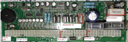
I found a way how to activate the MCU unit without 48V
Pin 8, 12 volt feedback, controls the relay. The relay sends 48 volt to 48/12 Volt regulator.
It is possible to connect 12 volts from external DC/DC (78V to 12V) to the output of the Voltage regulator on MCU board.
 
yokneamcity said:
It is possible to connect 12 volts from external DC/DC (78V to 12V) to the output of the Voltage regulator on MCU board.
Can you show where that connects on the MCU?
 
flexy said:
yokneamcity said:
It is possible to connect 12 volts from external DC/DC (78V to 12V) to the output of the Voltage regulator on MCU board.
Can you show where that connects on the MCU?
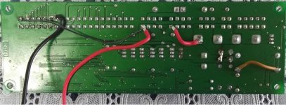
Sorry for the late reply. I connected it in this way.
+12V to CN1_pin8,CN3_pin1,CN5_pin1.
-12V to CN1_pin13/14.
I unsoldered Q3. This mosfet worked in PWM mode and supplying 12 volts to the light (from 48 volts).
I shorted R58/R59 resistors for the signal horn.(Now it work with 12V instead 48V)
I also unsolder the relay and short it. But do not necessarily.
 

Attachments

  • MCU_1.jpg
    MCU_1.jpg
    96.7 KB · Views: 1,341
  • MCU_2.jpg
    MCU_2.jpg
    59.9 KB · Views: 1,341
:D that's some good work.. was your MSU covered in the black epoxy?
 
Mine has the black epoxy so I can't do those modifications you show.

I have ordered a greentime 36fet controller with IRFB4110 fets , hopefully that will handle the power requirements of the motor.
 
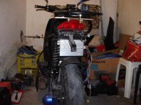
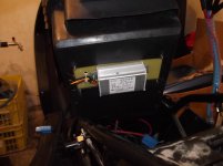
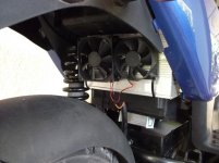
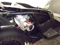
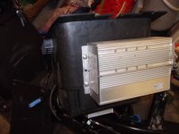
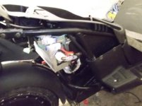
I installed the 24FET Infineon on my scooter. The controller did not get enough air flow and strongly heated. I added it to the two fans, and it solved the problem. Instead of the original controller, DC / DC converter for 12 volt.
Top speed increased from 42 km/h to 50 km/h (52V battery)
Significantly increased dynamics. Maximum current of 100 amperes at the start.
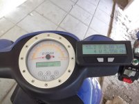
The original speedometer is connected to the green wire in the Cycle analyst connector .
 

Attachments

  • DSCF1708.jpg
    DSCF1708.jpg
    72.8 KB · Views: 3,714
  • DSCF1707.jpg
    DSCF1707.jpg
    58 KB · Views: 3,714
  • DSCF1711.jpg
    DSCF1711.jpg
    62.3 KB · Views: 3,714
  • DSCF1712.jpg
    DSCF1712.jpg
    81.2 KB · Views: 3,714
  • DSCF1714.jpg
    DSCF1714.jpg
    65.7 KB · Views: 3,714
  • DSCF1709.jpg
    DSCF1709.jpg
    60.9 KB · Views: 3,714
  • DSCF1704.jpg
    DSCF1704.jpg
    61.6 KB · Views: 3,714
  • DSCF1709.jpg
    DSCF1709.jpg
    60.9 KB · Views: 3,713
That's a tidy installation, nice!

I'm surprised you are getting that controller hot, I expected it to handle the power better.

Maybe when you raise the voltage it will run cooler, more volts=less amps?
 
flexy said:
That's a tidy installation, nice!

I'm surprised you are getting that controller hot, I expected it to handle the power better.

Maybe when you raise the voltage it will run cooler, more volts=less amps?

Thank You!
It handle the power. Efficiency of the controller is not 100 percent. Part of the power converted into heat. We must help the controller to dissipate the heat on his body.
 
Back
Top