Cycle Analyst V3 preview and first beta release

justin_le said:
Hey everyone, while I was away there was still a bunch of activity here at the shop and the 50 pcs pilot batch that I alluded to some time ago got completed last week, thanks largely to Michael and Mark.
Thanks, Michael and Mark!
Much appreciated!!! :D
 
Hey Justin, That great awsome device is not on my zero motorcycle :mrgreen:

I also explaned how to connect it with detailed pictures :wink:

Seriously that's what is missing on a zero !

Link:
http://www.endless-sphere.com/forums/viewtopic.php?f=10&t=40849


file.php


file.php


Doc
 
Justin, glad to see you back. I've been thoroughly enjoying my CA3 for the past week or so since I've had the new bike finished- great performance on the temp gauge, the throttle re-scaling, and the current limiting. All very smooth.

Since you mentioned the battery SOC indication, and realizing that the SOC gauge in beta14 is known to be incomplete, I figured I'd share something odd I've noticed, on the off chance that this isn't already a known behavior. As background, I'm running Beta14, using a controller with a 1 mohm internal shunt, and a 16S LiFe battery (Cell_Man's triangle.) I have not yet calibrated Rbatt.

When I first start off the in the morning, battery voltage is high enough to drive the SOC gauge to full and keep it there. But once I've ridden a bit, and thus knocked the battery's voltage down far enough to get the SOC gauge off of full, I can see a very bizarre behavior. Essentially, the indicated SOC is positively tracking the current through the system. As current increases, the SOC gauge goes UP, even though battery voltage tends to decrease during this condition.

I took a short video to demonstrate this, in which I've disconnected the rear brake sensor so I can use the brake to force the system into a high-current condition, thus simulating an actual riding load. It is definitely tracking current rather than throttle, as I can hold the throttle at full and use the brake to modulate the current while both ThrottleIn and ThrottleOut remain constant. It helps if you can hear the audio as well, as listening the the motor while watching the Current and SOC gauges is easier than trying to read my annotations.

[youtube]94kVG-OMeJU[/youtube]

Does this seem odd?
 
I think the Rbatt setting is used by the CA to prevent this from happening, when the CA knows the packs IR it can compensate for the voltage drop under load to maintain the fuel gauge at the correct level.

I asked Justin a question about this, my question is at the bottom of page 21 of this thread and justins answer at the top of page 22.

Simon.
 
I saw that, along with his note that "If you are running LiFePO4 just ignore the fuel gauge until the Ah accumulation is integrated in the beta software here."

Since I am running a LiFePO4 battery, I understand that it's not up to par yet, this particular behavior just struck me as exceedingly odd. I'll try calibrating Rbatt and see if that makes it behave more logically- based on Justin's post on page 14 (where RBatt = (V1 - V2) / A) it looks like I should configure it as 066 (it's at the default 199 right now)
 
justin_le said:
marty said:
One more suggestion. How about a large screen showing graphics only? Battery State Of Charge Indicator, Throttle Position Slider, Human Power Bar Graph, and miles or kilometers per hour, (speed)
Like this:

Unfortunately the CA doesn't use a graphics screen, so it can only show number and letter characters and then a few graphical 'hacks' within a 5x8 character grid which you see in this one here. It doesn't lend itself well to showing predominantly visual indicators. Someday Marty a full graphic display will be in the cards and you will get your long awaited wish, but not yet! gotta grow one step at a time.

What BionX and almost all other consoles do is use a custom segmented LCD screen tooled up that exactly matches the info they want to display. It's very economical in scale, you don't need to do any graphics processing in a CPU, but it's also single function in nature and so doesn't lend itself to the kind of multi-purpose display flexibility that the CA needs.

-Justin

I still think simple sliders are very doable on this CA.. They don't have to be super pretty but they could be big enough to be useful. Even the battery indicator as is to me is not something that would give me enough resolution as a casual observer.

It looks like horizontal indicators would be most practical to use and easy to program. Maybe there could be an option to dedicate the top or bottom half of the screen to a parameter option. Even dividing the bottom half into too sliders could be easy to program.

I have not seen your code but obviously requires some rework, so I can maybe see it as a low priority. I would think the code would be redundant enough to make it less taxing
 
Joe Perez said:
(...) I'll try calibrating Rbatt and see if that makes it behave more logically- based on Justin's post on page 14 (where RBatt = (V1 - V2) / A) it looks like I should configure it as 066 (it's at the default 199 right now)
Well that's just darned interesting. With Rbatt set to 066, the strange behavior in the SOC indicator went away. I'd really love to know what the algorithm is which is driving that display. (edit: Oh, I get it now. Rbatt is used as a compensation relative to instantaneous current, to compensate for voltage sag under load. That way the gauge doesn't fluctuate as the load causes battery voltage to go up and down. Genius!)

Ah, well. All in all, this CA3 is just absolutely phenomenal.

Something amusing occurred to me over the weekend. When I saw a lot of folks in this thread making impassioned suggestions about table-based (or otherwise non-linear) throttle scaling, I couldn't figure out what the big deal was. Of course, at that time I was riding with an Amped Bikes direct-drive motor (2807) and an anemic 36v bottle battery, so for me, the idea that you'd ever need anything less than 100% throttle all the time seemed unfathomable. (translation: the Amped system is weaksauce.) Now that I've upgraded to a 10T geared MAC and a Cell_Man 52v battery, I suddenly understand what all the fuss is about. It's kind of hard to keep this thing from wheelieing if you accidentally apply more than 0.05% throttle from a stop. :mrgreen:

Actually, now that everything is up and running, I probably need to experiment with current-mode throttle, as opposed to pass-through as I have it now. That alone would probably make things a lot easier. Off to do more reading.


At any rate, Justin, this is a hell of a great product. I seriously cannot express in words how much I like what you've created here.
 
Joe Perez said:
I saw that, along with his note that "If you are running LiFePO4 just ignore the fuel gauge until the Ah accumulation is integrated in the beta software here."
Since I am running a LiFePO4 battery, I understand that it's not up to par yet, this particular behavior just struck me as exceedingly odd. I'll try calibrating Rbatt and see if that makes it behave more logically- based on Justin's post on page 14 (where RBatt = (V1 - V2) / A) it looks like I should configure it as 066 (it's at the default 199 right now)

Hi Joe, indeed this behaviour is coming from an incorrect (too high) battery resistance value. When you are drawing current, the CA tries to extrapolate what the actual pack voltage would be with no current before it references the lookup table. So suppose you are drawing 10A, and reading 47V from the pack. If RBatt was set to 200 mOhm, then the CA would assume your actual battery voltage is:
47 +10A*0.2 Ohm = 49V

If your actual RBatt is only say 100mOhm, then the actual open circuit voltage of the pack is more like 48V
47 +10A*0.1 Ohm =48V

If you then increase the current draw to 20A, the voltage on the pack would fall down from 47V to 46V, but the CA would overcompensate even further when extrapolating the open circuit pack voltage, now to:
46 + 20A * 0.2 Ohm = 50V.

So this is why with RBatt too high, you have an effect where drawing more current causes the battery indicator to go up. Once you play around with it you can find a value that causes the graph to neither go up or down with increased load.

This is however somewhat moot as the Beta15 code no longer lets you input the RBatt value. Instead, it computes it in real time, and this allows it to track your changing battery resistance both as it ages and as it varies with temperature and state of charge. So there is now a new screen which lets you see the instantaneous RBatt value that the CA has deduced from watching the recent voltage/current history, and you as a user no longer need to worry about setting this up:

 
Joe Perez said:
I'd really love to know what the algorithm is which is driving that display. (edit: Oh, I get it now. Rbatt is used as a compensation relative to instantaneous current, to compensate for voltage sag under load. That way the gauge doesn't fluctuate as the load causes battery voltage to go up and down.


This came in after I had already written but forgot to submit the previous post, but yes spot on. However, the Beta15 algorithm does things on the display quite a bit differently in that it is also looking at your amp-hour history. The look-up table approach gets increasingly inaccurate as you draw more and more current, so in this situation the CA3_B15 weights more heavily towards looking at your change in amp-hours to determine how the SOC should go down, and increasingly ignores the look-up table value.

At the end of the day though, amp-hours can go in and out of the pack without the CA knowing and this in and of itself causes an amp-hour based approach to SOC display to fail. So whenever there is relatively little current draw, then the CA will see where the open circuit pack voltage is at and gradually cause the SOC graph to drift towards that.

It's the kind of thing that was conceptually pretty straightforward to work out, but a bit of a challenge to implement on an 8-bit micro, so that's why it's taken a while to roll this out.

Now that I've upgraded to a 10T geared MAC and a Cell_Man 52v battery, I suddenly understand what all the fuss is about. It's kind of hard to keep this thing from wheelieing if you accidentally apply more than 0.05% throttle from a stop. :mrgreen:

Indeed had to have a similar realization test riding other people's ebikes before appreciating this too ;). That happened after years of wondering what the fuss was about 3-speed switches.

-Justin
 
So attached here is the B15 version of the CA3 code. Please note that I've only had a few hours to field test on the bike and haven't run through nearly all usage scenarios, so there may be newly introduced bugs but to a first order it seems OK.

Differences with Beta14 are:

1) No longer a field to input RBatt
2) Battery SOC algorithm now takes into account the pack capacity in Ah, so be sure to input this value in the battery setup.
3) Display Screen # 10 shows Volts, Amps, RBatt, and %SOC
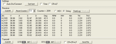
4) Serial data output stream has been modified to include the throttle input and throttle output voltages as well, and gets rid of the instantaneous torque (but still includes average torque). A screen capture of the data stream looks like this:

CA_V3_Output.gif
 
Very nice, very useful. V3 keeps getting better and better, and I love it! Thanks, Justin!
 
Setup Summary for CA v3B15

The setting summary for the newer v3B16 release is available here.
The setting summary for the previous v3B14 release is available here.
Unofficial basic setup notes are available here.
Values shown are defaults after loading firmware.

[...] = numeric entry field
{ ... | [...] } = menu chooser where [...] = default selection

  1. Setup Calibrtion
    1. Cal -> Range
      { [Lo (W)] | Hi (kW) }
    2. Cal -> RShunt
      [1.000] mOhm
    3. Cal -> V Scale
      [31.05] V/V
    4. Cal -> Zero Amps
      (Press/Hold to normalize the currently detected Amp reading to 0.0)
  2. Setup Spdometer
    1. Spd -> Units
      { mi | [km] }
    2. Spd -> Wheel
      [2075] mm
    3. Spd -> #Poles
      [23]
    4. Spd ->TotDist
      [00000] km
  3. Setup Speed Lims
    1. SLim -> Max Speed
      [99.0] kph
    2. SLim -> Start Speed
      [00.0] kph
    3. SLim -> IntSGain
      [200] Gain
    4. SLim -> PSGain
      [0.59] V/kph
    5. SLim -> DSGain
      [002] Gain
  4. Setup Power Lims
    1. Plim -> Max Current
      [99.0] Amps
    2. Plim -> AGain
      [150] Gain
    3. Plim -> Max Power
      [9999] Watts
    4. Plim -> W Gain
      [050] Gain
  5. Setup Throt In ........ Live Data = < 0.00V >
    1. ThrI -> Cntrl Mode
      { [Pass-thru] | Current | Speed | Disabled }
    2. ThrI -> Min Input
      [0.99] Volts
    3. ThrI -> Max Input
      [3.99] Volts
    4. ThrI -> Fault Volt
      [4.49] Volts
  6. Setup Throt Out
    1. ThrO -> Output Mode
      { [Voltage] | R/C Pulse }
      (if ThrO->OutputMode = { Voltage }
      1. ThrO -> Min Output
        [0.90] Volts
      2. ThrO -> Max Output
        [3.74] Volts
        )
      (if ThrO->OutputMode = { R/C Pulse }
      1. ThrO -> Min Output
        [0.90] mSec
      2. ThrO -> Max Output
        [3.74] mSec
        )
    2. ThrO -> Up Ramp
      [500]
    3. ThrO -> Down Ramp
      [500]
    4. ThrO -> KV Comp.
      [0.95] V/kph
  7. Setup RPM Sensor ........ Live Data = < Rev Hi > >
    1. RPM -> PAS Poles
      [08]
    2. RPM -> Dir Plrty
      5v={ [Fwd] | Rev }
    3. RPM -> Quadrtr
      { Disabled | Enabled }
    4. RPM -> Strt Delay
      [25] x 18ms
    5. RPM -> Stop Delay
      [15] x 18ms
  8. Setup Trq Sensor ........ Live Data = < 3.37V >
    1. Trq -> Trq Scale
      [-200.0] Nm/V
    2. Trq -> Trq Offset
      {2.49V 2.43V}
      (Press/Hold to update eeprom offset voltage on left with current voltage on right - similar to Zero Amps)
  9. Setup Cntrl Mode
    1. Ctrl -> PAS Mode
      { [PAS Off] | RPM Cntrl | Trq Cntrl }
    2. Ctrl -> Assist Level
      [0500] mA/Nm
    3. Ctrl -> Aux Funct
      { [Off] | Amps Lim | Speed Lim | Power Lim | Pas Level }
    4. Ctrl -> Min Aux In
      [0.99] Volts
    5. Ctrl -> Max Aux In
      [3.99] Volts
  10. Setup Temp Sensr
    1. Temp -> Sensor ........ Live Data = < 4.93V >
      { [Disabled] | 10K Thrmstr | Linear Type }
      (If Temp->Sensor = { Linear Type }
      1. Temp -> 0 Deg
        [0.99] Volts
      2. Temp -> TScale
        100.0 Deg/V
        )
    2. Temp -> Thrsh Temp
      [090] oC
    3. Temp -> Max Temp
      [130] oC
  11. Setup Battery
    1. Batt -> Chemistry
      { [LiMn] | LiPo | LiFe | SLA | NiMH }
    2. Batt -> String#
      [10] Cells
    3. Batt -> Capacity
      [10] Ah
    4. Batt -> Vlt Cutoff
      [019.0] Volts
    5. Batt -> V Gain
      [0800] Gain
    6. Batt -> TotCyc
      [0000] Cyc
    7. Batt -> TotAhrs
      [00000] Ah
  12. Setup Display
    1. Disp -> Main Disp
      { [Watts] | Amps }
    2. Disp -> Averaging
      [5] Duration
    3. Disp -> RS232
      { [1] | 5 } Hz
    4. Disp -> Vshutdown
      [10.0] Volts
    5. Disp -> Stop Scrns
      [11111111111]
      (Binary digits select display of 11 screens starting with Main)
    6. Disp -> Movn Scrns
      [11111111011]
      (Binary digits select display of 11 screens starting with Main)

Printable version: View attachment CA_3B15_ConfigSettings.zip
 
Thanks Teklektik, got myself a cable, laptop accepts it, com port i dentified, b15 downloaded, i just need to print one of your sheets off, note down my current settings and i am going to have a go at installing the new version, Prepare to get bombarded with questions when i no longer have a bike that works! :shock: :roll: This will be a first for me, never flashed a device before.

Simon.
 
johnrobholmes said:
What is the time span the torque is averaged over?

Great question. It's actually averaged over each full pedal rotation rather than over a time span. This way there is no undulation from the pulsating human pedal torque aliasing with the average rate in different ways. However, it also means that the torque signal is pretty useless (ie won't change) unless you similarly have an RPM meter hooked up. For use in a dyno type application on fast spinning motors, then the torque value would be nearly instantaneous as the motor is probably doing several revolutions between each data transmission.

-Justin
 
I just have to say. I'm very impressed with this new version of the CA and all the discussion here.

This thread is chock full of goodness. :)
 
Joe Perez said:
Actually, now that everything is up and running, I probably need to experiment with current-mode throttle, as opposed to pass-through as I have it now. That alone would probably make things a lot easier. Off to do more reading.
Yup, that did the trick. Still running B14 (will probably put off the upgrade until this weekend) but current-mode throttle *really* improved the controllability.
 
I notice that speed less than 4 mph does not show on the display, nor is it in the data file record.
With CA2 V2.25 the lowest indicated speed is 2.5mph.
Wheel = 2105.
It would be great if the CA could show speed aproaching 0.00.

Waldo
 
Waldo said:
I notice that speed less than 4 mph does not show on the display, nor is it in the data file record.
With CA2 V2.25 the lowest indicated speed is 2.5mph.
Wheel = 2105.
It would be great if the CA could show speed aproaching 0.00.

Waldo

I am using a wheel driven speed sensor on my CA, i tried fitting 3 magnets to the disc spider but their strength and proximity caused a field too strong for the reed switch to release. If you can use multiple evenly positioned magnets and change the pole count accordingly it is bound to give a higher resolution to your signal and may allow it to function at lower speeds?
 
Waldo said:
I notice that speed less than 4 mph does not show on the display, nor is it in the data file record.
With CA2 V2.25 the lowest indicated speed is 2.5mph.
It would be great if the CA could show speed aproaching 0.00.
I use three evenly-spaced spoke magnets and get speeds down to about 3.25-3.45 mph which is fine for me. This was a quick test a couple of minutes ago, but a sudden downpour ended the test after only a couple of tries, but I don't think it will go much lower.

A single magnet was working fine (I never bothered with super low speed checks) but upgraded to try to smooth out low speed 'Speed Throttle'. With only a single magnet I was only getting a speed update about every 6m (very delayed feedback to the CA compared to 20-something motor poles) - with three, it's about every 2/3m. Other pressing matters prevented finishing up those tests, but I'm hoping to return to them shortly.

Tench said:
I am using a wheel driven speed sensor on my CA, i tried fitting 3 magnets to the disc spider but their strength and proximity caused a field too strong for the reed switch to release.
Clever idea. If you haven't abandoned that setup entirely, you can try attaching a small magnet with reverse poles to your pickup. This works pretty well in general with reed switches - sometimes you need to position it away from the center of the switch towards one end.

Tench said:
... If you can use multiple evenly positioned magnets...
Although in this case your recommendation is clearly going after more frequent and evenly-spaced updates, Justin reports that in the general case, additional wheel magnets do *not* need to be evenly spaced. This is nice since, for instance, on my bike my 'evenly spaced' options are 1, 3, and 9.

BTW - Although spoke magnets from just about anywhere will work, ebikes.ca will sell them individually - if you're thinking on these lines, email and have them throw a few in the box when you order your new v3.
 
Back
Top