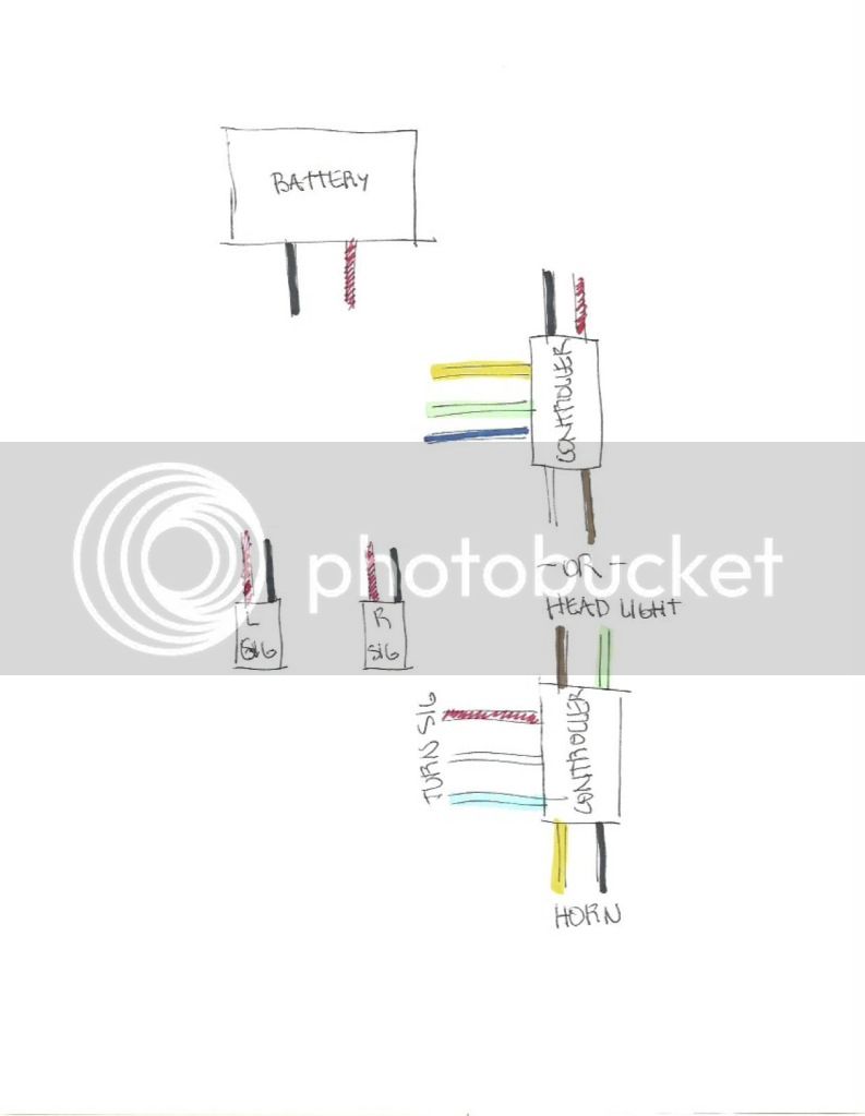
Thank you so much kingfish and especially Cohberg for your help. It was Cohberg's diagram that ultimately got my project working. Thanks so much again for your time and effort in creating the wiring diagram specific to my controller and of course for helping me identify what wires do what.
So that you know your effort didn't go to waste, I wanted to show you that the project really did work! And it's you I have to thank for the success of this turn signal project.
PARTS:
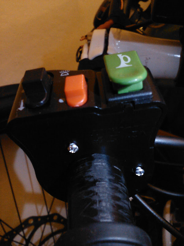
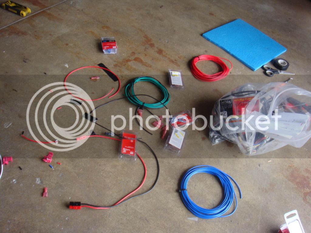
- handlebar controller (ebay, $8 or so)
Yes, it's true that the one I have is of poor quality. No doubt about that, but it works.
- wires (ebay, $11 or so)
You can get a variety of colors in a set rather than buying them individually. Home depot has wires too by the length.
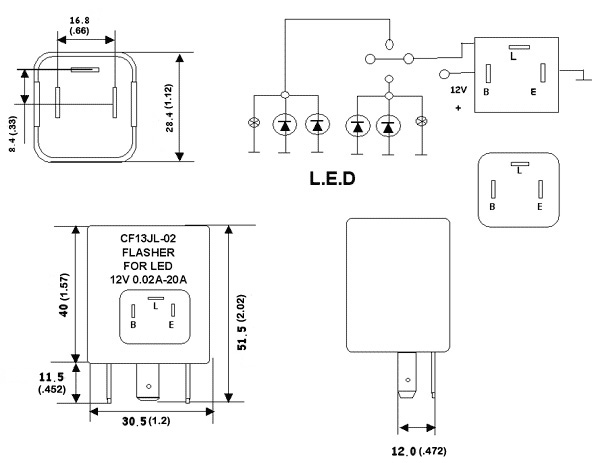
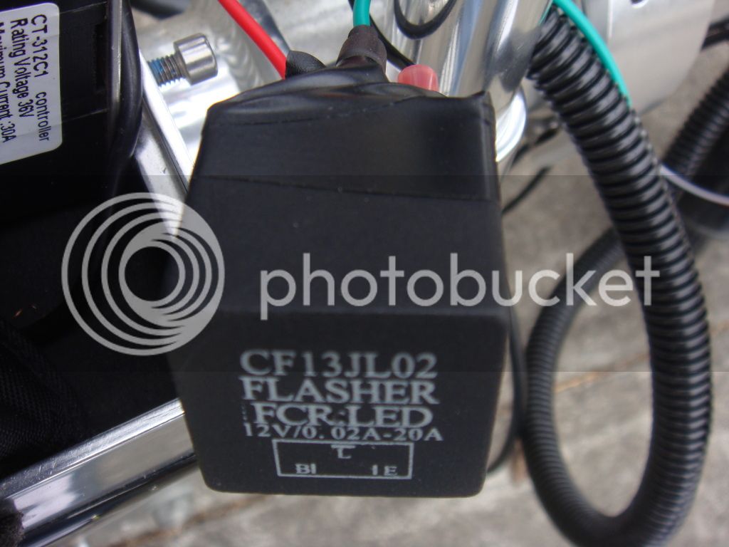
- 3 pin flasher (ebay, $1.50 shipped)
As far as I know, they're all the same. Just get the cheapest one and wait for it to arrive in the mail.
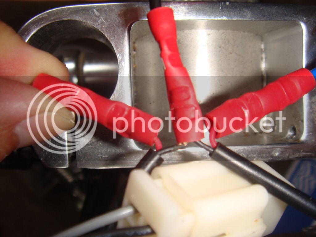
- butt connectors (Oreilly Auto Parts, $4)
The controller's wires aren't long enough and you'll need this to extend the wires the correct way.
- other type of connectors (True Value hardware, $3)
If you want any connections to be easily removable, get that type of connector. I don't know what it's called, but you'll want the ones that will connect the wires to the flasher easily.
- heat shrink (True Value hardware, $3)
This is sort optional but is recommended for "waterproofing."
- electrical wire tape (garage, free)
I already had this laying around, but get a roll. It's worth it.
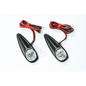
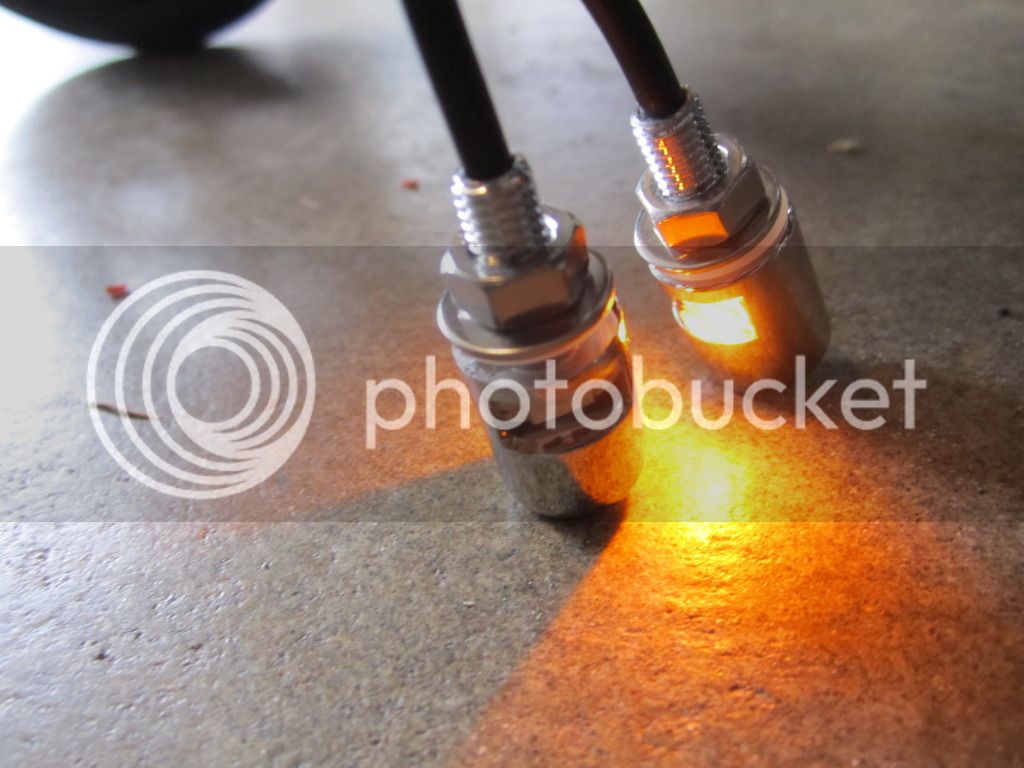
- license plate bolts (ebay, $8)
The bolts I described above are for car license plates, but I rotated the orientation to use them as turn signals. Be sure to get the amber colored ones if you're using this type.
- wire management (Daiso japanese dollar fifty store, $1.50)
This just makes for a cleaner look. I don't like wires everywhere. Also protects it from the elements.
- quick splice connectors (True Value, $3)
TOOLS:
- wire stripper
- wire cutter
- wire crimper
It may help to see how the end product looks like before starting on it yourself. Again, thanks so much Cohberg for creating the wiring diagram for me. I honestly wouldn't have been able to do it alone. Much much appreciated. By the way, I'll send you a few bucks via Paypal as a donation for your effort if you want. Just PM me your Paypal email address.
[youtube]rZYSpm9m7ok[/youtube]
STEP 0:
Unplug your power source.
STEP 1:
Purchase all the parts. I decided I wanted a clean installation, so I purchased a set of wires that are color coded to match the controller I bought. I'm new to all this and I didn't want to get confused by using all black wires and not knowing which one is which. The color coded wires help and for the price, it's decent. The wires coming out of the controller weren't long enough so I wanted the wire wire extension to be white, the green one to be green, etc. Buying them in packs are pricey so I got some short lengths from ebay in a variety of colors.
STEP 2:
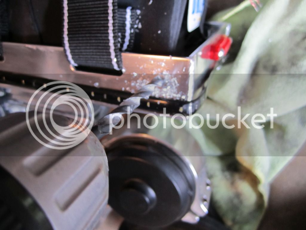
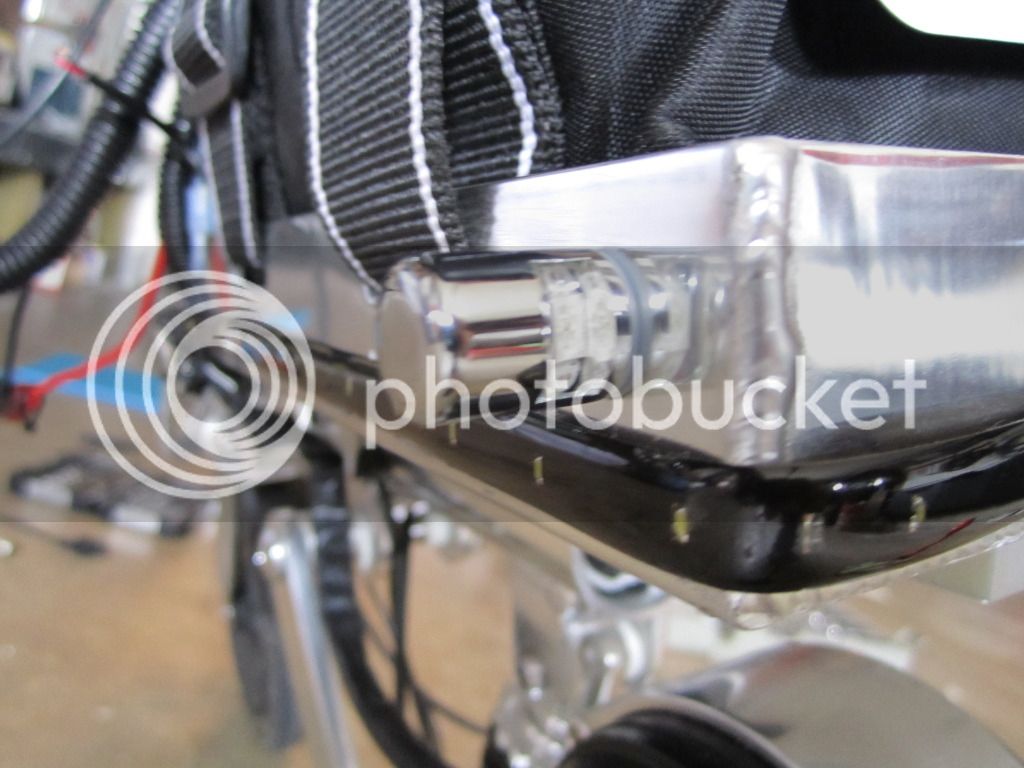
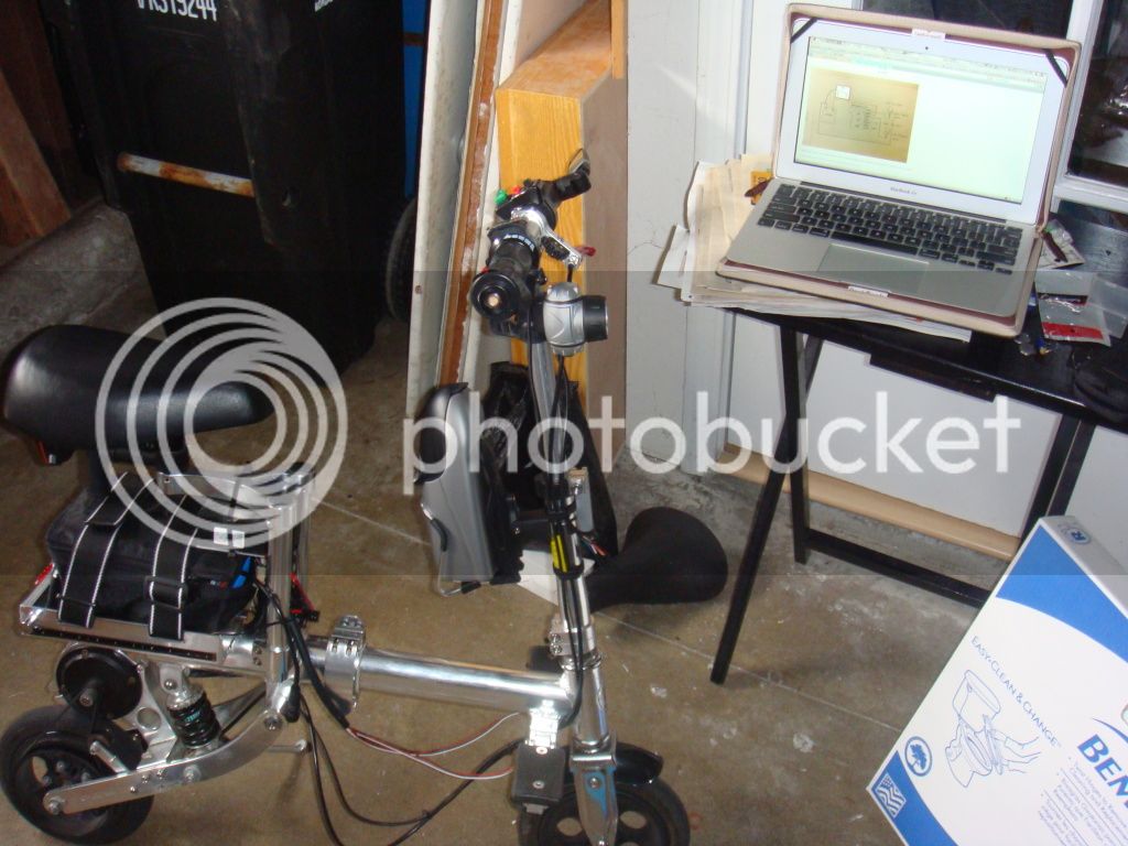
Mount your components, mainly the handlebar controller and the lights. Adjust the angle and location so that it's perfectly the way you want it. Decide where you want to mount the flasher. Your wire lengths will be determined by this and the proximity to the battery.
STEP 3:
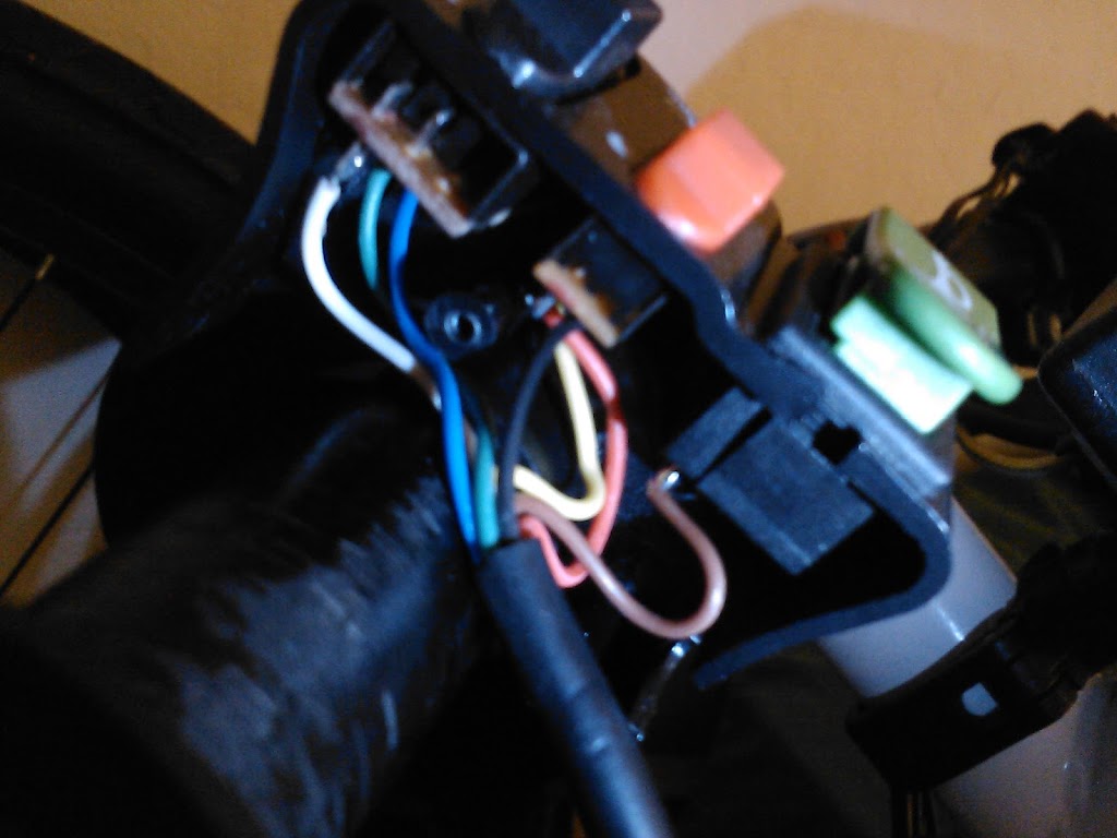
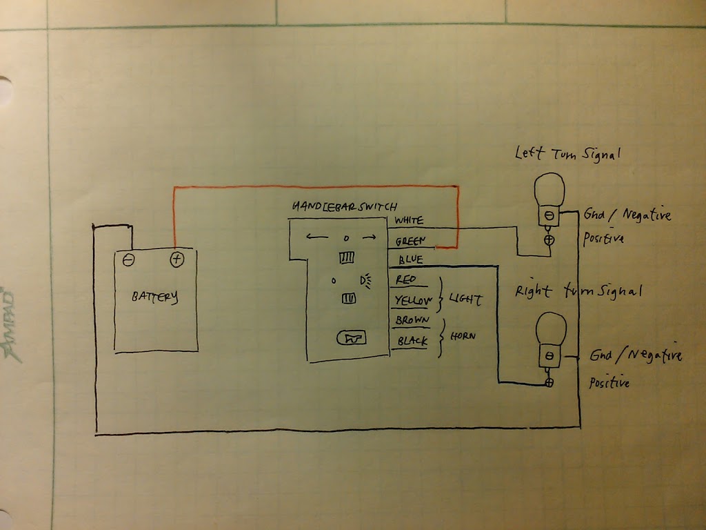
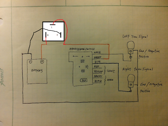
Identify the wires. Use Cohberg's wiring diagram! In the case that you're using a different controller from the one I used above, use his method for identifying what wire does what. Pretty much just open up that puppy and see what color wire is leading to which switch. Pretty easy and helped me tremendously.
STEP 4:
Extend the controller wires to the proper length. The green, blue and white wires all needed to be lengthened to reach the battery. Measure and connect these wires to the wires coming out of the controller using a butt connector. Use heatshink too if you want. How to use butt connectors? Look it up on Youtube, it's as easy as you think it is. Strip the end of the wire, put it into the butt connector hole, and crimp it.
STEP 5:
If needed, extend the red and black turn signal wires to the battery area. My scoot's way short, so I didn't need to extend it.
STEP 6:
Splice the white wire from the controller to the red wire on the left turn signal using a butt connector.
STEP 7:
Splice the blue wire from the controller to the red wire on the right turn signal using a butt connector.
STEP 8:
Connect the green controller wire to the flasher. This simplifies things b/c now you only have two more pins on the flasher that need something to connect to.
STEP 9:
If you get nervous and don't want to splice your power wires just yet, you can try connecting the proper wires from the diagram temporarily to the battery just to see if the turn signal functions as intended. If it does, then you can go ahead and splice permanently
STEP 10:
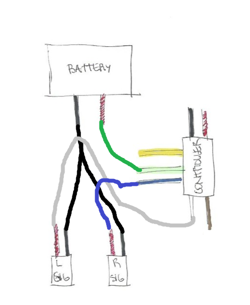
This is where it gets complicated. Just follow Cohberg's diagram and it'll be fine. The reason it's tough is b/c our battery is not only being used to operate the turn signal. Chances are that you're using the battery to power your bike as well. This means a lot of splicing of wires.
There's just a lot of wires to keep track of and to make it clean looking is a bit of an effort. You should now still have one black wire coming out from each of the turn signals that aren't connected to anything. This part is complicated b/c both black wires from the turn signals need to be connected to a single wire and the other end of that wire needs to split off again to splice into both the battery and the flasher. You'll spend most of your time on this step.
First just splice the two black wires from the turn signal to a single black wire. You can twist the two wires and just butt connect them into a new black wire to create a Y-shape.
STEP 11:
Splice the turn signal ground wire from step above into the battery and into the flasher. You must still maintain the connection from the battery to the motor of your ebike/escoot. So that means there's an extra splice that's not shown in the wiring diagram. Since my battery is more expensive than my motor, I decided to splice into the power wires on the motor rather than the power wires on my battery. This was also a very conscious decision b/c I wanted my battery to be easily removed independent of this system so that I could use it on another ebike (which I plan to do often).
STEP 12:
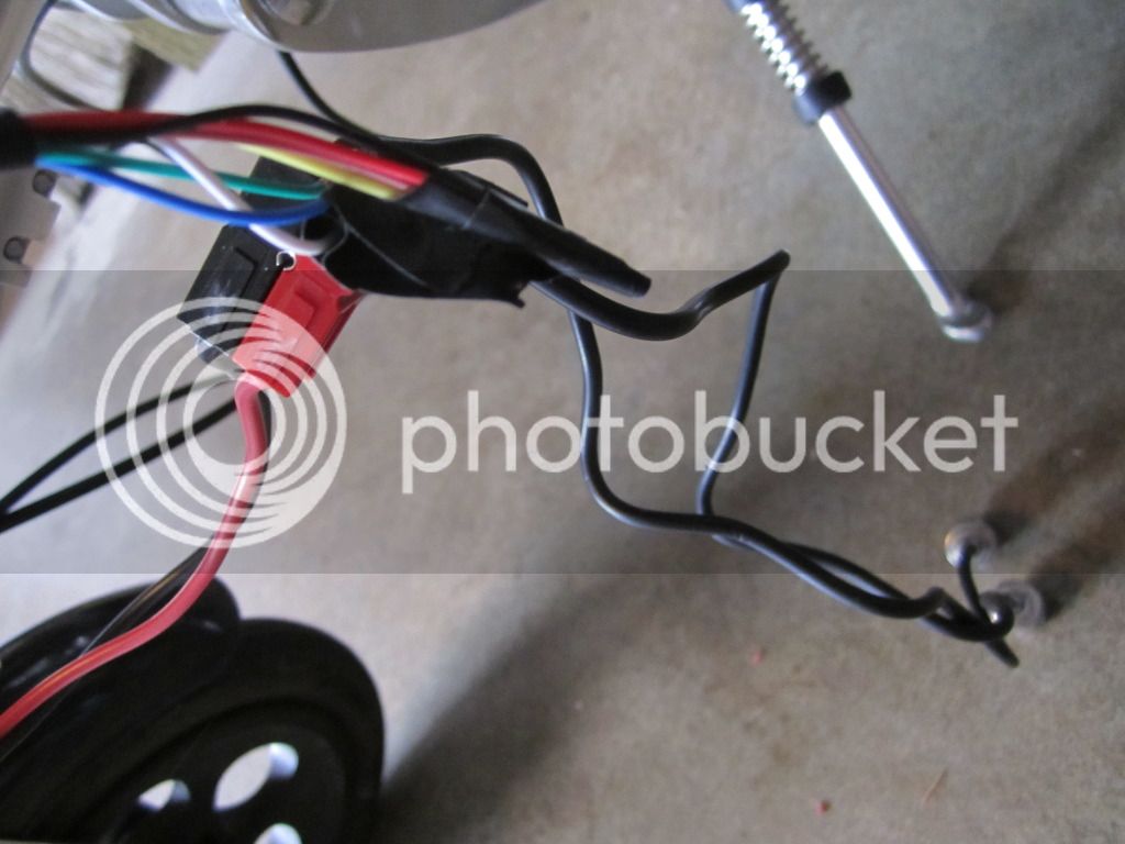
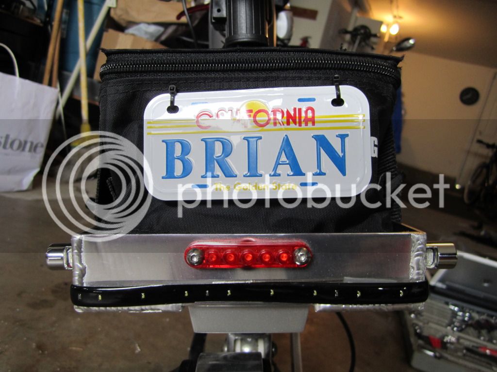
Test it again and hopefully it works and looks like this:
[youtube]IfZp73Pw-Hc[/youtube]
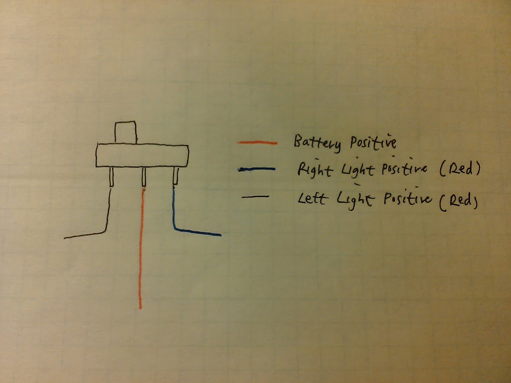
THE ONLY HUMP:
The only hump I came across was that I got the negative and positive poles on the flasher reversed. Typically flashers are labeled on the top side so that you can rotate it 90 degrees to see what pin does what. L is obvious since it's at the top, but the E and B aren't so obvious for amateurs like myself. My flasher was labeled on the opposite side of where the pins are which is not the typical standard. I had accidentally mirrored the E and B pins. Once figuring out my mistake, I swapped it and bingo! It worked.