Reverse polarity with my controller

cwah

100 MW
Joined
Jul 24, 2011
Messages
4,256
Location
Between paris and london
Hello guys,

Today I was a bit drunk after meeting friends, and wasn't walking very straight but still wanted to ebike. But for some reason, when I tried to add the parallel plug between my battery and the controller, I must have plugged everything in the wrong way and smoke was coming out of my cable.

The bullet connectors were melted and the battery wire from the controller has the plastic completely melted:
controller_1.jpg


The 2 black and red wires were melted together and I had to dissociate them.


But now the controller isn't working anymore. When I plug the direct plug of the cycle analyst to the controller, it still light on. So the controller still receive power. But the throttle isn't working anymore.

I opened my controller and found this:
controller_2.jpg


It seems that the connection has been broken in this area of the controller?

Shall I solder back this area?
 
That's a start, but I'm afraid you might have done even more damage that that bit of solder will fix. How are the components? Anything black or charred?
 
Reversed polarity goes through the body diodes of the mosfets - usually blows the shunt as a fuse :)

Looks like it blew one of your tracks instead. :shock: Musn't have had enough solder on it. :twisted:

Most of the time it also has a tendancy to take out mosfets as well.
 
The shunt seems fine, everything seems well connected:
Controller_3.jpg


And I connected back the track with solder and a bit of wires to improve connectivity:
Controller_4.jpg


But the controller is still not working. So something else isn't working.


Probably the Mosfets then? How do I check that?

Thanks guys
 
There looks to be another spot that is blown to hell on the bottom left hand side - not sure if there is meant to be a track there somewhere as well.

FETS usually die shorted, so test between phase leads and battery + and - with a multimeter set to ohms.

The other thing you may have killed is the voltage regulator section.
 
heathyoung said:
There looks to be another spot that is blown to hell on the bottom left hand side - not sure if there is meant to be a track there somewhere as well.

FETS usually die shorted, so test between phase leads and battery + and - with a multimeter set to ohms.

The other thing you may have killed is the voltage regulator section.

I've ran a continuity test on the black spot on the bottom left side and there was sound. So this area is fine.

I also tested between each phase lead: it bips.
And between the battery + and each phase lead: it bips too.
Between the battery - and each phase lead: it doesn't bip. Bad?

Where is the voltage regulator section? And how can I test that?
 
You will have caused more damage than its worth messing about with, chalk it down to bad luck and make sure that you dont do it again, I use anderson connectors which are keyed so that it is impossible to make this mistake, even when drunk (ahem and yes I have also done it too, so no shame :p ) but I have never blown anything up, I have fallen off after a couple of drinks though so its not to be advised and I dont do it any more.

Oh and before anyone flames me for Drink riding I only did it a few times and it wasnt on a public highway.

Just order another controller cwah and make sure you don't do it by changing the power plugs to anything that can not be connected the wrong way around, feel sorry for you dude as you have only just got this running too! good luck and if you need any more help just ask.
 
the input capacitors woulda shorted out and be done for when the reverse polarity reached them. i noticed your red wire to the controller has a long tail that sticks out beyond the pcb. that is a risk of shorting to the case.

unsolder the input caps and remove them. unsolder one leg of the S/D cap where you can reach it and leave that leg free for the time being. disconnect all the phase wires and throttle and hall sensors so you can measure them later.

power up the controller and see if there is a voltage on the 12V rail, and the 5V rail. if you can find a voltage there it would be worthwhile replacing the input and S/D caps.

if you have the 5V rail, check the 5V on the hall sensor plug and the throttle. if they work now, then i would go for the input cap replacement. about the cost of one pint.
 
cwah said:
dnmun said:
save your beer money and buy a new one.

Is it that bad? I should have pluggued a fuse on it. I regret now :(

Just tell me if it's better to order now a new one I'll do it

what he said.
 
just rereading what he wrote, using bips for continuity. it sounds like the hiside fets are shorted..

maybe go back and measure between the battery plus and minus and each of the phase wires, but use the resistance scale and see if it measures anything.

the caps actually look ok so maybe put that off, and instead check for the 5V on the controller first, before removing the caps, then we can check to see if the hall sensors work and then see if the micro processor will toggle the mosfet drivers, and if it is just the hiside fets you may be able to fix it. or send it out.
 
Yep, you have blown all of your high-side mosfets, your lowsides seem OK.

Caps are probably blown as well (they usually tend to blow their tops off, but you probably need to replace them anyway) - as someone else said, remove caps and power, check if you have +5v at the hall power and throttle (means your voltage reg section is fine).

Since you blew the mosfets, check for continuity between the first leg (Gate) and the other two (drain and source) looking from the front of the mosfet. If there is continuity here, you have back-fed the driver circuitry, which means you also need to test your gate drive resistors and transistors and hope the microcontroller is intact.

I fix controllers, but I am located in Aus, so might be a bit far to send it - I do collect dead electronics for autopsy though.
 
Guys, thanks for your time for helping me. I'm really newbie so my question may very often seems quite stupide. Please forgive me about that.

I've tried to use the resistance scale between the battery + and - on my multimeter:
controller_resistance.jpg


Is it this way to measure it? Not sure if it means anything?


Also, is this the input cap?
controller_input_cap.jpg


I should unsolder it? What's the S/D cap?

Not sure where the 12V and 5V rail is?

All the phase wires, throttles and hall sensors have already been disconnected but I can unsolder them if necessary.
 
heathyoung said:
Yep, you have blown all of your high-side mosfets, your lowsides seem OK.

Caps are probably blown as well (they usually tend to blow their tops off, but you probably need to replace them anyway) - as someone else said, remove caps and power, check if you have +5v at the hall power and throttle (means your voltage reg section is fine).

Since you blew the mosfets, check for continuity between the first leg (Gate) and the other two (drain and source) looking from the front of the mosfet. If there is continuity here, you have back-fed the driver circuitry, which means you also need to test your gate drive resistors and transistors and hope the microcontroller is intact.

I fix controllers, but I am located in Aus, so might be a bit far to send it - I do collect dead electronics for autopsy though.

I just tested continuity between the first leg and the 2 other legs of each mofset:
controllermofset.jpg


It appears that half of the mofset do not have any continuity at all? What does it mean? And how do I test the gate drive resistor and transistor? Do you know where is it located?

Also, I'm perfectly fine sending it to australia for repair if I can't fix it here. I still probably have to buy a new one when I set the damage done :(
 
knoxie said:
You will have caused more damage than its worth messing about with, chalk it down to bad luck and make sure that you dont do it again, I use anderson connectors which are keyed so that it is impossible to make this mistake, even when drunk (ahem and yes I have also done it too, so no shame :p ) but I have never blown anything up, I have fallen off after a couple of drinks though so its not to be advised and I dont do it any more.

Oh and before anyone flames me for Drink riding I only did it a few times and it wasnt on a public highway.

Just order another controller cwah and make sure you don't do it by changing the power plugs to anything that can not be connected the wrong way around, feel sorry for you dude as you have only just got this running too! good luck and if you need any more help just ask.

This is the second time I blow my stuff via reverse polarity. I really have to do something to prevent that. What's the best source to get anderson connectors in the UK? It seems so expensive! And I probably need good fuse too. Where do you buy it as you also seems to be located in the UK?
 
OK - if you don't have continuity between the gate and source/drain, then your gate drive resistors and transistors are fine.

You have ascertained that you have cooked at least 6 mosfets. These need to be replaced prior to trying to hook this up to a motor.

You need to power it up again, and see if you get 5V at the hall sensor power (red and black). This is the newer style board - it runs a switchmode power supply (hence the small choke). If you get 5V there, then you need to replace your mosfets and hope for the best. :)
 
There are quite a few Anderson Powerpoles on ebay.co.uk

The cheapy 4mm HXT connectors are also impossible to reverse, and *supposedly* good for 90A.
 
the 5V rail is the one running across the bottom of the pcb where the 120306 HC is printed. you can measure the 5V where that red wire is connected to the trace on the end. that is the hall sensor power lead.

if you have power to the 5V rail, i would assume the input caps are ok, but they may be damaged. bigger problem is the hiside mosfets.

if you have no skills or experience, this is a really hard job to remove and replace them since there is so little space to work.

to remove them you will cut the legs off first after unscrewing the tabs. save the little insulators and screws.

after you cut the legs off and remove them, you still need a solder sucker and a soldering iron and eventually new mosfets and 60/40 solder and a fine tipped soldering iron to solder the new ones in place. if you have never soldered before, you should practice a lot, a whole lot, and on really small stuff because the leg spacing is tiny and the solder will end up shorting the legs together. that is even harder to remove than the old solder in the through holes. you can use desoldering braid for that if it happens. it is called solder wick.

so this is tuff work, kinda why we recommended you consider a new controller.
 
Thanks for all this information guys.

Just telling you my very unfortunate mistake is to plug my harness the wrong way with my HXT connectors:
harness_shortage.jpg


I was a bit drunk and didn't pay attention at all... I think now I'll attach a small arrow post it on the wire to indicate the input and output for myself:
arrow-post-it.jpg


Should avoid future problem of this sort!


I tested the red and black hall sensor lead, I have 4.39V. So I suppose all I have to do is to change these 6 mosfets? :)


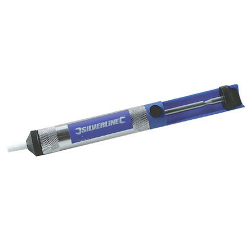
Also, I have a little experience with soldering but only with wires and not with pcb board. I have this silverline solder sucker but it's really not working well, doesn't seem to suck anything:
31MJPFsjZYL.jpg

- Any recommended solder sucker I should buy?

I'm using for now this cheap 60/40 solder reel: http://www.ebay.co.uk/itm/SILVERLINE-SOLDER-100G-ROLL-AS15-/190573444974?pt=UK_BOI_Materials_Supplies_Electrical_ET&hash=item2c5f0fff6e#ht_817wt_989
Is it ok?

And also, where can I buy mosfet with 100V cap as I'm using 72V battery?


Thanks a lot guys, that's really helpful for little newbie!
 
the solder suckers get plugged up and you have to clean out the clogs of solder in it to make it work.

first find out about the 5V and then we can test the halls, if they work you can to see if it will toggle the microprocessor.

leave the phase wires disconnected.
 
cwah said:
Also, I have a little experience with soldering but only with wires and not with pcb board. I have this silverline solder sucker but it's really not working well, doesn't seem to suck anything:
31MJPFsjZYL.jpg

- Any recommended solder sucker I should buy?


Thanks a lot guys, that's really helpful for little newbie!
I never use a solder sucker to remove components. I melt the solder around the component and then I tap the board on the bench and all the solder jumps off. You have to be quick and it takes a bit of practice, but once the technique is mastered, it's quicker and easier than a sucker. If a tiny bit of solder remains and holds the component and there's not enouh to melt, add a bit more solder before tapping. To remove big lumps of solder, turn the pcb upside down and work from underneath. The solder will melt onto the iron, and you then shake it off - no need for a wick.
 
cwah said:
knoxie said:
You will have caused more damage than its worth messing about with, chalk it down to bad luck and make sure that you dont do it again, I use anderson connectors which are keyed so that it is impossible to make this mistake, even when drunk (ahem and yes I have also done it too, so no shame :p ) but I have never blown anything up, I have fallen off after a couple of drinks though so its not to be advised and I dont do it any more.

Oh and before anyone flames me for Drink riding I only did it a few times and it wasnt on a public highway.

Just order another controller cwah and make sure you don't do it by changing the power plugs to anything that can not be connected the wrong way around, feel sorry for you dude as you have only just got this running too! good luck and if you need any more help just ask.

This is the second time I blow my stuff via reverse polarity. I really have to do something to prevent that. What's the best source to get anderson connectors in the UK? It seems so expensive! And I probably need good fuse too. Where do you buy it as you also seems to be located in the UK?

What ever the cost of Anderson's, you've far exceeded that with the controller costs.
 
dnmun said:
the solder suckers get plugged up and you have to clean out the clogs of solder in it to make it work.

first find out about the 5V and then we can test the halls, if they work you can to see if it will toggle the microprocessor.

leave the phase wires disconnected.

I've tried to measure the 5V rail between the red and black wire behind the pcb:
rail_voltage.jpg


I have 4.94V directly next to the rail and 4.39V on the hall sensor. All halls give the same voltage.

Not sure what it means and how to toggle the microprocessor.
 
Back
Top