Cycle Analyst V3 preview and first beta release

I notice that your list of chemistry selections doesn't include Li-NMC batteries (also known as NCM), which are new. They have higher energy density than LiFePO4, a little less cycle lifespan, but good safety. They are lighter weight for the same energy capacity. The all-electric car industry is moving to NCM for the next generation of electric (not hybrid) cars because they can increase the range in the same volume or weight compared with current technology.

Will V.3 include a selection for NMC?
 
overbyte said:
Will V.3 include a selection for NMC?

If there is a new battery chemistry that is both materially different in discharge curve to one of the existing lithium chemistries and is also readily available for ebike / EV enthusiasts, then for sure we'd do a characterization and eventually include it as a new option in one of the firmware updates. If someone can post here or send a link to an actual discharge curve of a Li-NMC pack of known internal resistance then I'd be able to at least point out which of the other chemistries is the closest match.

The reality is that even among the same nominal chemistry, every manufacturer's cells have a slightly different look to their discharge curve, so just selecting the chemistry isn't an exact thing. But so long as the look up table is within ~10% the battery fuel gauge indicator behaves perfectly fine and you'd never notice the difference between that at 1%.

-Justin
 
At least for the EIG cells, there is a spec that should help:
http://www.eigbattery.com/eng/product/C020.pdf
I think it has all the info you need for their versino of NMC.
 
Before I place my order for the beta v3, will the USB-TTL cable for Infineon controllers with the 6 pin connector (from Cellman) work for reflashing or do I have to buy another cable as well?
 
Architectonic said:
Before I place my order for the beta v3, will the USB-TTL cable for Infineon controllers with the 6 pin connector (from Cellman) work for reflashing or do I have to buy another cable as well?

http://www.endless-sphere.com/forums/viewtopic.php?f=4&t=37964&p=564885#p564885
 
Hi Justin;

I installed the new software. There seems to be an issue with the current readings being twice as high as expected. I use a 5.0 mohm shunt and only by setting the value to 9+ do I get close to the proper value. Rshunt is set correctly..

If your taking votes mines for putting the leading zeros back in. Too confusing and it seemed like you could have a blank spot if you dont set a number something like 12_45 etc. maybe left justified or something but for now confusing to know what column your in and how many places there are. I also like having a zero in front of the decimal.

I also noticed that in the real time screen the lowercase a becomes upper case, momentarily when you release the throttle while in current mode. Sort of seems logical. I have all limiting disabled currently.
 
Hello Justin

Just want to tell you that this is a piece of art. I just let my little brother( 12 years old) try my bike with two turnigy 80-100 motors. Within a few seconds the bike was limited to 50A and the bike was easy to handle. I love the way it works, and all of its options. Thank you for making this gadget for us. The bike would be uncontrollable without it.
 
teklektik said:
Although space had to be released to implement this cool screen, I do miss the displaced Vaux display (which admittedly does not have a huge audience). I much prefer the new version with limit flags but if you can find a way to squeeze in Vaux somewhere in the future, it would be good :)
Justin-
I would like to suggest that the real time Vaux display be resurrected as part of the Setup section title as "Setup Cntrl Mode < 0.00V >" in a manner similar to the "Setup Throt In < 0.00V >" section title. This would retain the most of the utility of this less frequently used display without intruding on the real estate of the primary non-Setup screens. Since the bike (throttle) is inoperative in Setup mode, the display would be usable only for adjusting or verifying control voltages with a standing bike - but that would fulfill the primary need, making it a very minor downside. :)
 
Justin, sorry it's taken me so long to get back to you regarding build 16.

The speedo issue at poweron would appear from casual inspection to be solved, although I still have a very high value being stored in MaxS (390 at the moment.) I also noticed with some curiosity that after the reflash, Mi was the default unit in Speedo Setup rather than Km as it has been before.

A new issue has arisen which I'm at a loss to solve. When I run the throttle up to full and allow it to hit the current limit (set at 25A) I am experiencing a very prominent surging, accompanied by the displayed current oscillating wildly back and forth across the limit point.

I've heard of others having to trim the various gains to reduce this sort of behavior. I have never had to do this before, as the system has always been stable, and thus I have always left my gains at the default setting. As a result, I don't have a good grasp of how these variables work or how to optimize them. I tried turning Again down to 50 (from 150) and it didn't seem to make any difference.

When I am operating in Current Throttle mode (my normal mode of operation), this phenomenon occurs only when I have the throttle at maximum. If I operate at mid-throttle, the system is stable. I tried switching to Pass-Through Throttle mode, and this made the problem worse. At very low speeds, even moderate throttle settings drive the system to maximum current (this is typical behavior for this bike) and the same oscillation occurs.

None of the Limit Flags are set when this occurs, at least in Current Throttle mode (I didn't observe the Limit Flags when in Pass-Through mode.) I do see the A limit flicker when I am operating in Current Throttle at part-throttle and a point below the 25A limit, however I assume this to be normal as the system appears to be stable at that point.


I'll add that I do not seem to be experiencing the problem which lizardboy noted concerning incorrect current display. With Rshunt set at 1.00 (the correct value for my controller), my displayed realtime current readings seem correct, and at the end of my morning commute, my total Ah and computed Wh/mile values also match expected values based on past experience.
 
Justin, I have some further data which may explain the problem I'm having, and also seems curiously related to what lizardboy has described regarding his current readings being doubled.

Normally, when I do a Zero Calibration, I see something like the following:

L37tJ.jpg


That screenshot was taken on the 15b code. I don't know exactly what the two different numbers signify, but they're always close to one another, and somewhere in the general vicinity of 2.5 - 2.4V.


Now, I just did a Zero Cal in the 16 code, and I see the following:

8I3b2.jpg


What's up with that?

I'll bet you €1 that our problem lies in this neighborhood.
 
Just a note guys - Justin is on vacation right now so for the next week or two replies may be a little slower than usual.

We've also received our full order of Thun sensors now so for those looking to get up and running with one you can purchase through the CA3 page: http://www.ebikes.ca/store/store_CAV3.php
 
Joe Perez said:
Normally, when I do a Zero Calibration, I see something like the following: ...
I don't know exactly what the two different numbers signify, but they're always close to one another, and somewhere in the general vicinity of 2.5 - 2.4V.
Since Justin is away - I will hazard a guess that these are scaled shunt voltages. The one on the left should be the working 'Zero Amps' offset voltage (stored in eeprom) and the one on the right is the present 'live' shunt voltage. When you press 'Zero Amps', the stored value on the left is updated with the value on the right, setting the working offset to make the present shunt voltage equivalent to 0.00 Amps. This is the same mechanism used to normalize Trq -> Trq Offset.

Setup Trq Sensor ........ Live Data = < 4.46V >
  • Trq -> Trq Offset {2.49V 4.46}
    (Press/Hold to update eeprom offset voltage on left with current voltage on right - similar to Zero Amps)
However, it appears that only 1/2 the present 'live' shunt voltage was stored as the working offset voltage.

EDIT - Well - not the best guess :wink: - proper answer by Justin here.

Justin-
It seems a bit inconsistent that these voltages are only displayed after doing a Zero Amps (at least I assume that's when they pop up - I've never actually done one since my CA reads zero properly without coersion). I would expect them to be always be displayed as they are with Trq->TrqOffset .
 
This latest release adds some useful features. Thanks for improving the product over the years.

The cruise control on the Infineon controllers is a constant-voltage cruise control. This works fine when I'm riding alone, but when I'm riding with others it tries to maintain constant speed regardless of grade, applying more power as the grade gets steeper, and less power as the grade lessens. This creates a situation where I pull ahead on steeper up-grades and fall behind as the grade lessens (unless I increase the throttle setting).

It would be easier to ride with un-assisted riders if the cruise control could fix the power level of assist rather than attempt to fix the speed (by fixing the effective voltage).

I believe that the current-based throttle offered through the CycleAnalyst (CA) is a solution since for a given throttle setting it would maintain constant current (power) regardless of grade. This behavior emulates the human engine that is power limited. But if I ran my throttle through the CA I would still be using the controller's constant-voltage cruise control.

Is there any plan to offer a constant-current cruise control capability when running a current throttle through the CA, one that allows the operator to "dial in" a fixed power level of assist?
 
Hello,
First of all, congratulations for all the work done. I'm very interested in this V3 especially by the throttle overriding features. I own a Magic Pie. Is it possible to buy this Beta V3 with a SA shunt? Or would I have to make it myself?

I have another question, about feature: is it (or would it) possible to activate the Regen via the PAS going backward (maybe half a round)?
 
Luge_a_foin said:
First of all, congratulations for all the work done. I'm very interested in this V3 especially by the throttle overriding features. I own a Magic Pie. Is it possible to buy this Beta V3 with a SA shunt? Or would I have to make it myself?
This does not appear to be a listed option yet, but I would guess they will at least sell you the required shunt dongle separately for you to solder into place or better yet, convert one one-off for you and calibrate the Rshunt value. Best to contact Grin Tech directly instead of going thru the forum.

If you get the standard dongle separately, you can hook it up by removing the CA-DP cable, ('Controller' JST-6, first one in this table) and hooking up the 4 conductor shunt cable color-for-color with the indicated pads previously used for pins 1-4. If you do this yourself you will need to calibrate the CA for the specific shunt. A quick Google search (type: site:endless-sphere.com calibrate CA shunt) turns up this post with links to instructions to two such procedures. This complete cable replacement would be usable for the newer V3 strategy where the CA supplies the throttle, not the legacy 'throttle override' approach, since you will be losing the throttle override pin (6) from the CA-DP cable.

I upgraded my existing CA-SA v2.23 with a v3 and so got the SA shunt by inheritance - works great. :D
 
Not sure if this has been discussed but I was wondering if it would possible to control the ebrakes with CA V3 but using a legacy throttle. I have my throttle wired directly to controller at the moment and I was wondering if it is possible to wire the ebrakes into the CA V3 instead of the controller. This would save some wires going to controller and a cleaner install. I'm not sure if the CA V3 can handle this since I have the throttle features disabled. I tested my legacy throttle and the ebrakes by hooking up an ebrake lever to the CA V3 and it did cut power to the motor. Is there something I could do other than wiring both the throttle and ebrakes directly to the CA V3?
 
Degull said:
I tested my legacy throttle and the ebrakes by hooking up an ebrake lever to the CA V3 and it did cut power to the motor. Is there something I could do other than wiring both the throttle and ebrakes directly to the CA V3?
It sounds like the test you performed successfully is exactly what you want... yes?

It seems that when the ebrake is attached to the CA and is applied, To (Throttle Out) is forced to ThrO->MinOutput.
  • In the new v3 mode with the throttle connected to the CA, To drives the controller throttle input and so will directly stop the motor.
  • In legacy mode, To appears as a throttle override to the controller and will override the operator throttle connected to the controller, indirectly stopping the motor.
This should work in either mode without an ebrake->controller connection.

As a possible downside, if your controller is programmed/jumpered for regen when ebraking, that functionality will be lost if the ebrake is fed to the CA. If this doesn't apply to your configuration, then it looks like you could save that extra ebrake wire running back to the controller :) .
 
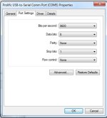
I have a Lyen USB TTL programmer with the Prolific PL2303 chipset.
I have setup the interface for the CA with an audio jack, and the communication seems very hit and miss. When I Detect Device It reads the CA & revision some times on power up.
I tryed flashing once after detecting the CA, but it failed.
I am using W7 64bit (just encase that is an issue) I can program my controller without problems.

Are there any port settings for the RS232 that may be causing bad communications.
Here are my current settings.

TTL.jpg

Cruzxia
 
teklektik said:
Degull said:
I tested my legacy throttle and the ebrakes by hooking up an ebrake lever to the CA V3 and it did cut power to the motor. Is there something I could do other than wiring both the throttle and ebrakes directly to the CA V3?
It sounds like the test you performed successfully is exactly what you want... yes?

Sorry that was a typo. I meant, by hooking up an ebrake lever to the CA V3 it did not cut power to the motor. In a haste to get outside this afternoon I did not proof read my own post :roll: .

teklektik said:
Degull said:
It seems that when the ebrake is attached to the CA and is applied, To (Throttle Out) is forced to ThrO->MinOutput.
  • In the new v3 mode with the throttle connected to the CA, To drives the controller throttle input and so will directly stop the motor.
  • In legacy mode, To appears as a throttle override to the controller and will override the operator throttle connected to the controller, indirectly stopping the motor.
This should work in either mode without an ebrake->controller connection.

As a possible downside, if your controller is programmed/jumpered for regen when ebraking, that functionality will be lost if the ebrake is fed to the CA. If this doesn't apply to your configuration, then it looks like you could save that extra ebrake wire running back to the controller :) .

Going to look over all my connections and test it again.
 
cruzxia;

I use the same programmer from lyen with those settings exactly. Works great for me It's all shrink wrapped up right now so I'll have to find the notes I made of the wiring to help you. I had trouble getting it to work at first. I tried a couple of different wirings. Make sure you follow the instructions exactly! Initially I wasn't turning things on in the correct order and my detection was very hit and miss. It'll show as com5 but I'm sure you know that. your not tied through the switch or anything?

I'll look for my notes I'm sure they were right here... somewhere
 
Lizardboy

That would be great if you can advise how you set it up.
FYI I have the switch on, as it provides the ground reference.
 
Back
Top