You are using an out of date browser. It may not display this or other websites correctly.
You should upgrade or use an alternative browser.
You should upgrade or use an alternative browser.
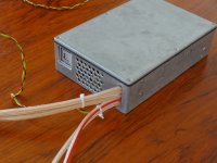
The big Lebowski controller
- Thread starter Lebowski
- Start date
Kingfish
100 MW
Beauty!
Does it come in Black? Need a whisper fan?
Lead time?
<snicker> KF
Does it come in Black? Need a whisper fan?
Lead time?
<snicker> KF
Philistine
100 kW
- Joined
- Aug 15, 2010
- Messages
- 1,736
Is it a device for measuring the physical weight of verbs and concepts?
If so, how much and when can I get one?
EDIT: I don't care about colour, but mine needs a splash guard.
If so, how much and when can I get one?
EDIT: I don't care about colour, but mine needs a splash guard.
Lebowski
10 MW
Philistine said:Is it a device for measuring the physical weight of verbs and concepts?
If so, how much and when can I get one?
EDIT: I don't care about colour, but mine needs a splash guard.
hahahahaha
I'll post more pictures tomorrow when I have the time
electronic panty remover ?
The fingers
10 TW
Looks bullet proof. 
Lebowski
10 MW
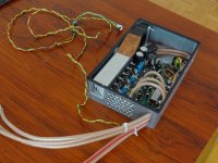
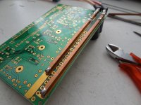
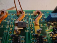
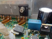
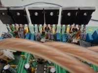
Finally added lots of pictures to the first post 
hjns
100 kW
To me it looks just like a big noisy paperweight..... 
Bas, you really should get it patented!
Bas, you really should get it patented!
Philistine
100 kW
- Joined
- Aug 15, 2010
- Messages
- 1,736
Mr Dude (Sir),
Can you throw on some funky Bass riffs and funky wa wa guitair on in the background, put on a Barry White voice (I can do that part in my head if you like), and give some more details on specs and what kind of power it can take, and is it avaialable for sale in the future?
Easy for you to make the comments about tools, I couldn't make anything look that tight and nice even if it did nothing functionally. I can make zip ties look like they were attached without care.
Lebowski
10 MW
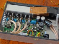
To be honest I got no clue about how much power it can take. It uses 150V FETs and has 150A current
sensors (150A amplitude, not RMS). But long before 150A the FETs will burn out due to insufficient
cooling, it'll be a case of slowly upping the amps and see how hot it gets. Member 'hjns' has kindly
offered me to try it out on his Cromotor equipped bike, with 20s lipo (maybe 30s). I'm expecting this
to be a test until it blows up (be easy to fix though as I designed and built it).
I don't plan to sell controllers like this as it took me more than a month of hobbytime to build, there's
lots of work in the cooling hardware and box. The intention is to sell PCB's and the main IC's so people
can colder the PCB's themselves and build whatever box / cooling system they want. Also, mine is outfitted
with 150V FET's, you can just as easely (with the same PCB etc) use 100V FETs with a lower on-resistance
to tune it more towards whatever motor you have.
hjns
100 kW
what about 35S (147V HOC) ? 


Philistine
100 kW
- Joined
- Aug 15, 2010
- Messages
- 1,736
I don't plan to sell controllers like this as it took me more than a month of hobbytime to build, there's
lots of work in the cooling hardware and box. The intention is to sell PCB's and the main IC's so people
can colder the PCB's themselves and build whatever box / cooling system they want. Also, mine is outfitted
with 150V FET's, you can just as easely (with the same PCB etc) use 100V FETs with a lower on-resistance
to tune it more towards whatever motor you have.
Respect, I was kind of fantasising in asking if it would be for sale. The way you did the Fets looks so convenient to me, even a monkey like me could solder in replacements when set up like that. Congrats on designing and building it.
salty9
1 kW
Had you considered using a coiled aluminum sheet for the interior of your heat sink? You should be able to get a larger surface area and decreased mass.
John in CR
100 TW
Beautiful! I feel the need to now call you Sir Lebowski unless you prefer simply Mister Lebowski. With a board and a shopping list is it realistic for a caveman solder slinger to pull it off, or can I just take a box of stuff and the schematic to a local electronics repair shop for assembly? Yes, things actually get fixed here instead of dropped at the curb for recycling, so a pro solder slinger is easy to find.
I can only imagine how well and how efficient 2 of these would drive my 6 phase motors, because I know yours doesn't have this confounding jerk of a start I still suffer with.
John
I can only imagine how well and how efficient 2 of these would drive my 6 phase motors, because I know yours doesn't have this confounding jerk of a start I still suffer with.
John
TylerDurden
100 GW
Dude! 
Kingfish
100 MW
No man, he is The Dude! Nothing less will do.
Or perhaps...
[youtube]Be7Og9Gc_KY[/youtube]
So freakin' awesome! What else can it do aside from going forward fast?
Cheers! KF
Or perhaps...
The Dude said:Let me explain something to you. Um, I am not "Mr. Lebowski". You're Mr. Lebowski. I'm the Dude. So that's what you call me. You know, that or, uh, His Dudeness, or uh, Duder, or El Duderino if you're not into the whole brevity thing.
[youtube]Be7Og9Gc_KY[/youtube]
So freakin' awesome! What else can it do aside from going forward fast?
Cheers! KF
John in CR
100 TW
I stand corrected, The Dude 
cal3thousand
10 MW
The dude abides!
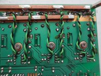
Woah, that is one beautiful thing. Especially after looking at the internals of my crappy chinese knock off controller and the build quality. Those copper bars are solid! Love it.
Woah, that is one beautiful thing. Especially after looking at the internals of my crappy chinese knock off controller and the build quality. Those copper bars are solid! Love it.
Lebowski
10 MW
circuit said:Why are there 3 current sensors instead of 2?
The controller looks OK as a testing platform, but I just can't see a product any time soon. I really want to, but can't.
Well, it's not my intention to build and sell complete controllers, at the moment I'm just in this for the
hobby. What I can sell is PCB's and programmed IC's so that people can build their own controllers. What John suggests
is very well possible. Or maybe someone who likes soldering and building can build and sell controllers based
on my IC's and PCB. My intention and interest is to develop my controller IC further and to include power
startup with full torque at motor standstill, without hall sensors. My interest is in the algorithm running on the
MCU, less in soldering everything together and building controller boxes. I build the box of the first post because
I want to try out my algorithm on a powerful motor, and as a demonstrator to show that the algorithm works.
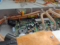
About the current sensors, theoretically 2 sensors (lets say Ia and Ib) are enough because the current in the 3rd motor wire (Ic)
can be calculated with
Ic = - Ia - Ib
But typically the sensors pick up noise from their supplies etc, a noise which can be in a large part common in all sensors.
Ia = Ia_wanted + I_noise
Ib = Ib_wanted + I_noise
then
Ic = - Ia_wanted - Ib_wanted - 2 * I_noise
So with 2 sensors all the noise gets assigned to the 3rd motor wire.
With 3 sensors though the noise part common to all sensors (the I_noise) can simply be filtered out by the
algorithm running on the MCU....
Jeremy Harris
100 MW
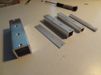
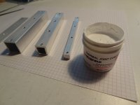
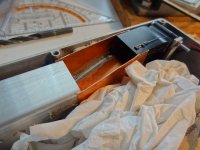
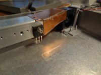
Looks very good to me. I particularly like the cooling arrangement, very neat. My guess is it took longer to build that bit than assemble the rest of the controller!
I always find building the hardware of any project like this the hard part, it always seems to take more effort to get the physical layout neat and the housing OK than it does to do the electronic stuff.
I always find building the hardware of any project like this the hard part, it always seems to take more effort to get the physical layout neat and the housing OK than it does to do the electronic stuff.
drewjet
10 kW
Lebowski said:The finished controller. Unfortunately it does not have the impressive wiring spaghetti we're used to, two battery wires, three motor wires and (the thin wires) gnd, 5V and 2 throttle inputs.
So this will only run sensorless?
How well will it drive an RC motor? either Astro or 80/100.
Similar threads
- Replies
- 0
- Views
- 217
- Replies
- 0
- Views
- 521
- Replies
- 58
- Views
- 4,638


