Cycle Analyst V3 preview and first beta release

Well just to say that over the past few weeks we have finally got to the bottom of some of the issues that have been holding back release and further code development. The first and biggest one was the occasional 20-30 second freezup of the CA display that a few people like Tekletik and Cruzxia have mentioned, usually preceded immediately by very high glitch in the human watts number.

For some reason I had convinced myself that this was some mysterious and deep bug in the firmware, but it turns out to have been a hardware issue. At some point while testing different PAS sensors the internal pull-up resistor on the RPM input line was disabled, allowing this voltage to float. If someone didn't have a PAS sensor connected, then the floating voltage could gradually drift pass the logic threshold, and in a noisy environment it would then trigger a crazy large number of PAS sensor events to the CA, first resulting in large RPM and HWatts figures and in extreme cases eventually tying up the CA in an almost infinite sequence of interrupts.

If you short the PAS RPM input to Gnd then this never happens. In the current Beta19 firmware the internal pull-up to 5V is enabled so you can leave it disconnected without any worry.

My 'human power' graph has just started showing up on the display for some reason. It fluctuates from full to nothing every few seconds.

This is the same issue above. In a pinch you can put a jumper between pins 2 and 4 of the 5-pin PAS connector and will stay at 0, but best to reflash with the B19.
 
Can wait to get my hands on the CA V3 and Thun BB !

Great news that you are almost ready for the public FW.

Many thanks to everyone here who has contributed towards ironing out these bugs.

Jason
 
The 2nd item was that after resetting or power cycling the CA, the voltage display would sometimes jump between two different readings that were about 0.2V apart. It turns out that the trace with the scaled battery voltage weaves very close to the crystal oscillator and was picking up oscillator noise. The internal CPU clock runs at 4 times the oscillator frequency thanks to a phase locked loop, so depending on the exact crystal startup sequence the beginning of each ADC sample could alias with a different part of the clock noise, which explains why the display would be steady but would randomly change state after a power cycle, reset, or other event that interrupts and restarts the oscillator and phase locked loop.

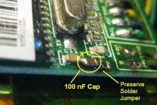
Unfortunately the only way to remedy this is with a hardware modification to the board. The easiest is to solder a 10-100nF capacitor to the signal line, as depicted in the picture here:
100nF_CA3_Cap.jpg

The capacitor can solder between the top of C11 (gnd) and the bottom of the solder jumper which has the scaled pack voltage signal. It's important to be sure that the solder on the jumper still bridges the lower and middle pads. We can send a handful of 100nF 0805 surface mount caps to anyone with a V3 CA who would like to eliminate this issue, just contact by email with your mailing address and we'll have them fired off.

All of our existing supply of boards will be modified with this capacitor add-on, and we will change the board layout for the next batch to avoid this issue. That said, in practice, the 0.2V variation in voltage isn't of any material consequence, since it's less than 0.5% of the typical ebike battery voltage and within the 1% expected CA accuracy. So if you have a V3 CA beta device, I wouldn't generally worry about this unless you have a situation where a difference of 0.2V on the overall pack is important.

-Justin
 
naix said:
What is a recommended setup for giving a quick response to start dash?

For that, you will want to set the "Start Delay" to a high number, like 60 or so. You should also choose a PAS sensor that has many poles. I've seen PAS rings with just 4-5 magnets, and others that have more like 12. The more magnets or pulses per wheel rotation, the faster the CA can react to your start of pedaling. The torque assist mode also still requires that you are pedaling before the proportional assist will kick in (otherwise for instance, you could just stand on the pedals and generate a very large torque signal without doing any work).

-Justin
 
Diamondback said:
Can wait to get my hands on the CA V3 and Thun BB !
Great news that you are almost ready for the public FW.

So it's actually getting very very close now and I would like repeat Jason's thank you to all the beta users who have helped to identify and sort a number of glitches so far. Having a lot of hands and eyes really helps immensely.

I've finally got around to publishing a decent amount of documentation of the V3 CA on our website too, including all the connector pinout and wiring info as well as an explanation of every item in the setup menu.

http://www.ebikes.ca/store/store_CAV3.php

On that website is also a link to the Beta19 firmware that solves the crazy Human Watts and occasional crashing bug. Also, be sure to download the latest firmware utility program from there too, as the earlier one I had posted here did not support firmware updates that left the calibration data alone.

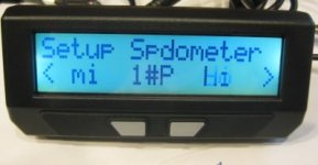
One of the other additions to the B19 code is that I now have a 'preview' display on every screen in the setup menu. For instance, in the "Setup Spdometer" display, you can see your unit selection, the number of poles, and a real-time display of whether the speedo signal is currently high or low. That way it's easy to diagnose if a speedometer sensor is picking up and it simplifies figuring out the number of poles in a motor by rotating one full revolution and counting the number of Hi-Lo transitions.
Setp_Spdometer.jpg

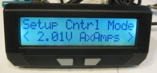
Similarly, you can see what your auxiliary potentiometer voltage is at and whether it is set up for amps limiting, speed limiting, watts limiting etc.
Setup_CntrlMode.jpg

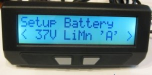
And the "Setup Battery" preview shows whether you have pack 'A' or 'B' selected and displays it as a chemistry and nominal voltage (inferred from the series cell count):
Setup_battery.jpg

There are a few more display refinements being worked on in the Beta20 code. But if a week runs by with nobody reporting any issues in the B19 firmware then I think we'd be basically ready to go live. Then it will be time to open the champagne bottle and celebrate!
 
Setup Summary for CA v3B19

The setting summary for the newer v3B20 release is available here.
The setting summary for the previous v3B16/v3B17 releases are available here.
Unofficial basic setup notes are available here.

Please see the Grin Tech Site for a detailed explanation of Setup Parameters.

Printable version: View attachment CA_v3B19_ConfigSettings.zip
 
The thread is extremely long.
Is there a way to use the cycle analyst V3 to turn a rc controller system into a current based throttle instead of speed based?
 
You may wish to look at the RC-CA version thread linked in the very first post of this thread. here is the link again:
http://endless-sphere.com/forums/viewtopic.php?f=28&t=29846
 
I know there are some readers who have been sitting on the fence about the V3, so here's a quick knee-jerk evaluation of v3B19 (short form: the wait is over! :D )

Using the new Firmware Flash Utility from the CAV3 page of the Grin Tech site, I flashed v3B19, trying both the plain vanilla and NoCal versions. As Justin promised, the NoCal version preserved the settings in the Setup 'Calibration' section. Nice.

My bike is as described in my signature below and has no PAS or temp measurement equipment so I cannot speak to those features. The CA is configured according to the Unofficial Setup Notes - here's my exact settings:


In broad strokes my CA is set up for Power Throttle (new feature!), power limiting on CNTL input driven by LMH switch, and Plim->MaxPower=3300W. Because I have BMC gear motors, I'm running a slow ThrO->UpRamp=32 to save the clutches and no down ramp at all (ThrO->DownRamp=999).

Setup works very nicely with no glitches or display artifacts at all - not much to say - it's final production quality. The live data voltage and speedometer displays make a review of equipment health quick and effortless.

I took the bike on a no-pedal 30 mile run today and the CA worked flawlessly. There is no surging or cutouts and the Human Power display behaved itself (I have no PAS so 'behaved' means it stayed at zero :) ). There were absolutely no issues - everything was smooth as silk at all LMH settings from 450W to 3300W. The closed loop Power Throttle (similar to Current Throttle) worked smoothly with nicely refined control from barely rolling to WOT both on the flat and up hills.

You can use either Current or Power limiting for throttle and CNTL features, but since I have voltage to burn at 66v, I use the Power settings. The result is that the bike runs the same at the end of ride at 60v with 80% DOD as it does hot off the charger at 73v. Very nice. (There is also a closed loop Speed Limiting option for throttle/CNTL but I have not tried that mode under v3B19.)

Justin has promised some refinements/features for v3B20, but I find v3B19 to be bike-ready. I haven't flogged the daylights out of it, but the anomalous behaviors of the past appear to have been addressed and the current state of the firmware is nicely polished.

My bike has two torquey gear motors running above the recommended max of 60v which gives the bike a twitchy and unmanageable throttle curve and too much torque for the clutches to endure. Adding the V3 gives me smooth getaways, refined throttle at all speeds, and provides an LHM switch not available on my controllers - it completely transforms the riding experience - hard to believe it's the same bike. This is not the purchase for someone who just wants an Ah meter, it's for folks who want their unruly throttle, controller, and motor to make nice and play together. If you have a MAC or BMC, buy a V3 instead of a replacement gear cluster...

I'm sure this post sounds gushy and some small issues may turn up, but v3B19 is a giant step forward and really delivers. :mrgreen:
 
Don't mince words. Do you like it or not?

:)
 
teklektik said:
In broad strokes my CA is set up for Power Throttle (new feature!), power limiting on CNTL input driven by LMH switch, and Plim->MaxPower=3300W. Because I have BMC gear motors, I'm running a slow ThrO->UpRamp=32 to save the clutches and no down ramp at all (ThrO->DownRamp=999).

Power Throttle sounds like a great new feature. Can you tell us if there is a cruise control capability when using the CA throttle in each of its modes (power, current, or voltage)?

What is an "LMH switch"?

Thanks.
 
justin_le said:
Also, be sure to download the latest firmware utility program from there too, as the earlier one I had posted here did not support firmware updates that left the calibration data alone.
This makes me exceedingly happy. :mrgreen:


rscamp said:
Don't mince words. Do you like it or not?
I'll provide a non-minced summary.

I've been using the CA3 for a few months now, and it's just a great box, period. The closed-loop current throttle mode alone is worth the purchase price. I can't imagine a better device to have hanging on my handlebars.
 
Yet again this amazing site and people come through in helping anyone doing anything EV and them some... :mrgreen:
 
mrbill said:
Can you tell us if there is a cruise control capability when using the CA throttle in each of its modes (power, current, or voltage)?
Presently no. See this post for planned cruise control capability.

mrbill said:
What is an "LMH switch"?
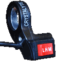
This is a (handlebar) 'Low/Medium/High' switch typically supported by controllers to scale the max throttle on-the-fly to selectable percentages of the maximum configured Amps (e.g. 20%, 50%, 100%). This makes higher powered bikes more controllable for protracted lower speed operation like diddling along on a bike path. Here I was using the term generically to indicate similar functionality that can be obtained using the V3.

LHM-switch.png
 
teklektik said:
I'm sure this post sounds gushy and some small issues may turn up, but v3B19 is a giant step forward and really delivers. :mrgreen:

I swear that I don't pay teklektik to say that! But I would like to hear back especially from other people who have had some issues or glitches with their beta device so far, as to how it behaves with the B19 firmware. So if you can get a chance to install and try it out in the coming week that'd be great. The speed limiting really can be dialed in to work well, so those with a bit of familiarity with PID controllers I'd encourage playing around to find the gain values that best stabilize your setup in speed limit mode and post them here.

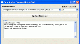
Attached as well is an even more refined firmware updater utility. There are still a few more tweaks before we make it official but it's now just a single button press to reflash a unit and gives better status updates on the progress. It will default to selecting the highest value COM port which is normally what gets assigned to the USB->TTL adapter when it is plugged in, and if you move the firmware .hex files to the same directory where the program is unpacked then it will automatically list them in the drop-down.

Flash_Updater.gif

-Justin
 

Attachments

  • CAFUT-SE.zip
    5.1 MB · Views: 182
teklektik said:
I know there are some readers who have been sitting on the fence about the V3, so here's a quick knee-jerk evaluation of v3B19 (short form: the wait is over! :D )

....
I'm sure this post sounds gushy and some small issues may turn up, but v3B19 is a giant step forward and really delivers. :mrgreen:

Very nice review. I will flash to B19 once I get back home from my holiday next week, and post the results with my cromotor at 20S lipo, power throttle, and temp limit.
 
justin_le said:
I swear that I don't pay teklektik to say that!
What!?? So the check is no good? :mrgreen:

Seriously though, you have only to flash the initial release and compare it to the current release to see the change in the complexion of the unit over these many months - it's like a different product. Looking at the recent posts about the thread length (40+ pages) and knowing that the product seemed suspended with show-stopper problems and many cautionary posts and issues, it seemed time to reset expectations.

Stepping back and looking at the persistent critical issues, their most distressing characteristic (although perhaps not well expressed in the posts) has been that they could not be reproduced at Grin Tech. What sets v3B19 apart is that the problems were finally able to be reliably reproduced in the lab so development could move forward and specific revisions could be introduced to address them. This is huge.

Again - although the post was a bit enthusiastic and did not have the benefit of extensive testing, after months of beta testing, there is nothing like a great ride on sunny Autumn day with a V3 that works out-of-box to make it all seem Good... :mrgreen:
 
Throttle ramping and min/max voltage range scaling to match throttle and controller voltage ranges can improve operation in fairly obvious ways, but it might be useful to take a quick 30,000ft view of how the various CA throttle modes can give more refined operator control.

Open Loop Throttle

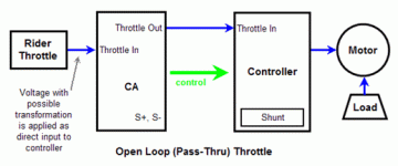
The illustration below shows the CA in Pass-thru mode - similar in concept to directly connecting the throttle to the controller except that the V3 may apply some Vin-to-Vout scaling and Vout ramping. This is an open loop control configuration where the control voltage is applied to the controller and transformed by the controller/motor curves to directly affect the final motor output. For controllers/motors with curves possessing steep steps in input/output transformation, a small rider throttle change can affect a large alteration in motor power.
openloopthrottle.gif
Closed Loop Throttle

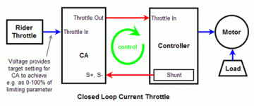
This second illustration shows the CA in Current Throttle mode. This is a closed loop control configuration where the rider throttle is not passed through to the controller but rather sets a target output for the CA to achieve - the CA provides the controller throttle and receives feedback from the shunt to determine how well it has done in achieving that target. It then adjusts the controller throttle, etc in a closed loop to cause the output to automagically track the desired rider throttle input. Because the load is reflected through the motor back to the shunt, the CA will maintain the target current regardless of changes in terrain.

In this mode any unpleasant non-linearities in the controller/motor curves are of little consequence as the CA can rapidly and precisely adjust to get the desired output - this task is no longer the responsibility of the rider. Some controller/motor curves may have strongly non-linear characteristics that require small adjustments to the CA control mechanism, however these are simple gain adjustments to prevent 'hunting' or oscillation, not detailed configuration of input/output throttle curve mapping.
closedloopcurrentthrottle.gif
In this Current Throttle example, if Plim->MaxCurrent is set to 50A then WOT is 50A. Assuming the rider throttle is more or less linear, adjusting the throttle to 10% rotation yields a predictable controller output of 10% of 50A or 5A.

The closed loop illustration can be redrawn for Power or Speed Throttle with appropriate alterations to the source of the feedback. The table below shows the available throttle types - all but Pass-thru are closed loop. The columns show the physical metric the CA uses for feedback and the relevant parameters for each type of operation. To get the smoothest and most consistent operation it may be best to set the 'other' limits as loosely as possible (i.e. as true maximum safety limits) so only the single thottle limiting parameter is generally in play.

It is important to note that the CA Speed Throttle is completely different than the Infineon throttle logic which is often misnamed as a 'speed throttle'. The CA Speed Throttle is a true closed loop control system that measures the bike speed and corrects for variations. In contrast, the Infineon throttle uses open loop control to vary phase PWM duty cycle according to the input throttle voltage without regard for directly measured bike or motor speed; this results in varying speed with load and terrain.

cav3ThrottleModeSummary.gif
Aux POT (Vpot) Input

The Aux POT input (aka Vaux, Vpot) operates in a fashion similar to the rider throttle (ThI) in that an applied voltage limits the associated parameter to some percentage of the configured maximum value. The CA PCB provides three pads for Aux POT: +5v, Gnd, and POT. This makes it straightforward to connect a potentiometer that will provide 0-5v to the POT input. For example, if Plim->MaxCurrent=60A, Aux->AuxFunct=AmpsLim, Vaux input voltage (min,max) is (0v,5v), and the POT input is adjusted to 2.5v (50% of 5v), then the controller will be limited to 50% of 60A or 30A. In lieu of a potentiometer, a few resistors/trimpots and an on-off-on SPDT switch can be used to provide the familiar LMH switch functionality.

View attachment 2
Throttle Scaling

By setting both Aux->AuxFunct and the ThrI->CntrlMode to be associated with the same limiting parameter, the throttle will scale against the output of the Aux POT feature instead of the Limiting Parameter directly. This is shown in the last column of the table above.

For example, assuming Vbatt = 60v and Plim->MaxCurrent = 50A then Plim->MaxPower = 3000W . Because of Vbatt, the respective max current/power limits should have essentially identical effects, but the following example shows this may not be the case.

  • The question:
    What are the throttle response curves for an Aux POT 3-position LMH switch with values of 20%, 70%, and 100%?
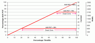
Case A: DIFFERENT LIMIT PARAMETERS - The throttle limits current and Aux POT limits power. As shown below, when set to different Limiting Parameters, the throttle and Aux POT limits operate independently causing the throttle to try to follow the same slope curve ( 0 to Plim->MaxCurrent = 50A) in each switch setting. However, where Aux POT is less than 100%, the AUX Pot limit appears as a limiting ceiling where advancing the throttle has no effect. In these cases the diagonal curve flattens for the remainder of the throttle range of motion yielding a 'dead zone' in the same manner as legacy CA V2 limiting.
CaV3ThrottleAuxPotLimit-diff.gif
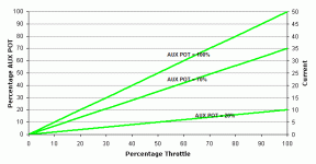
Case B: IDENTICAL LIMIT PARAMETERS - Both the throttle and Aux POT limit current. The throttle is not limited by Plim->MaxCurrent but rather by (Plim->MaxCurrent) x (percentage of AuxPOT). As shown below this has the effect of scaling the entire throttle range of motion from 0 to Aux POT (switch) limit, eliminating dead zones. The WOT current limits are identical to those of Case A (10A, 35A, 50A), however, the throttle curves for Aux POT less than 100% are dramatically different, showing a uniform linear relationship between throttle and current with no dead zones. This scaling is similar to that of the Infineon controller 3-speed switch.
CaV3ThrottleAuxPotLimit-same.gif
In Case B, the combined effects of the CA closed loop logic and the expanded range of motion make small speed adjustments at low power very much less challenging than in the open loop direct connect approach.
 
hillzofvalp said:
That is so useful. Thanks for the informative posts. :D very close to pulling the trigger.


+ 1 for me too.

i intend to run the Thun BB and use a pot to set the assist level based upon the torque sensor in the BB.

i will leave the throttle connected also, but i am going to disable it (via Strt speed) until 3-4km/h.
with that set-up and some tweaks of the settings, i should have a system that behaves much like
the bionx does, but has more power (around 960W max) and i wont be locked into expensive proprietary
batteries and controllers.

i am just waiting until the beta is finished.

many many thanks to all who have contributed to testing and ironing out all of the little bugs in the FW.

Jason.
 
Hi Teklektik,

Thanks again for the very comprehensive overview. I really think that this thread is like a super justification for you to be the main CAv3 consultant in the world.

Therefore, a small question from an electronics-noob, who can handle a soldering iron, but has no clue about circuits. What kind of pots and resistors and in what configuration would you recommend to adjust a conventional 3-way switch to work with the CAv3?

My 3-way switch is actually a ¦ A-0 ¦ A-B ¦ A-C ¦ switch, and works with my infineon based controllers. From what I see on the forums and the different e-bike shops, this is a very common switch.
T-3Switch.jpg


I was thinking that the ¦ A-0 ¦ setting would be equivalent to setting a pot meter to infinitely high resistance.
The A-B could be connected to a variable pot providing around 50% resistance.
The A-C could be connected to a variable pot providing around 0% resistance, or just remove the pot altogether.

Is this understanding correct? And in order to make this happen, what kind of pots should I use?
 
Thanks for the enthusiastically kind words - there must be something in the air these last few days that's making us post all gushy-like :D.

Seriously though, I've been meaning to post some CAv3 LMH switch details for some months now, but it got back-burnered... I will get a post up straightaway with a couple of ways to do this that will play nice with the A/D converter impedance and on-board regulator capacity.
 
hjns said:
My 3-way switch is actually a ¦ A-0 ¦ A-B ¦ A-C ¦ switch, and works with my infineon based controllers.
Hmm - perhaps you could verify my understanding of your switch operation. Conventional SPDT switches typically come in a center-OFF variety and are usually designated as on-off-on, however, it appears from your description that your switch is off-on-on.

(1) Can you please verify that the three switch positions have these make/break characteristics for connections (A,B,C):
  • (position I) no connections
    (position II) A to B; C not connected
    (position III) A to C; B not connected
(2) Which position do you want to be 'full power' or does it matter?

I ask because I purchased a similar-looking generic switch supposedly compatible with Crystalyte controllers and it is of the conventional on-off-on variety. I chugged out some simple dividers last summer that will configure such switches as either LMH or LHM and would like to see if one can be pressed into service for your switch without modification. If you are set up as I outlined above, it looks like the existing LHM divider might be directly usable giving you a setup where I=H, II=M, III=L (which might seem a little backwards, but it's all in the eye of the beholder :)...)
 
teklektik said:
hjns said:
My 3-way switch is actually a ¦ A-0 ¦ A-B ¦ A-C ¦ switch, and works with my infineon based controllers.
Hmm - perhaps you could verify my understanding of your switch operation. Conventional SPDT switches typically come in a center-OFF variety and are usually designated as on-off-on, however, it appears from your description that your switch is off-on-on.

(1) Can you please verify that the three switch positions have these make/break characteristics for connections (A,B,C):
  • (position I) no connections
    (position II) A to B; C not connected
    (position III) A to C; B not connected
(2) Which position do you want to be 'full power' or does it matter?

I ask because I purchased a similar-looking generic switch supposedly compatible with Crystalyte controllers and it is of the conventional on-off-on variety. I chugged out some simple dividers last summer that will configure such switches as either LMH or LHM and would like to see if one can be pressed into service for your switch without modification. If you are set up as I outlined above, it looks like the existing LHM divider might be directly usable giving you a setup where I=H, II=M, III=L (which might seem a little backwards, but it's all in the eye of the beholder :)...)

You are completely right. I didn't think it would matter. I have a 3-switch (I, II, III) with 3 wires (A, B, and C), with the following possibilities: I = A-B, II = Off, III = B-C.

I prefer position I to be the lowest power, and III to be the highest power. However, that is a nice-to-have. Then again, with variable pots on all three of them, one could set them up however you want, right? I guess the II position would be a challenge....
 
hjns said:
I have a 3-switch (I, II, III) with 3 wires (A, B, and C), with the following possibilities: I = A-B, II = Off, III = B-C.
I prefer position I to be the lowest power, and III to be the highest power.
Okay, this is good - it's a conventional on-off-on switch and it looks like you want a Low|Medium|High (LMH) configuration. There's not much to these and I don't really mind doing another but I'm happy to be able to skate with what is already in hand... :D
 
Back
Top