Shimano Deore XT brake lever switch with Hall effect sensor

avandalen

100 W
Joined
Oct 2, 2010
Messages
175
Location
Maastricht, The Netherlands
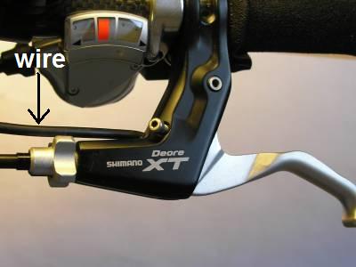
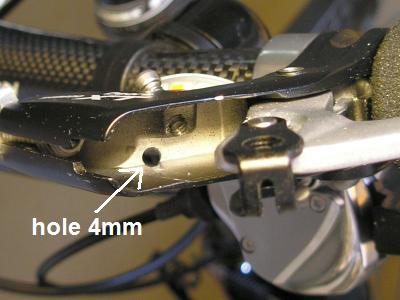
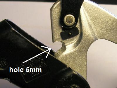
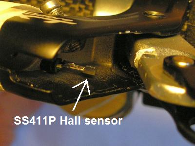
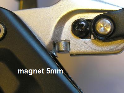
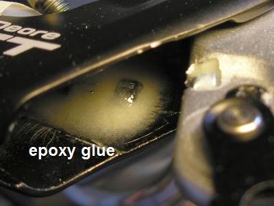
Here is a method to build a switch into a brake lever; the brake lever doesn't have to be replaced and no external switch is needed. I use Hall effect sensors as switch, because they are reliable, watertight, small, and inexpensive. Used is the SS411P, but almost every hall sensor may be used. The 5mm magnet comes from a PAS sensor magnet ring. As an example, the Shimano Deore XT brake lever is taken:

Brake-switch-00.jpg

Brake-switch-01.jpg

Brake-switch-02.jpg

Brake-switch-03.jpg

Brake-switch-04.jpg

Brake-switch-05.jpg


See more here:
http://www.avdweb.nl/solar-bike/mechanical-issues/brake-switch.html
 
That is clever and well engineered,avandalen! I may have brake cut offs for the first time in 10 years or so of E-bikes. How do you wire up the sensor since it has 3 legs and most e-brake controllers have only 2 wires?
Thanks
otherDoc
 
Many of the "infineon" or XieChang or other clone controllers actually have two different ebrake methods inside, a two-pad and a three-pad. I might ahve this backwards, but IIRC if you use EBS- and ground, you get a two-wire ebrake. If you use EBS+, 5V, and ground, you get a three-wire ebrake. It may also depend on the controller design/model, as there might be different names for the signals on some.
 
Thanks AW. I have an old "Infineon" on my trike and do want to do this mod. Maybe a reed switch instead of a Hall? Definitely 2 wire then. How would I know which wire goes where for the Hall sensor?
otherDoc
 
Depends on the sensor, but the pinout is on the spec sheet. here's the one from mouser for hte ss41:
http://sccatalog.honeywell.com/pdbdownload/images/ss40.series.chart.1.pdf
lower left corner of first page, shows +V on left pin, ground on middle pin, and output on right pin, if sensor is label side up and pins toward you.

As for which pins in the controller, that depends on the controller. You mihgt have to find your variation in one of the various mod threads and see what pin is used for the brake input for hall brakes, but it's probably EBS(something), and you can use any 5V and GND.
 
Thanks AW. That really helps.
otherDoc
 
Thank you for sharing this information!!!

And DX sells strong magents VERY cheap: http://dx.com/p/super-strong-rare-earth-re-magnets-8mm-20-pack-4248
 
amberwolf said:
Many of the "infineon" or XieChang or other clone controllers actually have two different ebrake methods inside, a two-pad and a three-pad. I might ahve this backwards, but IIRC if you use EBS- and ground, you get a two-wire ebrake. If you use EBS+, 5V, and ground, you get a three-wire ebrake. It may also depend on the controller design/model, as there might be different names for the signals on some.

What pin is EBS- ?
 
Open up your controller and take a peek.

It'll be marked as such if you have that function on there. If it's not marked that way you'll have to figure out which one it is, if it has one at all.
 
Those don't use hall sensors, they just short the two wires for their brake sensor. You'd have to make a circuit to power the hall from the throttle power and convert the hall output to whatever is needed to drive the MP input.
 
Failure mode of the brake switch should default so it kills system, also a diagnostic code would be helpful :p
 
I AM A NEWBIE,but would'nt it be easier to just lay off the throttle when braking???not sure I understand what this is for???
 
korpin said:
I AM A NEWBIE,but would'nt it be easier to just lay off the throttle when braking???not sure I understand what this is for???

There are several reasons why this might be a good idea for a bike.

1. Will shut off cruise control when braking.
2. Will shut off motor during panic stop when you might not let off throttle.
3. Will shut off motor in the event of wide open throttle failure.

I'm sure there are other reasons too.

Gary
 
maybe someone can help me. i try to build this myself.

connected 5v to the left pin, ground to the middle pin, and read voltage from the right pin.
hall sensor lying in front of me, printing on pin is readable, pins facing towards me. so this should be correct.
when i move a magnet near the hall sensor - i took one from a pas sensor - the following happens:

.) magnet facing in directiion 1 : voltage drops to 2mV. stays there when magnet is removed.
.) magnet turned 180°: voltage raises to 300mV. stays there when magnet is removed.

how is this ever gonna work? afaik hall sensors don't change their state until a magnetic field with reverse polarity is "applied".
so if the magnet is moved into the direction of the hall sensor, it switches to on/off - depending on the magnetic field, and stays in this state.
and i don't see a second magmnetic field being involved.
i don't see 5V at the sensor pin either, only 0.3V.

what am i doing wrong?
thanks
 
izeman said:
how is this ever gonna work? afaik hall sensors don't change their state until a magnetic field with reverse polarity is "applied".
so if the magnet is moved into the direction of the hall sensor, it switches to on/off - depending on the magnetic field, and stays in this state.
and i don't see a second magmnetic field being involved.
i don't see 5V at the sensor pin either, only 0.3V.
Wrong type of hall sensor.
You can't use the type used in BLDC motors. I did a post a while ago about one device that is suitable for the task.
The low output voltage is because you need a resistor between the output and 5V. say a 4K7 then you will see the proper voltage swing

Just found the part number of the one I used to operate brakes lights on my hydraulic brakes
A3213EUA-T
It switches in on whenever the magnetic strength is above a certain number of gauss (north or south) and off when below a lower level
http://www.google.co.nz/url?sa=t&rct=j&q=&esrc=s&source=web&cd=1&cad=rja&ved=0CD0QFjAA&url=http%3A%2F%2Fwww.allegromicro.com%2F~%2FMedia%2FFiles%2FDatasheets%2FA3213-4-Datasheet.ashx&ei=8Db4UKy_CMa5igKV5oH4DQ&usg=AFQjCNFmz1pLt5c93JlW2QeVDbz_9rfi8Q&bvm=bv.41248874,d.cGE
 
izeman said:
thanks. i bought those (as replacement for the ones in my motor)
"Bipolar hall effect sensor switch AH3041 A3281 41 SS41"
avandalen wrote SS41, so i thought they would be correct, assuming SS41 is the "same" as SS411P :(
I've bench tested the complete brake switch function to the controller with ss411P , and it worked perfectly. Unfortunately, I've been ill since, so not able to fully implement it yet. I used a 10K pull-up resistor between the 5v and signal wire. You're correct that it will keep its state if you remove the magnet. Ideally, you want the magnet with N-S in the direction of movement, not upright, so that it goes from N to S and back to N as you operate the brake.
 
Back
Top