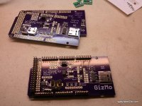
Cycle Analyst V3 preview and first beta release

justin_le said:
shorza said:
Justin, for some reason my 'amps drawn' displays up to 0.25a either side of zero when first starting the bike. It seems to drift over time (or maybe temperature).

By first starting the bike, you mean first applying throttle, or first powering it on?

What causes this and will it effect my amp hours reading?

There are a few things that can cause issues with the current offset
1) A controller with the CA-DP wiring done incorrectly where the white or blue sense wires aren't located right on the shunt itself, but are instead placed somewhere else on the circuitboard that is nominally equivalent but not exactly.
2) Any situation where you blue and white sense leads are joined to ground at any point other than right at the shunt resistor itself.
3) A shunt resistor made of constantan or other material with a thermoelectric effect in conjuction with copper. This makes temperature gradients across one side of the shunt and the other produce a tiny voltage with the CA would mistake for a small current.
4) Water on the actual CA circuitboard messing around with the signals
5) A bad/intermittent contact on one of the current sense leads (white or blue wire again)

How do you have your CA connected?
I mean when turning on the bike. My CA is the DP type, and controller is 18 FET from lyen. Maybe it's best that I open the controller and check the sense wires.

Thank you.
 
teklektik said:
Opus the Poet said:
Justin already told me how to set the cruise control to a lower speed by using a throttle on the Aux input so the rider will still get assist when the input power levels are met, just at a lower speed as conditions dictate.
So, saying this a different way, it seems that you want an ebike with a conventional speed throttle (i.e. throttle sets a desired speed) but that will only apply motor power if the rider pedals with at least some preset minimum effort. The assistance is not proportional - the motor will make up whatever the difference between the rider input and the throttle setting. It also has a 'cheat' mode that disables the mandatory pedaling requirement (so the rider can "ride along without putting any power into the pedals").

Correct?

Mostly. The customer did not specify a "cheat mode", only that assist would not be available without the minimum level of HP input. From what the customer is telling me the cheat mode would have to be very hard to get into if it existed. When I mentioned the need to calibrate the torque sensor with a force on the pedals at startup he was not happy with that because the customer could just recalibrate without pressing on the pedals and get assist just by turning the pedals over with no force applied.
 
shorza said:
I mean when turning on the bike. My CA is the DP type, and controller is 18 FET from lyen. Maybe it's best that I open the controller and check the sense wires.

Yes, that would be the next thing to do. The sense wires and ground should be soldered right at the shunt itself. If you have the CA ground soldered on the S+ side, then any current from accessories running of the CA's DC plug will also show up on the CA which is cool, but it means that your CA's ground potential will vary with the controller ground when there are large currents flowing. So for the CA V3 setups where the throttle interface is more important, I recommend having the CA's ground tied to the controller ground on the S- side of the shunt.

-Justin
 
Diamondback said:
this is pretty much exactly how i would want my set up. so i can pedal lightly (even at high cadence) and get zero assist from the motor.
but as soon as i start exerting torque on the cranks (say 100w-150W as i start climbing a hill for example) the motor would start to assist, up to a level that can be dialed in by the PAS knob...

if it's a fairly simple code change, i for one would vote for it...

OK, consider it done. A PAS assist offset setting in N-m has now been added to the Beta20 firmware. I've made it so that you can set it positive or negative, and that way it's possible to make the assist factor kick with a decent amount of power even if you are pedaling with almost no torque, for those who have the opposite desire.

-Justin
 
thanks heaps for the change.

this will really improve my set up. the way i like to ride, is actually pedal, and only use the motor for hill climbing.
with this new offset, i can pedal and have the motor not run, until i hit a set threshold.

perfect.

thanks again.

Jason.
 
Ready for testing...

2012-10-21 14.57.55.jpg

-methods
 
Some strange behavior - anyone else seeing this?

When I set the throttle control mode to "Current", current limit set to 99amps,
ThrI -> Cntrl Mode
{ [Pass-thru] | Current | Speed | Disabled }

the amps cutoff bounces back and forth between "A" and "a" on the "awsvt" diagnostics/debugging screen. This happens whether the bike is at rest or moving, zero or partial throttle, etc., and at pretty much any amp reading/output.

lollandster reported similar behavior in this post: http://endless-sphere.com/forums/viewtopic.php?f=4&t=37964&hilit=cycle+analyst+v3&start=660#p649873

It behaves this way while throttle is in [Current] control mode. When I set the CA to [Pass-thru] control mode, the "a" stops bouncing. I own two CAv3's with firmware B19 loaded - both behave exactly the same.
 
MattyCiii said:
It behaves this way while throttle is in [Current] control mode. When I set the CA to [Pass-thru] control mode, the "a" stops bouncing. I own two CAv3's with firmware B19 loaded - both behave exactly the same.

Hi Matty, this is exactly as it should be. With your throttle set as a current throttle mode, you are effectively dialing your current limit from 0A up to 99A (or whatever your AMax setting is). When your throttle throttle is off, you are setting the current limit right down to 0A, so any time the CA sees even a hair more than 0A it would set the current limit flag letting you know what's up. At part throttle, it is the same thing, if you are commanding say 10A, then as the current jitters above and below 10A you will see the limit flag flash accordingly.

-Justin
 
For some reason I had missed what awsvt actually was. Please confirm that I've got it right this time:
A- Current limit (Amps)
W- Power limit (Watts)
S - Speed limit (kpm/mph)
V - Voltage limit? LVC?
T - Temperature limit

Lower case = output not limited
Upper case = output limited.
 
lollandster said:
For some reason I had missed what awsvt actually was. Please confirm that I've got it right this time:
A- Current limit (Amps)
W- Power limit (Watts)
S - Speed limit (kpm/mph)
V - Voltage limit? LVC?
T - Temperature limit

Lower case = output not limited
Upper case = output limited.

Indeed, that's exactly right. There are a few fault/limit flags that aren't thrown, such as the minimum start speed limit, and the throttle overvoltage limit, but the 5 main ones are shown as described. -Justin
 
justin_le said:
MattyCiii said:
It behaves this way while throttle is in [Current] control mode. When I set the CA to [Pass-thru] control mode, the "a" stops bouncing. I own two CAv3's with firmware B19 loaded - both behave exactly the same.

Hi Matty, this is exactly as it should be...

Thanks Justin!
I'm sure glad "there's no such thing as a dumb question" because otherwise, mine sure would have been! :oops:
 
VRdublove said:
Has anyone here successfully run the V3 with a Castle HV160 ESC?
Yes, I do.

1) You have to set throttle output mode to RC Pulse.
2) I bought and use the "Shunt-RC" from here: http://www.ebikes.ca/store/store_rc.php.
3) You'll have to open the CA and solder the yellow wire in the 6-pin controller JST connector to the +5v on the throttle pad shown here: http://www.ebikes.ca/store/store_CAV3.php

I had a PM conversation with RatKing who really helped me out. Forgive the loss of formatting, the whole conversation is posted here:
Re: Cycle Analyst V3 preview and first beta release
Sent: Tue Jul 31, 2012 2:26 pm
by MattyCiii

Thanks for the response!
It's been bugging me all day. I'm at work so have no time/test equipment, and won't be able to check till tomorrow night. You're right - I need to go back to the setup that worked, then move forward from there. If I get things working I think I'll get the multimeter out and test all the DC voltaves (e.g., with the "+5" source) with the 6s battery, then see if anything changes with the 8s.

It's just disappointing to have had it all going, then with few changes to have nothing at all. I guess I have to set my mind to the fact that I need to slow down, dive into the documents, and prepare to do some methodical troubleshooting - test all connections, etc.

Thanks again,
Matt
Re: Cycle Analyst V3 preview and first beta release
Sent: Tue Jul 31, 2012 1:58 pm
by Ratking

Hello

I have re done all of my wires, so I don't remember the color code anymore. From where to where does the yellow wire go?
I don't see how it could work on the bench but then suddenly not work on the bike?
Have you checked all the necessary software on the ca?

You should have one wire from ThO(throttle out) to the signal wire of the hv160.
You also need ground and +5v.

Just control that you have that set up right, and check the mapping on the throttle in and out on the ca. Remember that the hv160 need under a certain pulse train on the input for start up. If the throttle is too high it wont let you start.

Please give me more details, because its hard to figure out if its hardware or software.
You could start with the 6s battery and see if it works then. If it does, I would see if everything was set up right in the software.
Re: Cycle Analyst V3 preview and first beta release
Sent: Tue Jul 31, 2012 12:49 pm
by MattyCiii

Thaks for the reply. I went out of time awhile and could not modify the bike. I'm back, bench tested the CA - worked fine, went for the real world test - fail. Details here: viewtopic.php?f=4&t=37964&hilit=throttle+pad&start=510#p617339

I wonder if I set things up the same way you did.
To confirm - you soldered the yellow wire to the +5v on the "dedicated throttle input" secion shown in the first post of this thread, yes?

Please let me know, THANKS,
Matt
Re: Cycle Analyst V3 preview and first beta release
Sent: Tue Jun 26, 2012 10:13 am
by MattyCiii

Thank you!!
This is my first build and my grasp of these things is shakey. But what you said all makes sense, and I agree - it's probably the best way to do things since I'll be routing the signal wire from the CA to the controller anyway, why not have the CA provide + and -

I'm using an Astro 3210, it worked rock solid with a cheap $11 servo tester from ebay/Hong Kong, so hopefully no twitchy with the CA. I'm re-reading the entire CA V3 beta now, it is so much easier to understand something you have in hand than trying to picture it in your mind.

Thanks for the info, I really appreciate it!
~Matt
Re: Cycle Analyst V3 preview and first beta release
Sent: Tue Jun 26, 2012 8:26 am
by Ratking

Hello

First of, I don't know if there is a better way of doing this, but as I tried you will need; ground, +5v and signal for the controller to work. Some people will say that you only need ground and signal, I tried it, but no cigar.

Since the ca have common ground, you can use the black wire, pin 2 as ground for the controller, Green, pin 6 is used as throttle signal, and I used the yellow wire as +5v. I had to re solder the yellow wire to the ca board. I used the throttle input +5v one. It should deliver enough current for our need. I use two controllers and have not had any problems.
I don't know what kind of motor you will use, but I would suggest to set the throttle ramp up time to 250-300. Default is 500 and it was very nervous and twitchy.

If there are problems, just ask. I don't mind helping if I can.


Henning
Re: Cycle Analyst V3 preview and first beta release
Sent: Mon Jun 25, 2012 9:45 pm
by MattyCiii

Subject: Cycle Analyst V3 preview and first beta release

Ratking wrote:
Thanks to Justin, I got my setup working last night.
I'm using the new ca with a hv160 and a Turnigy 80-10 130kv. I have not tried it on the road yet, still waiting for the final parts, but I can tell that the ca will be mandatory in every build I make.
Both the current and speed control worked flawless at the bench, only complain will be a short throttle range. In speed mode, the motor rpm will be max long before full throttle is applied.
I have the pulses set to min 0.99 ms and max 2.00 ms. Tried different variations, but with no luck. I want to try it with a heavy load before I make any assumptions, I will soon find out.


Hello I recently received my V3 CA preview, and HV160. I have the HV-160 operating off a servo tester just fine. Can you tell me which CA wires connect to the 160? I'm guessing pins 3, 4 and 6 of the JST-6-M (from here viewtopic.php?f=4&t=37964&start=420#p601462), but I don't know which goes to what color. What works for you?
Thank you,
Matt

In the end its not a lot of work, but required a bunch of thinking for me.
 
Justin
Using V19
I have finally hooked up the pas through throttle.
I like the fact that you can set the input and output levels to get the throttle to start the motor as you turn the throttle.

I did find that the throttle is slow to respond compared to the direct throttle, I adjusted the ramp up, but it stayed slow. I also noticed that it ramped down slow, I have yet to adjust this.

I do like to wheelie my bike, with the slow ramp it is much harder to get the wheel to lift. The ramp down I nearly went over backwards as it did not shut off immediately. :eek:

I think that part of the problem is that the CA is winding back the throttle in anticipation of the power limit, to prevent over shooting the setting.
In direct mode I had the power limit set at 1800w if you turn the throttle you get full controller power for a second (about 2500w) and then it ramps back to 1800w.
In pass through mode it is already limiting the throttle at 1600w in anticipation of the 1800w limit. I increased the power limit to 2500w as a test, but it still felt sluggish.

I did like the delayed power limit in the direct mode, it gave you the ability to turn the throttle and get a power boost to out of the way of danger, without having to have the current limiting set high enough to burn out the motor. In direct mode I got about 1 second of full power.

:idea: It would be good if you could do this in the pass through throttle mode, Just have an adjustable delay. It is like turbo lag in reverse.
 
cruzxia said:
Justin
Using V19
I have finally hooked up the pas through throttle.
I like the fact that you can set the input and output levels to get the throttle to start the motor as you turn the throttle.

I did find that the throttle is slow to respond compared to the direct throttle, I adjusted the ramp up, but it stayed slow. I also noticed that it ramped down slow, I have yet to adjust this.

Hey Cruzxia, if you have your throttle ramps both set to 999 but you still see a less than instant up and down ramp on the actual output, then it could again be related to some of the other feedback gains (ie. AGain, WGain, and IntSGain) that are limiting the output change, and finding which value is causing the delay on the output and increasing it will help. This won't be necessary in the Beta20 code, but let me know with this one if that makes a difference.
 
I have been testing different values for the gains.
I have now set the throttle ramps both to 999
The AGain To 50 and the WGain to 5
It has improved the response of the throttle and the bike. Watching the throttle in the display screen, the output still only goes to about 2.5v under hard acceleration, so the controller only gives about 60% power. I think in direct throttle mode it gets the full 4.2v and then ramps back down to 2.5v as the CA limit kicks in.

Note: I did put a 1K resistor on the green CA control line in anticipation of connecting the pas through throttle. As I was using it in direct mode, it would have dampened the affect of the CA when it was trying to limit the power. It defiantly still limited the power, but perhaps not as abruptly as it would without the resistor.

Is it possible to alter the firmware so that you don’t need the diode in direct connection mode? You could set the port as an input when not limiting the throttle. That way you would not need the diode and you could monitor the throttle voltage via the input. It would then be easy for me to compare the two setups, as I can just swap plugs on the throttle line. At present I have to move the green wire from TH0 to THd

I think that the motor actually ran cooler because it accelerated faster, the power was on for a shorter amount of time. Eg going from 20 – 30 kph with an inrush or say 2400w before ramping down to 1800 it takes about 2 seconds, and then power down to 400w to maintain speed.
In past through mode it limits at 1800w so the acceleration is slower, taking 4 seconds to achieve the same speed change.
Adding up the power 4200w vs 7200w for the same speed change = warmer motor.


Speed Limit Test
I have also tested the speed limiting. With the stock CA settings it was surging violently. I think it is due to the high torque motor in a light bike. This bike dose accelerate fast.
I revised the IntSGain down to 40 and the DSGain down to 50 and it smoothed out the surging. I did note that it takes a while for the speed limit to kick in. E.g I set it at 19kph for the test, when I accelerate it over shoots to 36kph and then shuts off the throttle until it drops to about 16kph, then it speeds up and settles around 18.9kph.
 
Hi everyone, i have a question about throttle settings. I connected my new v3 ca today and when i pulled the throttle my wheel spun very slowly, i have a std chinese hall sensor throttle can anybody specify what the throttle settings should be.
Thanks, Brettster
 
Hi Brettster,

Start reading the thread. Telektek did a very very nice writeup here how to connect everything and what everything does. Also, with the very limited information that you provide, it can be pretty much anything from battery problems to wrong rdshunt. This CA is so advanced, you better start reading now.
 
Again, start reading the thread. Teklektik even posted the link directly to what you now are asking for.
 
Hi everyone, I am running windows vista, when I plugged in the cable that came with the CA, windows said drivers failed to install, anyone know where I can get some software drivers to enable the com ports on the garage computer.

Any help would be much appreciated.


Cheers,

Brett.
 
Brettster said:
I am running windows vista, ... anyone know where I can get some software drivers to enable the com ports on the garage computer.
Justin provides firmware update instructions as well as a link to the programming cable manufacturer on the Grin Tech V3 page. The cable and the USB-TTL converter chips it uses are manufactured by FTDI. Please see the FTDI download site for VCP (Virtual COM Port) drivers for various OSes.

The FTDI OS Support page calls out Windows Vista as a supported OS. It also mentions an FTDI document, AN_107 Advanced Driver Options, however, for this application the FTDI Windows drivers will work as installed without any manual or advanced configuration.
 
I cannot not find that in that thread.
It is about speedometer.
As we know CA can measure speed.
But I see a problem with CA when it comes to odometer function.

"TotKm" or "TotMi" if you are in USA are registered in Lifecycle Statistic screen #7.
The problem is that you cannot enter any number of kilometers/miles into "totkm" or "totmi" ,
km and miles are counted ONLY from zero when CA is installed.
Even in tiny, cheap cycle computers you can enter any number of miles into odometer,
you can enter actual millage of your ebike at the time of installation of new cycle computer.
When I buy CA for used ebike , already with millage you would like to enter actual millage into CA.
I do not find it possible with CA.
It is kind of lacking to be able to see speed but not actual millage of vehicle.
Of course on gasoline car you don't change odometer reading but CA is totally different, it is add-on to existing ebike.
 
miro13car said:
I cannot not find that in that thread.
It is about speedometer.
As we know CA can measure speed.
But I see a problem with CA when it comes to odometer function.

The problem is that you cannot enter any number of kilometers/miles into "totkm" or "totmi" ,
km and miles are counted ONLY from zero when CA is installed.
The odometer preset is a setup parameter available since the initial V3B12 release. Please review explanations of all Setup parameters in the most recent firmware on the Grin Tech V3 web page:
Setup Menu Details for Beta19 Firmware
2. Setup Spdometer
d. TotDist: Lets you pre-load the odometer.
 
Back
Top