Another Lebowski controller

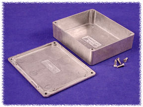
I've gone for the same style of sealed box as you, Lebowski, but in a smaller size. I've opted to squeeze things into a Hammond 1550M sealed diecast box, that's 120mm x 100mm x 31mm, so not that much larger than a Xiechang 6 FET controller. This is the box (minus the rubber gasket:
1550M_Is.jpg


and here are some images of the boards, first the main board that fits to the bottom of the case, with the FETs fitted on the underside:

Main board component layout.JPG

The sensor board sits on top and carries the Hall current sensors and the phase voltage dividers:

View attachment 2

They stack on top of each other, with the support pillars connecting the phase outputs. This leaves a clear space at the bottom right corner for the cables and cable gland to the outside world:

Both boards component layout.JPG

Finally, this is how the stacked boards look viewed from the right side in the box, *just* enough clearance to get everything in:

Profile view.JPG

I just need to double check that the layout is error free, then I should be ready to make another set of boards.
 
nieles said:
do the status leds have a current limiting resistor in series with them?

Limiting resistors are not needed as I've opted to use 5V LEDs that have built in limiting resistors. Saves a bit of precious board space!
 
Another step forward, I found time to make the boards today:

Main board.JPG
This is the main board that holds the dSPIC, the FETs and drivers


Sensor board.JPG
This smaller board sits on top and holds the current sensors and the phase voltage interface components.


I've changed the case to a small sealed diecast box:

Case.JPG
The boards are a snug fit in this case, but there is room at the lower right corner for the cables:


Case and boards.JPG
I've also machined up some copper stand off supports that will be soldered to the lower board phase connections and screw to the sensor board, so they can perform the dual function of mounting the board securely and taking the high current phase connections up to the sensor board.

I may get some more done tomorrow, but I'm scheduled for surgery on Saturday, so will probably not get much more done for a little while.
 
Jeremy Harris said:
I'll just make the board myself, as I've done with a few other projects documented on here, using the laser toner transfer method. Single sided is a heck of a lot easier for DIY, I've found, as getting good registration with the toner transfer method is tricky.
.


Sparkfun is running a service called BatchPCB. https://www.batchpcb.com/faq It is as cheap as cutting the board yourself, and you can get 2 layer boards with plated-through holes! $2.50/sq in plus $10 setup fee. The trick is, they put a few dozen custom orders together and have them all run at once, which makes them pretty cheap. I just spent $50 getting set up to do photopositive etch myself, only to find out about these guys after I recieved all the chemicals. :?
 
llile said:
Sparkfun is running a service called BatchPCB. https://www.batchpcb.com/faq It is as cheap as cutting the board yourself, and you can get 2 layer boards with plated-through holes! $2.50/sq in plus $10 setup fee. The trick is, they put a few dozen custom orders together and have them all run at once, which makes them pretty cheap. I just spent $50 getting set up to do photopositive etch myself, only to find out about these guys after I recieved all the chemicals. :?

Yes, I've seen their service, but they are relatively expensive (because of the high shipping cost) and it takes a long time (it's only relatively cheap if you happen to live in the USA). There are services here that can make boards for a reasonable price, but again it takes time, and if you've made a board error (as happens from time to time) you end up with another delay and more cost. Those boards above took me a couple of hours or so to make, with most of the time spent cutting out the boards and the sensor slots.
 
Just something to look at... When building the big Lebowski controller I went through about
20 NCP5181's, the high side driver blew up one after the other. I checked everything and
finally narrowed it down to one specific specification of the NCP5181. For the high side
driver the pin connected to the source of the high side FET (the 'ground' of the driver IC's
high side output stage as it were) is not allowed to go below -1V. But with the parasitic
inductances that one has this is difficult to guarantee.
At this point I'd blown all my NCP5181's so I ordered a bunch of IRS2186 gate drivers. These
can handle this particular node going down to -5V. The 2186's have survived where the 5181's
blew up, so... no more 5181's for me. Plus the 2186 are 4A !
 
Thanks, that's worth knowing. Good job the IRS2186 chips look to be pin compatible with the NCP5181's and also a good job that I fitted sockets to my board for the gate drivers!

I should get the boards finished tonight or tomorrow, so will post an update. The stacked board system seems to have worked quite well, but was a lot of work to fit into the small box I'd selected.
 
just slightly off topic. but a question...

with 4A of drive could the IRS2186 be used to drive a pair of HEXFETs directly with some minor adjustments to the snubber circuits and individual gate resistors of say 20R?

Jeremy, really good looking board and box. looking forward to reading your progress.

rick
 
Sorry, missed that question, Rick. From a quick read of the data sheet it looks like the drive capability of the 2186 is pretty much up to driving some pretty big FETs directly, probably even the massive VMM 650 HiperFETs I have for the big controller I'm planning.

Here's what the populated boards look like.
Lower board.JPG

The lower board has three copper posts that take the phase outputs up to the current sensors on the upper board. The FETs are under the board, you can just see the top of them poking out. The commutation capacitors are directly on top of each FET pair, a 680 µF Rubycon ZL plus a 1 µF low ESR polyester cap for each pair.

Both boards assembled.JPG

The upper board plugs into a 10 way header on it's lower edge and is secured with screws to the three copper phase pillars. The underside of the board where the phase pillars sit has been beefed up with copper sheet soldered to the tracks.

The power supplies (both switched mode, to the right of the board) have been tested and are OK. The small red jumper on the right is the FET drive power disconnect for testing, the tactile button is the "setup and store" button. The LEDs are all 5V ones, so no need for more bulky resistors on the board. The three pin and five pin headers to the right of, and above, the button are the throttle and Hall sensor connections. The three pin header over at the extreme lower left on the lower board is the serial port for programming.

The controller is bolted to an alloy plate, rather than fitted to the case, just to make it easier for testing. All I need to do now is knock up a serial interface (hopefully the FTDI board I have should work OK, with some adaptation) and then start testing.

This is only a low power controller, designed for 60V max at around 20 to 30A. If I can get this working OK then it'll form the test bed for the much bigger controller I have planned.
 
cool :D I'm very curious how your output stage will do, whether the caps
on the output stage are enough or whether you'll need snubbers. With the RS232,
make sure you have the polarity correct, it should not give you any problems
when correctly setup.
 
Jeremy what are you planing to use the big controller for? And you have 3 of the big mosfets? I think I have one left thats ok lol.
My only problem is the VMM-650 mosfets are discontinued.... If you blow one what do you do?
 
Arlo1 said:
Jeremy what are you planing to use the big controller for? And you have 3 of the big mosfets? I think I have one left thats ok lol.
My only problem is the VMM-650 mosfets are discontinued.... If you blow one what do you do?

The plan is to build a controller to run a paralleled pair of Colossus 80-100 motors (on a common shaft). The reason for choosing this arrangement is really because I can then fit this double motor in the space where the air box used to be on my RD50, leaving most of the old engine/gearbox space for the battery pack. I'm hopeful that I should be able to get around 10kW from this arrangement, which is probably enough for what is a pretty light bike.

I have some spare VMM650s just in case, but for the sort of power level I'm aiming for (72V at around 150A) I'm hoping that they should be pretty robust. My only real worry is that the switching losses may be a bit high, as they aren't the fastest FETs around. If push comes to shove then I may have to look at using banks of IRFP4468s, or maybe even two linked controllers with 4468's, one for each motor. This latter approach may be easier to do with torque demand controllers, because it should be fairly easy to get both motors to share power evenly.
 
Here is a screen shot of the new powerstage Im working on. This is set up to handle 3 TO247 fets (irfb4468-irfb4668) per hi and low side for a 18fet controller in total that I think I will stack to make compact. I Also think I can make TO264 fets work with a twist which meens the heat sink bar will need angles machined in it. I also left a Gate out and return on each side to run my Big powerstage for now. These have a spot for snubbers if needed and they have a place for on board 400amp current sensor so I should be able to run ~350phase amps. As soon as my first set or TO220 boards come in and they work I will order a set or two of these.
 
Back
Top